Production Test
This topic describes test modes available for Wi-Fi modules. You can send one or more test commands to the modules and evaluate the returned data to determine if the Wi-Fi functionality works as expected.
Overview
The test commands are only used for production scenarios to help you determine the functionality and communication capability of the Wi-Fi module.
-
Scan the specified router
The module scans the specified router’s SSID on receiving
0x0efrom the MCU and returns the signal strength. The MCU determines whether the Wi-Fi RF performance is acceptable based on the signal strength. This mode does not require an internet connection and provides good efficiency. You can test multiple devices at a time. -
Connect to the specified router
The MCU sends the SSID and password of the specified router to the module through
0x2c. The module connects to the router and returns the status of cloud connectivity so that the MCU can determine the test result based on what the module returns. This mode requires an internet connection. The network capacity determines you can test limited devices at a time. The test item of cloud connectivity makes the result more reliable.TYWE3SE modules do not support the test mode of connecting to the specified router.
Scan the specified router
You can define the trigger of the test. After the initialization is completed, the MCU can send 0x0e to the module. The module will scan the specified SSID tuya_mdev_test and return the signal strength. The MCU determines whether the Wi-Fi RF performance is acceptable based on the signal strength.
Things to note
- The router does not need to be connected to the internet and only broadcasts a Wi-Fi signal named
tuya_mdev_test. It is recommended that the distance between the router and the device under test should be about five meters. - Generally, if the signal strength is greater than or equal to 60%, the device is acceptable. The specific testing conditions depend on your production line and environment.
- The MCU should send the test command to the module after the initialization is completed (that is, the MCU has responded to the heartbeat and product query packet). It is recommended that the test should be triggered five seconds after power-on.
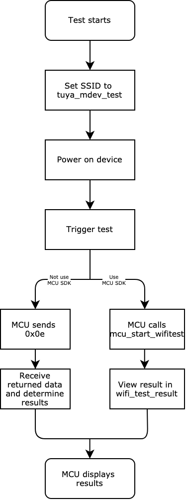
Test process
-
A 2.4 GHz wireless router (internet connection is not required). Set the router’s SSID as
tuya_mdev_test. -
Power on the device under test. Trigger the test after the initialization is completed. You can define the trigger as needed. Setting the less frequently used key combination is recommended.
-
Send the correct test command to the module according to your development solution. The test command depends on whether you use the MCU SDK or not.
-
MCU SDK is used
The MCU callsmcu_start_wifitest()to enable the test when it detects the test trigger. -
MCU SDK is not used
Send0x0eto the module to enable the test. For more information, see Wi-Fi functional test (scan the designated router).
For example,
0x55 aa 03 0e 00 00(checksum)Field Bytes Description Header 2 0x55aa Version 1 0x03 Command 1 0x0e Data length 2 0x0000 Data Data None Checksum 1 Start from the header, add up all the bytes, and then divide the sum by 256 to get the remainder. -
-
View the returned data.
The method of viewing results depends on whether you use the MCU SDK or not.
-
MCU SDK is used
View the test result from
wifi_test_resultinprotocol.c.
void wifi_test_result(unsigned char result,unsigned char rssi) { #error "Complete the code for test results and then delete this line." if(result == 0) { // Test failed. if(rssi == 0x00) { // The router with an SSID of `tuya_mdev_test` is not scanned. } else if(rssi == 0x01) { // The module is not authorized. } } else { // Test succeeded. // RSSI indicates the signal strength, ranging from 0 to 100. 0 represents the weakest, and 100 represents the strongest. } }-
MCU SDK is not used
Determine the signal strength based on the returned data. For more information, see Wi-Fi functional test (scan the designated router).
For example, if the module returns
0x55 aa 00 0e 00 02 01 64, it indicates the signal strength is 100.The MCU sends the following command.
Field Bytes Description Header 2 0x55aa Version 1 0x03 Command 1 0x0e Data length 2 0x0000 Data Data None Checksum 1 Start from the header, add up all the bytes, and then divide the sum by 256 to get the remainder. The module returns the following command.
Field Bytes Description Header 2 0x55aa Version 1 0x00 Command 1 0x0e Data length 2 0x0002 Data 2 - Data[0]:
0x01means success. Data[1] indicates the signal strength, ranging from 0 to 100. 0 represents the weakest, and 100 represents the strongest.0x00means failure.
If Data[1] is0x00, the specified SSID is not scanned.
- If Data[1] is
0x01, the license for authorization is not flashed to the module.Checksum 1 Start from the header, add up all the bytes, and then divide the sum by 256 to get the remainder. - Data[0]:
-
-
Display test results. You can feed the test results to speakers, displays, or LED indicators for indication.
Is this page helpful?
YesFeedbackIs this page helpful?
YesFeedback


