Quick Start
This topic will walk you through trying out firmware development for a smart Zigbee product by editing the Zigbee switch demo.
With the demo, you can implement control of the LED (D2) via the physical button (S2) on the ZSU microcontroller board or the mobile app. Pressing and holding the button (S2) will reset the device to enter pairing mode. Pressing this button will turn on/off the LED (D2).
Prerequisite
Hardware
-
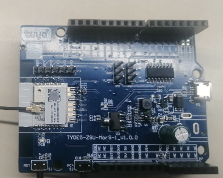
A ZSU microcontroller board. Alternatively, choose a Tuya’s Zigbee module or a microcontroller board of a different model.
-
J-Link debugger
-
USB to TTL converter
The following describes the pins used in the demo. For more information about pin definitions, see ZSU Datasheet.
Silkscreen marking Pin Description S2 PC4 The button pin. It is initialized to high level and active low. D2 PC5 The power status and network status LED. It is active low.
Software
Tuya Wind IDE can run on four types of development environments. You should configure the environment according to your system.
- Windows 10
- Linux (Ubuntu 18.04 and Ubuntu 20.04)
- Linux virtual machine (VirtualBox and VMware) on Windows
- Windows Subsystem for Linux (WSL) on Windows
Applications based on the Zigbee SDK should be built on a Windows environment, so this topic only describes the environment setup for Windows. Before you start, get the following ready.
-
Code editor
Install Tuya Wind IDE and IAR Embedded Workbench for Arm on your Windows PC. For more information, see Environment Setup.
-
Tuya Developer Platform
Before getting started, create a product on the Tuya Developer Platform to get a product ID (PID). For more information, see Create Products.
-
Zigbee SDK and application demo
The following section will describe how to get the Zigbee SDK and demo.
-
Flashing tool
-
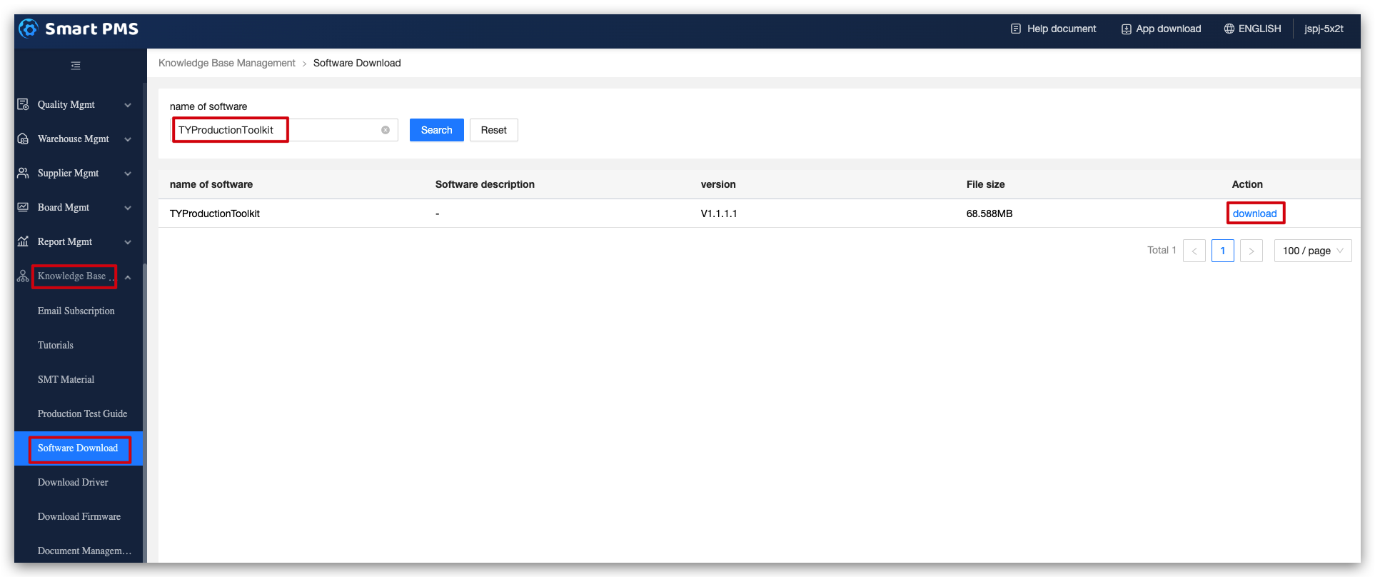
Open the Smart PMS. If you do not have an account, create one.
-
Choose Knowledge Base Management > Software Download. Search for TYProductionToolkit and click download.
-
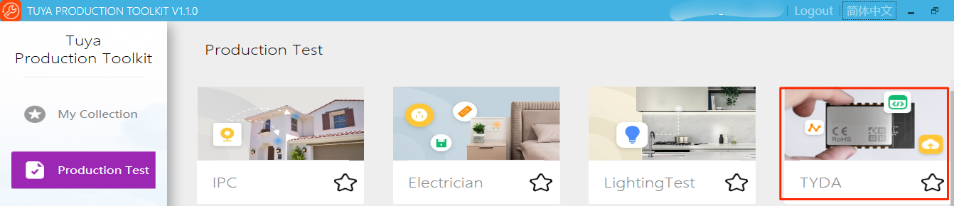
After installation, open the software. Choose Production Test and TYDA. The flashing tool will open.
-
Get the SDK
Create a Zigbee product on the Tuya Developer Platform and download the SDK.
How to: Install Visual Studio (VS) Code and then install the Tuya Wind IDE extension. The SDK can be downloaded from the IDE.
This is the official channel to get the SDK, which is maintained by Tuya. The SDK you download from the unofficial channels is not guaranteed by Tuya.
This section describes how to download the SDK from Tuya Wind IDE.
-
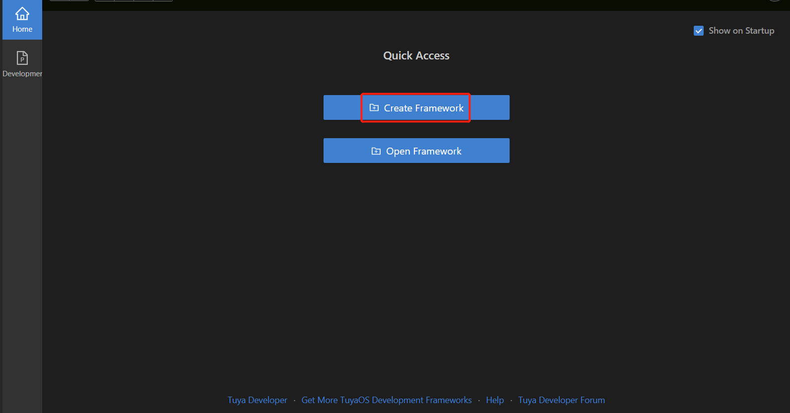
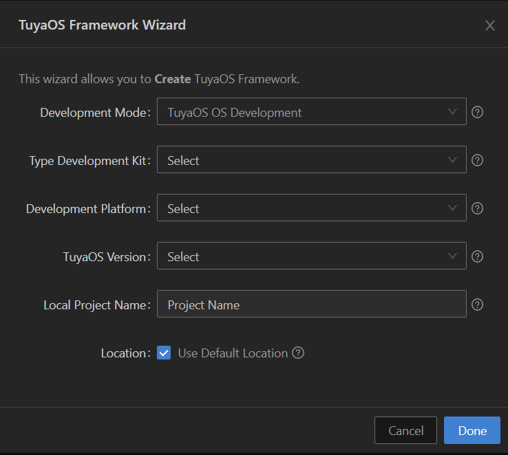
Log in to Tuya Wind IDE with the account of Tuya Developer Platform. Click Create Framework.
-
In the TuyaOS Framework Wizard, complete the required information based on the configuration of your product created on the Tuya Developer Platform. Then, click Done to download the SDK. This might take a while.
After the framework is created, you will find all the files in the left pane.
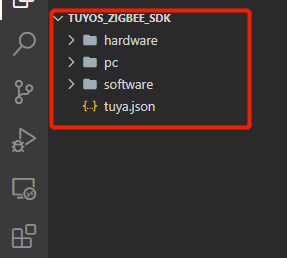
Open software > TuyaOS folder that contains routines and developer documentation.
The following describes the directory structure.
TuyaOS
  ├── apps        // Sample applications. You can create a project in this folder and then write code.
       └── tuyaos_demo_zg_light2    // A demo of Zigbee cool and warm white light.
├── components// Open-source components. You can create a folder to store your components.
├── docs        // Developer documentation.
├── include     // APIs for TuyaOS development frameworks.
│    ├── adapter  // APIs for adapters.
│    │   ├── adc
│    │   ├── bluetooth
│    │   ├── display
│    │   ├── flash
│    │   ├── gpio
│    │   ├── hci
│    │   ├── i2c
│    │   ├── init
│    │   ├── network
│    │   ├── pwm
│    │   ├── rtc
│    │   ├── spi
│    │   ├── system
│    │   ├── timer
│    │   ├── uart
│    │   ├── watchdog
│    │   └── zigbee
│    ├── base
│    └── components
│        ├── tal_driver
│        ├── tal_syste
│        ├── tal_system_service
│        └── tal_zigbee
├── libs             // Dependent libraries for TuyaOS development frameworks.
└── tools            // Tools and scripts used to build projects.
│    ├── bootloader
│    ├── commander
│    ├── ld
│    ├── scripts
│    └── templates
└── build_app.bat    // The build script.
Get the demo
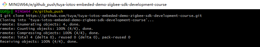
Open Git and run the following command to clone the repository. For more information about Git installation, see Environment Setup.
git clone https://github.com/tuya/tuya-iotos-embeded-demo-zigbee-sdk-development-course.git
Press Enter and wait for the clone to complete.
Edit code
Copy and paste the folder tuyaos_demo_zigbee_switch to /apps. Open VS Code and edit the sample code. The routine is based on the chip platform EFR32MG21A020F1024.
Modify the PID
Open the file appconfig.json in /apps/tuyaos_demo_zigbee_switch. Find firmwareInfo and replace the information with your Zigbee product information.
| Name | Description |
|---|---|
| module_name | The name of the module you use. |
| chip_id | The chip platform of the module you use. |
| image_type | The image type that identifies the type of firmware updates to determine whether to install an OTA update. |
| manufacture_id | The manufacturer ID that identifies the manufacturer to determine whether to install an OTA update. |
| model_id | The model ID that identifies device type. |
| pid | The product ID (PID), used to identify product type and app panel. |
| manufacture_name | The capability value of a product. |
-
module_namerepresents the name of the module. Make sure to specify it with the name of the module you use. Otherwise, authorization will fail. -
model_idrepresents the model ID of a Zigbee device, which is used to identify the Zigbee device type by the gateway. It varies depending on product types. Find the correctmodel_idfrom Zigbee Connectivity Specifications and specify it in theappconfig.json. -
pidis a unique identifier assigned to each product created on the Tuya Developer Platform. It is associated with product configuration and must be correctly specified in thefirmwareInfo.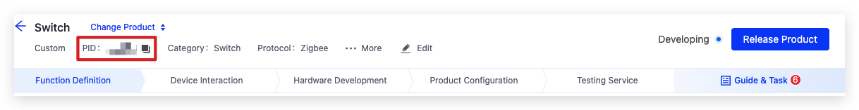
In the demo, replace
pidwith your own value. The modifiedfirmwareInfois shown below.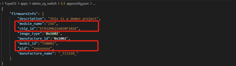
After you modify
firmwareInfo, a file namedapp_config.hwill be created automatically in theincludedirectory. Do not modify this file.
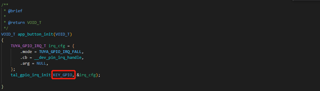
Modify the pin for reset button
Specify the pin for the reset button with the function app_button_init in app_common.c. You can also use the default pin.
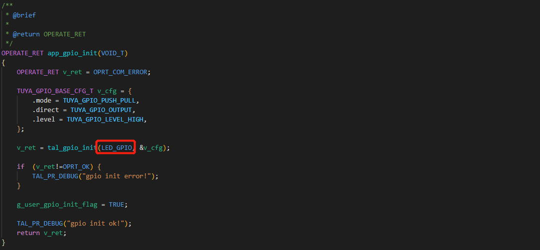
Modify the pin for LED
Specify the pin for LED control with the function app_gpio_init in app_common.c. You can also use the default pin.
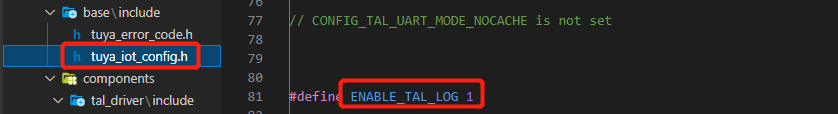
Enable device logging
Device logs can help you debug your code. The logging feature is disabled by default. In the SDK, set the value of ENABLE_TAL_LOG in tuya_iot_config.h to 1 to enable logging. Then, you can check logs using the USB to TTL converter and Debugging Assistant software.
Build project
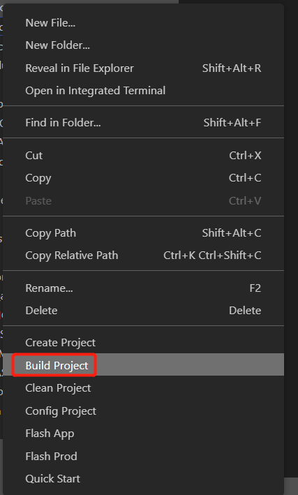
-
Open VS Code. Right-click the application project and choose Build Project.
You can click Quick Start to check out developer documentation.
-
After you choose Build Project, enter a version number in the format
x.x.x(such as 1.0.0) and then press Enter. -
The terminal starts downloading the toolchain and automatically builds your project after download. You can monitor the build result and output with the log. In the end, a folder
outputwill be created to store the generated files.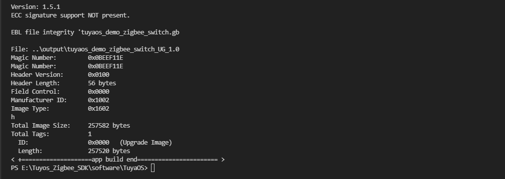
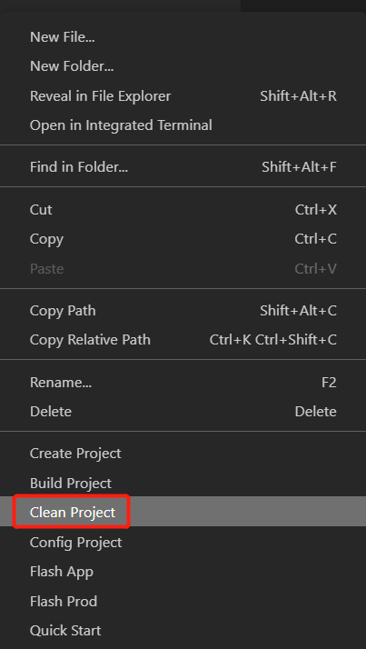
-
(Optional) To clear the build, right-click on the application name and choose Clean Project. Enter the version number and then press Enter.
Things to note
-
You must use Tuya Wind IDE to build a project for the first time. The built-in script will automatically create a build environment. After the project is built, you can find an IAR project in the
_buildfolder and then use a third-party IDE to debug your code. Note that a third-party IDE cannot generate files in theoutputfolder. -
The script will traverse the
demo,TuyaOS, andcomponentsfolders and add all the source files and header files to the target build environment. -
Tuya Wind IDE generates a build environment each time it is going to build a project. Take care of the following things:
- When you use Tuya Wind IDE to build a project, quit third-party IDEs like IAR and Keil to avoid project files being used by another program.
- When you use IAR or Keil to debug your code, do not manually add source files or header files to the project.
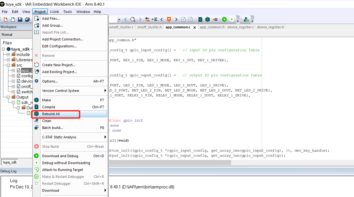
After the first time you build a project with Tuya Wind IDE, you can turn to a third-party IDE like IAR or Keil to debug code. Go to apps\tuyaos_demo_zigbee_switch\_build and double-click the .eww file to open the project. In the IDE, choose Project > Rebuild All.
Do not open your project by Open Workspace in IAR. Otherwise, the build process might fail. It is recommended to choose Clean before Rebuild All.
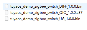
The generated files are stored in the folder output. The three binary files with the suffix QIO, UG, and DIFF are used for production, full updates, and incremental updates respectively.
Upload firmware
Upload the output files to the Tuya Developer Platform.
-
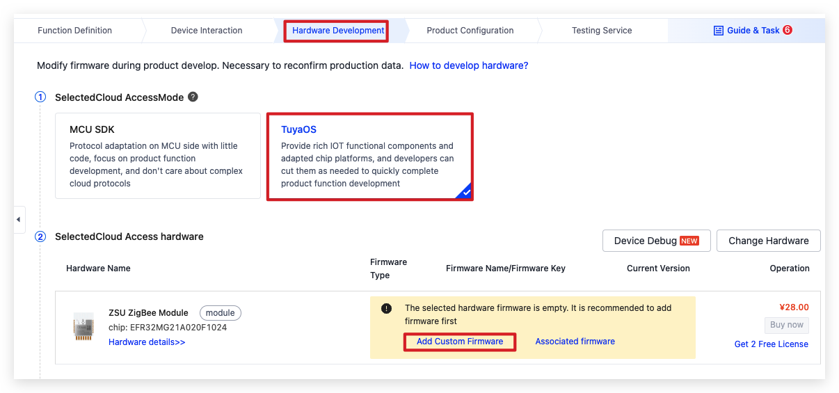
In the third step of Hardware Development, choose TuyaOS and click Add Custom Firmware.
-
Complete the required firmware information and click Generate Firmware Key.
-
Click New Firmware Version.
-
Complete the required information. Upload the QIO binary file for both the Production Firmware and User Area Firmware, because these two types of firmware mean the same thing for Zigbee protocol.
Get production credentials
-
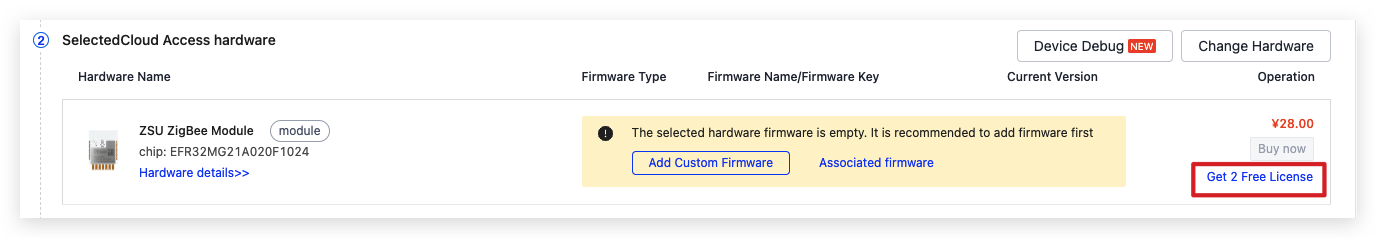
Click Get 2 Free Licenses.
-
Choose Credential for Delivery Mode and click Confirm.
-
Extract the downloaded file and open the
Token_information.txt fileto get the credential.
Flash firmware and authorize module
Connect the Sandwich development board to the programmer and computer. Follow the pin connection shown in the following table.
| J-Link debugger | Module |
|---|---|
VCC |
VCC |
GND |
GND |
SWCLK |
SCK |
SWDIO |
SDO |
RESET |
RST |
| USB to TTL converter | Module |
|---|---|
3.3V |
3V3 |
GND |
GND |
RXD |
RXD |
TXD |
TXD |
-
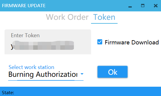
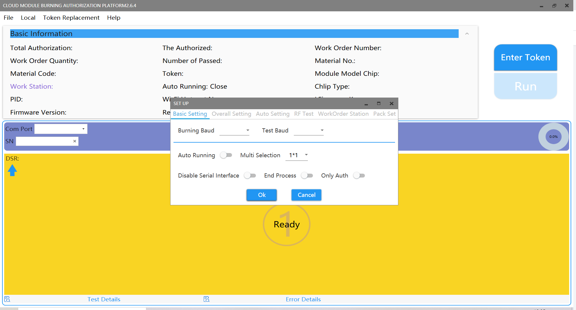
Open the Cloud Module Burning Authorization Platform software. Click Enter Token, enter your credential, select Burning Authorization for the work station, and click OK.
-
Choose the port connected to the J-Link debugger for the COM Port, 13 for the RF channel, and 115200 for both the Burning Baud and Test Baud. Click Run to start flashing and authorization.
-
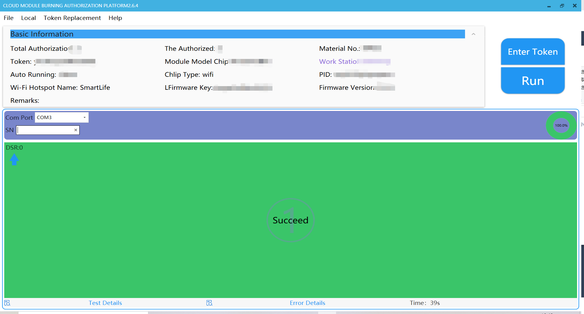
If the operation is successful, your screen will look like this.
Pair devices
After the firmware is flashed to the module, you can use the SmartLife app to connect the module to the cloud for remote control. You can download the SmartLife app for iOS or Android from app stores or scan the following QR code and download it.
-
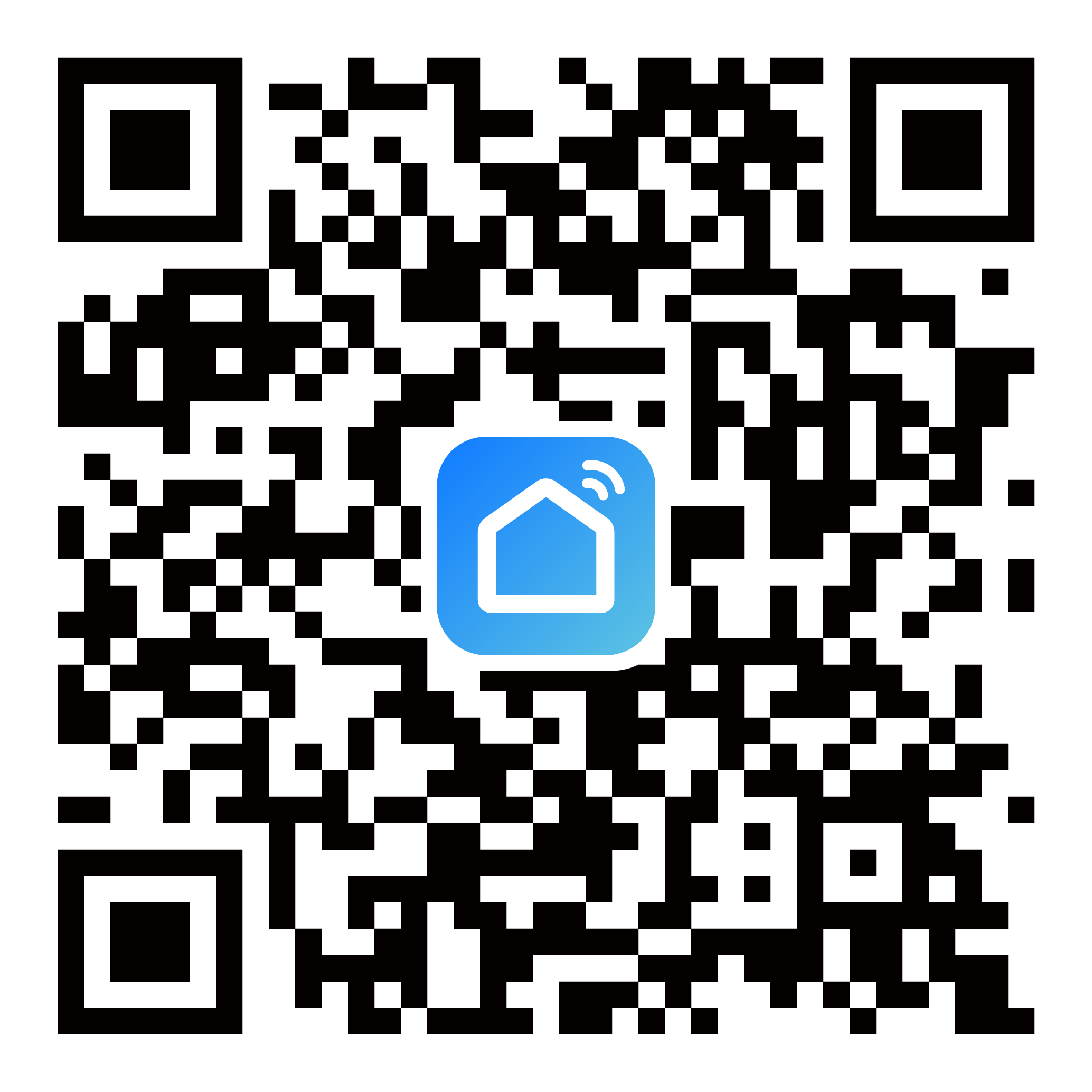
If your business is targeted at global markets, you can use this QR code to download the app:
Download the QR code of the SmartLife app
-
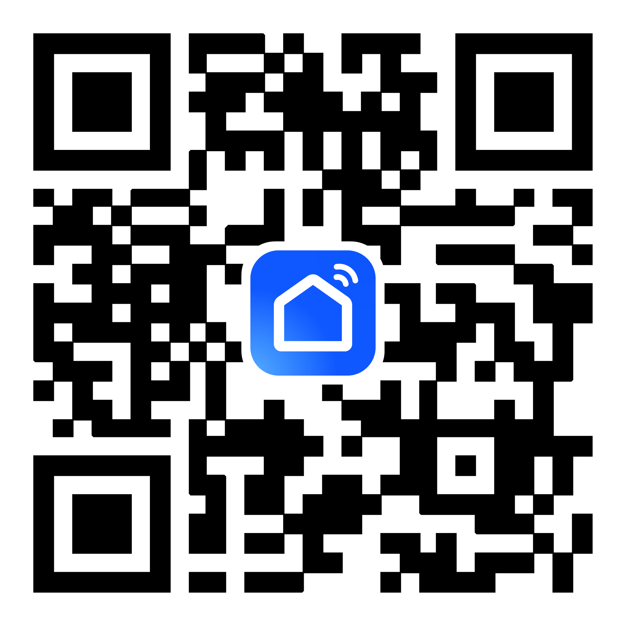
If your business is targeted at markets in mainland China, you can use this QR code to download the app:
Download the QR code of the SmartLife app
To pair a Zigbee device with the app, a Zigbee gateway must have been set up. The gateway acts as a bridge for bidirectional communication between Zigbee devices and the cloud.
Use a 2.4 GHz Wi-Fi network for device pairing.
Pair a gateway device
- Power on the gateway. Press the reset button on the gateway until the LED is steady on. Connect your mobile phone to a 2.4 GHz Wi-Fi network.
- Open the SmartLife app and tap the + icon in the top right corner. Add the Zigbee gateway as instructed.
- After the gateway is added, it will be displayed on the homepage.
Pair a Zigbee device
- Trigger the reset button on the Zigbee development board to enter pairing mode. If the LED blinks fast, it means the device is ready for pairing.
- Open the SmartLife app, select the added gateway, and tap Add subdevice.
After the Zigbee device is added to the Zigbee gateway, it can be controlled via the app. For example, when you tap the power icon, the LED should come on.
You have prototyped a smart switch successfully. Based on the Tuya Developer Platform, you can quickly and easily build a smart prototype from scratch with Tuya Sandwich Evaluation Kit.
Is this page helpful?
YesFeedbackIs this page helpful?
YesFeedback


