Extended Support for Non-Smart Accessories
The generic Bluetooth Low Energy (LE) module can activate accessories and provide a secure and reliable communication channel for accessories. The Bluetooth LE module connects to a non-smart accessory via the UART. This allows the accessory to communicate with other devices through the Bluetooth LE module.
Typical use case
- Power tools – battery pack
Features
This solution is flexible, stable, reliable, and suitable for various applications.
- The Bluetooth LE module can activate accessories and provide a secure and reliable communication channel for them.
- The non-smart accessory has a separate product identifier (PID), panel, and data point (DP) definitions, as well as a channel ID for firmware updates.
- Accessories can be tested wirelessly with a dongle through the Bluetooth device.
- The Bluetooth module can enable data reporting, command sending, and firmware updates for non-smart accessories.
Overview
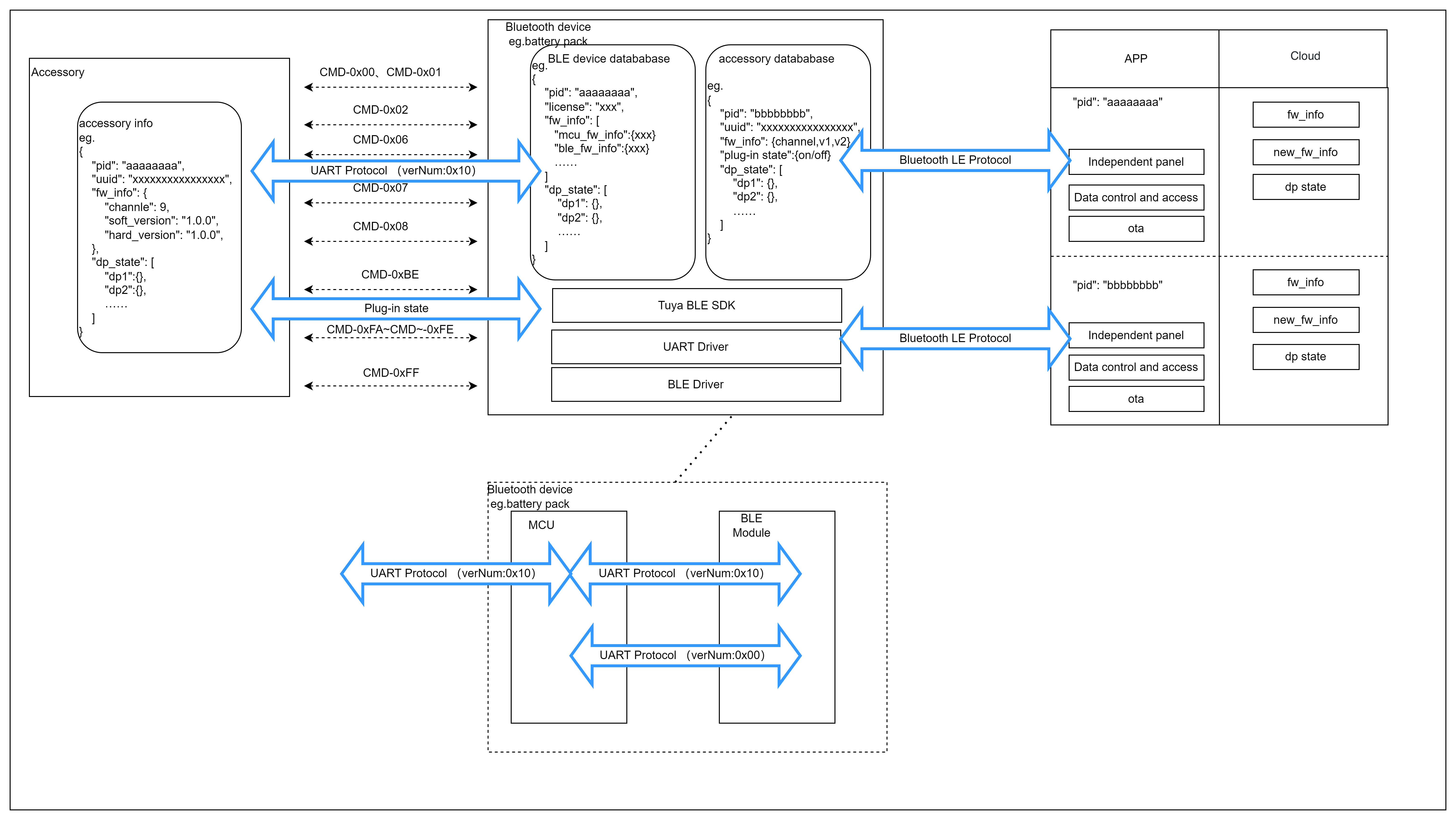
Take the battery pack as an example. It consists of an MCU and a generic Bluetooth module. The MCU and the Bluetooth module communicate through the UART. The Bluetooth module is connected to the mobile app and the cloud. The accessory communicates with the battery pack’s MCU via UART. After receiving serial data from the accessory, the MCU will forward the raw data to the Bluetooth module for processing. The Bluetooth module stores the accessory information, such as PID, UUID, and insertion status.
When the MCU detects an accessory insertion, it will notify the Bluetooth module. If the Bluetooth module is connected to the mobile app, it will then report the accessory information for cloud activation. After the accessory is activated, the Bluetooth module will create a separate communication channel for it. This allows the accessory to be accessed through an independent app panel.
Get started
Prepare hardware and software
-
Generic Bluetooth LE module
-
Module Debugging Assistant
Step 1: Select Bluetooth firmware
Select the generic Bluetooth firmware that supports extending MCU accessories.
-
Log in to the Tuya Developer Platform.
-
Click Create.
-
Determine the product category for your devices. For example, Electrical > Battery Pack.
-
Choose TuyaOS for smart mode.
-
Under the Custom Solution tab, select Battery Pack.
-
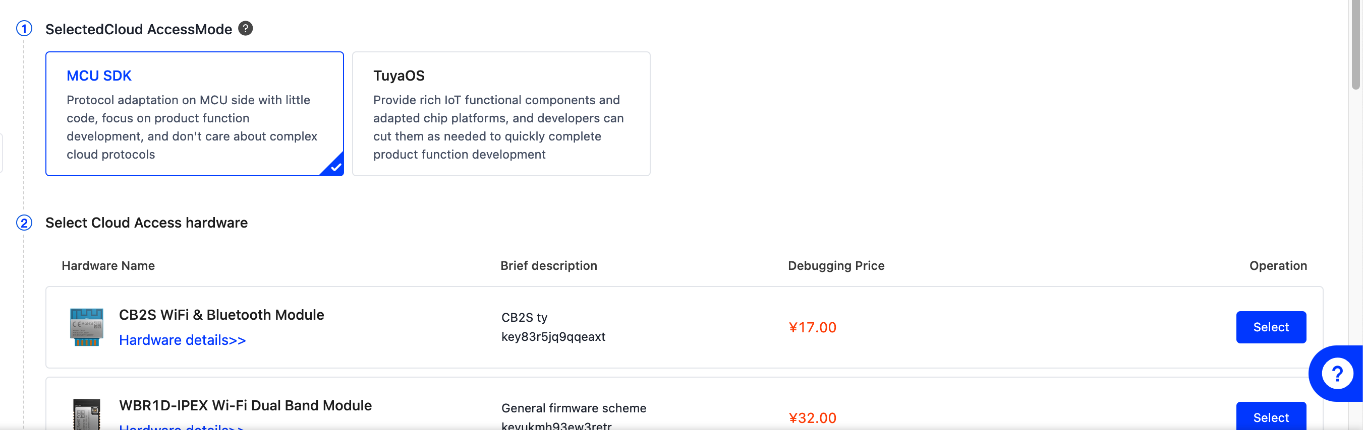
In Hardware Development, choose MCU SDK for cloud access mode.
Currently, the Telink series has been adapted for MCU accessory extension. The following is an incomplete list of deliverables that support this feature. If you cannot find the required deliverable, submit a service ticket to request listing it.
Step 2: Try out features
Respect the convention of using UART to establish connections between the Bluetooth module and the MCU, as well as between the MCU and the accessory. In the following sections, the Bluetooth module is referred to as the module. The accessory talks to the Bluetooth module with the MCU as the intermediary to pass raw data. To simplify debugging, use the Module Debugging Assistant to simulate both the role of the MCU and the accessory. The battery pack is used to describe the testing steps in the following sections.
-
By default, the Bluetooth module does not support accessories. You need to enable accessory support in the response to the MCU information query (0x01).
Example:
MCU to module: 55 AA 00 01 00 10 34 6B 78 36 68 6C 61 78 31 2E 30 2E 30 C2 01 01 BB (The C2 configuration item in the format of
C2 01 01indicates enabling accessory support)The change made to the configuration of accessory support takes effect after the device is reset and paired again.
-
With the Module Debugging Assistant, send accessory information to the module, including PID, UUID, and firmware information.
Example:
Accessory to MCU to module:
55 AA 10 01 00 23 10 74 75 79 61 31 32 33 34 35 36 37 38 39 61 62 63 00 08 72 64 67 61 72 67 78 31 07 09 01 00 00 01 00 00 43(UUID:tuya123456789abc, accessory PID:rdgargx1, accessory firmware information: channel ID 9, firmware version 1.0.0, hardware version 1.0.0) -
The battery pack’s MCU detects accessory insertion and synchronizes the status to the Bluetooth module. After an accessory is inserted, the module will report the accessory information to the mobile app for cloud activation. The accessory will be displayed on the app’s homepage and have its own panel and communication channel. If the accessory is not presented, you can refresh the homepage.
Example:
MCU to module:
55 AA 00 C2 00 02 00 01 C4Module to MCU:
55 AA 00 C2 00 01 00 C2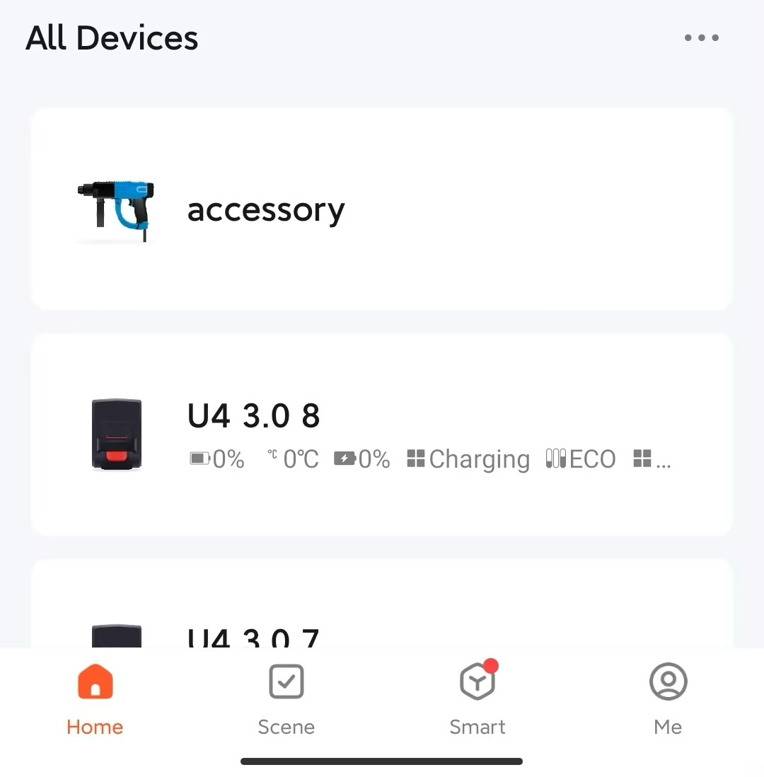
Excerpts from the MCU protocol
This protocol extends the capabilities of the MCU to the non-smart accessories.
Sync accessory status (0xC200)
- The connection status of a non-smart accessory depends on the Bluetooth status of the main device. When Bluetooth is disconnected, the accessory is offline.
- The MCU detects the presence of an accessory and notifies the Bluetooth module of the accessory status through this command for the module to update the status.
The MCU sends the following data.
| No. | Bytes | Field | Description |
|---|---|---|---|
| 0 1 |
2 | Header | 0x55 0xAA |
| 2 | 1 | Version number | 0x00 |
| 3 | 1 | Command (CMD) | 0xC2 |
| 4 5 |
2 | Data length (Len) | 0x00 0x02 |
| 6 | 1 | Subcommand | 0x00 |
| 7 | 1 | Status |
|
| 8 | 1 | CRC8 | Start from the header, add up all the bytes, and then divide the sum by 256 to get the remainder. |
The module returns the following data.
| No. | Bytes | Field | Description |
|---|---|---|---|
| 0 1 |
2 | Header | 0x55 0xAA |
| 2 | 1 | Version number | 0x00 |
| 3 | 1 | Command (CMD) | 0xC2 |
| 4 5 |
2 | Data length (Len) | 0x00 0x02 |
| 6 | 1 | Subcommand | 0x00 |
| 7 | 1 | Status |
|
| 8 | 1 | CRC8 | Start from the header, add up all the bytes, and then divide the sum by 256 to get the remainder. |
Query module’s MAC address (0xBE)
The MCU can use this command to query the MAC address of the Bluetooth module.
The MCU sends the following data.
| No. | Bytes | Field | Description |
|---|---|---|---|
| 0 1 |
2 | Header | 0x55 0xAA |
| 2 | 1 | Version number | 0x00 |
| 3 | 1 | Command (CMD) | 0xBE |
| 4 5 |
2 | Data length | 0x00 0x00 |
| 6 | 1 | CRC8 | Start from the header, add up all the bytes, and then divide the sum by 256 to get the remainder. |
The module returns the following data.
| No. | Bytes | Field | Description |
|---|---|---|---|
| 0 1 |
2 | Header | 0x55 0xAA |
| 2 | 1 | Version number | 0x00 |
| 3 | 1 | Command (CMD) | 0xBE |
| 4 5 |
2 | Data length | 0x00 0x06 |
| 6 to 11 | 6 | MAC | See the following table. |
| 12 | 1 | CRC8 | Start from the header, add up all the bytes, and then divide the sum by 256 to get the remainder. |
Suppose that the MAC address of the module is DC:23:66:11:22:33.
The MCU sends 55 AA 00 BE 00 00 BD to the module.
The module returns 55 AA 00 BE 00 06 DC 23 66 11 22 33 8E.
Accessory protocol
Each accessory must strictly follow the protocol to interact with the main device. If the device is connected using the MCU SDK solution, the MCU should pass the raw serial frames of protocol version 0x10 to the Bluetooth LE module for processing.
Frame format
| No. | Bytes | Field | Description |
|---|---|---|---|
| 0 1 |
2 | Header | 0x55 0xAA |
| 2 | 1 | Version number | 0x10 |
| 3 | 1 | Command (CMD) | The frame type. |
| 4 5 |
2 | Data length (Len) | Upper 8 bits Lower 8 bits |
| 6 to 6+Len-1 | Len | Data | / |
| 6+Len | 1 | CRC8 | Start from the header, add up all the bytes, and then divide the sum by 256 to get the remainder. |
All data greater than one byte is transmitted in big-endian format. The protocol version is fixed as 0x10, which is dedicated to the accessory protocol. You can identify the accessory command through 0x55AA10.
DP format
| Field | Bytes | Description |
|---|---|---|
| dp_id | 1 | The ID of a DP. |
| dp_type | 1 | The data type of a DP. |
| dp_data_len | 2 | The data length of a DP. |
| dp_data_value | dp_data_len | The data of a DP. |
The value range and description of dp_type (cloud defined):
| dp_type | Value | Bytes | Description |
|---|---|---|---|
| raw | 0x00 | 1 to 255 | The raw data in hexadecimal format. |
| bool | 0x01 | 1 | Boolean type. |
| value | 0x02 | 4 | Integer type. |
| string | 0x03 | 0 to 255 | String type. Its value can be empty. |
| enum | 0x04 | 1 | Enum type. |
| bitmap | 0x05 | 1/2/4 | Data greater than one byte is transmitted in big-endian format. |
Handshake (0x00)
After the accessory is connected to the main device, it should initiate a handshake. If the main device does not respond within three seconds, the accessory should retry until a response is received.
The accessory sends the following data.
| Field | Bytes | Description |
|---|---|---|
| Header | 2 | 0x55 0xAA |
| Version number | 1 | 0x10 |
| Command (CMD) | 1 | 0x00 |
| Data length (Len) | 2 | The total number of bytes in the data field. |
| CRC8 | 1 | Start from the header, add up all the bytes, and then divide the sum by 256 to get the remainder. |
Example:
55 AA 10 00 00 00 0F
The main device returns the following data.
| Field | Bytes | Description |
|---|---|---|
| Header | 2 | 0x55 0xAA |
| Version number | 1 | 0x10 |
| Command (CMD) | 1 | 0x00 |
| Data length (Len) | 2 | The total number of bytes in the data field. |
| Data | 1 | op_code:
|
| CRC8 | 1 | Start from the header, add up all the bytes, and then divide the sum by 256 to get the remainder. |
Example:
55 AA 10 00 00 01 00 10
Report device information (0x01)
-
If the main device responds to the handshake with
0x00, the accessory should send this command. -
If the receiving fails or times out for more than three seconds, the accessory should retry until the main device receives the message successfully.
The accessory sends the following data.
| Field | Bytes | Description |
|---|---|---|
| Header | 2 | 0x55 0xAA |
| Version number | 1 | 0x10 |
| Command (CMD) | 1 | 0x01 |
| Data length (Len) | 2 | The total number of bytes in the data field. |
| Data | 1 | UUID_LEN |
| 16 | UUID | |
| 1 | ID_TYPE: 0-Product ID (8 bytes) | |
| 1 | ID_LEN (8) | |
| 8 | ID | |
| 1 | FW_INFO_LEN: The length of firmware information. | |
| FW_INFO_LEN | FW_INFO_LIST: See the table below. | |
| CRC8 | 1 | Start from the header, add up all the bytes, and then divide the sum by 256 to get the remainder. |
FW_INFO_LIST: Firmware information list. Multiple firmware images are supported.
| 7 bytes | … | 7 bytes |
|---|---|---|
| FW_INFO1 | … | FW_INFOn |
FW_INFO:
| 1 byte | 3 bytes | 3 bytes |
|---|---|---|
| channel | soft_version | hard_version |
channel: The firmware channel ID, generated when you create the firmware on the Tuya Developer Platform. The valid values range from0 to 19.soft_version: The software version. For example,0x01 00 02indicates v1.0.2.hard_version: The hardware version. For example,0x01 00 02indicates v1.0.2.
Example 1: The accessory contains three firmware images: the accessory’s MCU firmware, extension firmware 1, and extension firmware 2.
55 AA 10 01 00 31 10 38 30 30 63 39 39 66 30 33 35 34 39 62 61 33 63 00 08 74 38 78 6A 61 77 76 73 15 09 00 00 01 00 01 00 0A 00 00 01 00 01 00 0B 00 00 01 00 01 00 12
Example 2: The accessory contains one accessory’s MCU firmware only.
55 AA 10 01 00 23 10 38 30 30 63 39 39 66 30 33 35 34 39 62 61 33 63 00 08 74 38 78 6A 61 77 76 73 07 09 00 00 01 00 01 00 DD
The main device returns the following data.
| Field | Bytes | Description |
|---|---|---|
| Header | 2 | 0x55 0xAA |
| Version number | 1 | 0x10 |
| Command (CMD) | 1 | 0x01 |
| Data length (Len) | 2 | The total number of bytes in the data field. |
| Data | 1 | Status:
|
| CRC8 | 1 | Start from the header, add up all the bytes, and then divide the sum by 256 to get the remainder. |
Example:
55 AA 10 01 00 01 00 11
Send working status (0x02)
The main device notifies the accessory of changes in working status.
The main device sends the following data.
| Field | Bytes | Description |
|---|---|---|
| Header | 2 | 0x55 0xAA |
| Version number | 1 | 0x10 |
| Command (CMD) | 1 | 0x02 |
| Data length (Len) | 2 | The total number of bytes in the data field. |
| Data | 1 | State:
|
| CRC8 | 1 | Start from the header, add up all the bytes, and then divide the sum by 256 to get the remainder. |
Example:
55 AA 10 02 00 01 01 13
The accessory returns the following data.
| Field | Bytes | Description |
|---|---|---|
| Header | 2 | 0x55 0xAA |
| Version number | 1 | 0x10 |
| Command (CMD) | 1 | 0x02 |
| Data length (Len) | 2 | The total number of bytes in the data field. |
| Data | 1 | Status:
|
| CRC8 | 1 | Start from the header, add up all the bytes, and then divide the sum by 256 to get the remainder. |
Send commands (0x06)
- For more information about DPs, see DP format.
- One command can contain data units of multiple DPs.
- The main device sends commands to the accessory asynchronously, corresponding to MCU reporting status.
The main device sends the following data.
| Field | Bytes | Description |
|---|---|---|
| Header | 2 | 0x55 0xAA |
| Version number | 1 | 0x10 |
| Command (CMD) | 1 | 0x06 |
| Data length (Len) | 2 | The total number of bytes in the data field. |
| Data | 4 | SN |
| 1 | dp1_id | |
| 1 | dp1_type | |
| 2 | dp1_len | |
| dp_len | dp1_data | |
| … | … | |
| 1 | dpN_id | |
| 1 | dpN_type | |
| 2 | dpN_len | |
| dpN_len | dpN_data | |
| CRC8 | 1 | Start from the header, add up all the bytes, and then divide the sum by 256 to get the remainder. |
Example:
55 AA 10 06 00 09 00 00 00 02 01 01 00 01 01 24
The accessory returns the following data.
None
Report status (0x07)
- For more information about DPs, see DP format.
- A piece of status data can contain data units of multiple DPs.
- This is an asynchronous command. The MCU uses it to report device status to the module, which can be triggered by three mechanisms.
- After the MCU executes the command received from the module, it reports the changed DP status to the module.
- When the MCU proactively detects status changes of DPs, it reports the changed DP status to the module.
- When the MCU receives the DP status query, it sends the status of all DPs to the module.
The accessory sends the following data.
| Field | Bytes | Description |
|---|---|---|
| Header | 2 | 0x55 0xAA |
| Version number | 1 | 0x10 |
| Command (CMD) | 1 | 0x07 |
| Data length (Len) | 2 | The total number of bytes in the data field. |
| Data | 4 | SN |
| 1 | FLAG | |
| 1 | time_type:
|
|
| 0 or M | The time parameter, which exists when time_type is 1. | |
| N | dp_point | |
| CRC8 | 1 | Start from the header, add up all the bytes, and then divide the sum by 256 to get the remainder. |
SN: The serial number.
FLAG:
0: Report data both to the cloud and the app panel.1: Report data to the cloud but not to the app panel.2: Report data to the app panel but not to the cloud.3: Not report data.
Example: Report data both to the cloud and the app panel, without including the time parameter.
55 AA 10 07 00 1B 00 00 00 FF 00 FF 01 01 00 01 00 03 02 00 04 00 00 01 F4 07 02 00 04 00 00 00 00 3D
The main device returns the following data.
| Field | Bytes | Description |
|---|---|---|
| Header | 2 | 0x55 0xAA |
| Version number | 1 | 0x10 |
| Command (CMD) | 1 | 0x07 |
| Data length (Len) | 2 | The total number of bytes in the data field. |
| Data | 4 | SN |
| 1 | FLAG | |
| 1 | Status:
|
|
| CRC8 | 1 | Start from the header, add up all the bytes, and then divide the sum by 256 to get the remainder. |
Example:
55 AA 10 07 00 01 00 17
Query status (0x08)
- The module asynchronously queries the status of all object-type DPs from the MCU. When the MCU receives a query, it reports the status of the respective DP through the command 0x07.
- The module sends a status query to the MCU when the following two events occur.
- The main device that is bound and connected detects that the MCU is restarted.
- The main device Bluetooth is reconnected after it goes offline.
The main device sends the following data.
| Field | Bytes | Description |
|---|---|---|
| Header | 2 | 0x55 0xAA |
| Version number | 1 | 0x10 |
| Command (CMD) | 1 | 0x08 |
| Data length (Len) | 2 | The total number of bytes in the data field. |
| Data | 1 | Num:
|
| Data | 0 or NUM | DP_LIST: The list of DP IDs to be queried. |
| CRC8 | 1 | Start from the header, add up all the bytes, and then divide the sum by 256 to get the remainder. |
Example:
55 AA 10 08 00 00 17
The accessory returns the following data.
None.
The accessory responds to this event by reporting DP data.
Query Bluetooth module’s MAC address (0xBE)
The MCU can use this command to query the MAC address of the Bluetooth module.
The MCU sends the following data.
| No. | Bytes | Field | Description |
|---|---|---|---|
| 0 1 |
2 | Header | 0x55 0xAA |
| 2 | 1 | Version number | 0x10 |
| 3 | 1 | Command (CMD) | 0xBE |
| 4 5 |
2 | Data length | 0x00 0x00 |
| 6 | 1 | CRC8 | Start from the header, add up all the bytes, and then divide the sum by 256 to get the remainder. |
The module returns the following data.
| No. | Bytes | Field | Description |
|---|---|---|---|
| 0 1 |
2 | Header | 0x55 0xAA |
| 2 | 1 | Version number | 0x10 |
| 3 | 1 | Command (CMD) | 0xBE |
| 4 5 |
2 | Data length | 0x00 0x06 |
| 6 to 11 | 6 | MAC | See the following table. |
| 12 | 1 | CRC8 | Start from the header, add up all the bytes, and then divide the sum by 256 to get the remainder. |
Suppose that the MAC address of the module is DC:23:66:11:22:33.
The MCU sends 55 AA 10 BE 00 00 CD.
The module returns 55 AA 10 BE 00 06 DC 23 66 11 22 33 9E.
Update process
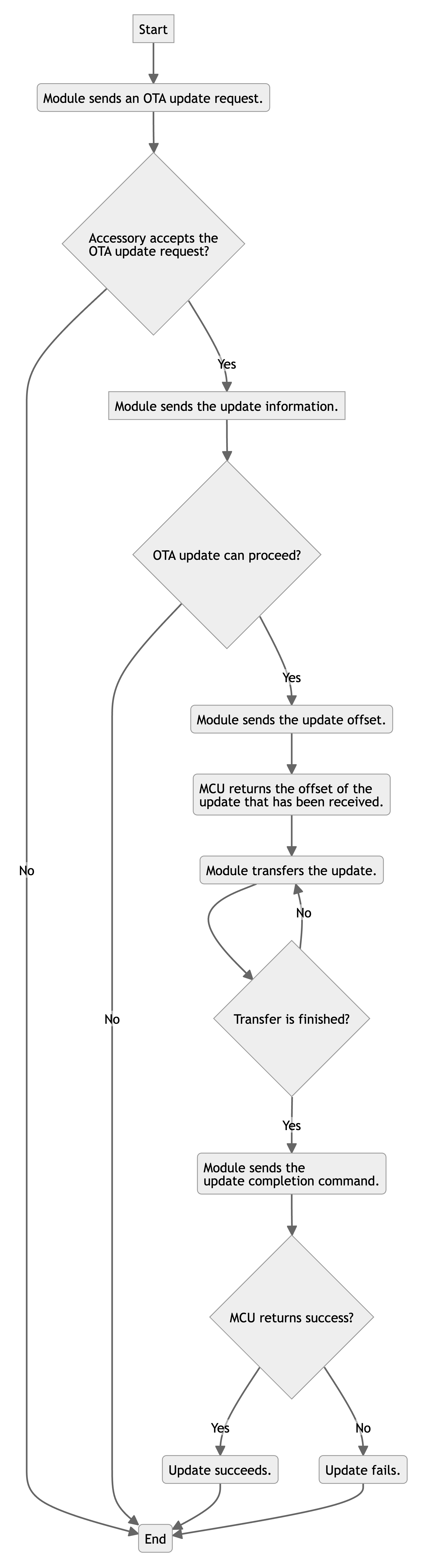
-->B(Module sends an OTA update request.) --> C{Accessory accepts the
OTA update request? --> --> | No | N(End) -->E{OTA update can proceed? --> | Yes | F(Module sends the update offset.) --> | No | N(End) -->G(MCU returns the offset of the
update that has been received.) -->H(Module transfers the update.) -->I{Transfer is finished? --> | Yes | J(Module sends the
update completion command.) --> | No | H(Module transfers the update.) -->K{MCU returns success? --> | Yes | L(Update succeeds.) --> | No | M(Update fails.) -->N(End) -->N(End);
```
Accessory update request (0xFA)
The main device sends an update request to the accessory to get the maximum length of a packet for serial transmission.
The main device sends the following data.
| Field | Bytes | Description |
|---|---|---|
| Header | 2 | 0x55 0xAA |
| Version number | 1 | 0x10 |
| Command (CMD) | 1 | 0xFA |
| Data length (Len) | 2 | The total number of bytes in the data field. |
| Data | 1 | TYPE |
| 2 | Len1 | |
| CRC8 | 1 | Start from the header, add up all the bytes, and then divide the sum by 256 to get the remainder. |
-
TYPE: The firmware channel ID, generated when you create the firmware on the Tuya Developer Platform. The firmware channel ID for the accessory’s MCU is typically 9, while for the extension firmware, it ranges from 10 to 19. -
Len1: The maximum length of a packet that can be transmitted over the serial port, in the unit of bytes.
The accessory returns the following data.
| Field | Bytes | Description |
|---|---|---|
| Header | 2 | 0x55 0xAA |
| Version number | 1 | 0x10 |
| Command (CMD) | 1 | 0xFA |
| Data length (Len) | 2 | The total number of bytes in the data field. |
| Data | 1 | TYPE |
| 1 | Flag | |
| 6 | Type_data: Version (4 bytes) + Len2 (2 bytes) |
|
| CRC8 | 1 | Start from the header, add up all the bytes, and then divide the sum by 256 to get the remainder. |
-
TYPE: The same as command sending. -
Flag:0x00indicates the update is accepted.0x01indicates the update is rejected. -
Version: The current firmware version. For example,0x00 01 00 02represents v1.0.2. -
Len1: The maximum length of a packet specified by the main device. -
Len2: The maximum length of a packet allowed by the accessory. IfLen1is less thanLen2,Len1prevails. Otherwise,Len2prevails.
Accessory update information (0xFB)
The accessory can use the information about the OTA update to decide whether to perform an update.
The main device sends the following data.
| Field | Bytes | Description |
|---|---|---|
| Header | 2 | 0x55 0xAA |
| Version number | 1 | 0x10 |
| Command (CMD) | 1 | 0xFB |
| Data length (Len) | 2 | The total number of bytes in the data field. |
| Data | 1 | TYPE |
| 8 | Product ID (PID) | |
| 4 | The firmware version. | |
| 16 | The MD5 hash. | |
| 4 | The file length. | |
| 4 | The CRC32 checksum. | |
| CRC8 | 1 | Start from the header, add up all the bytes, and then divide the sum by 256 to get the remainder. |
-
TYPE: The firmware channel ID, generated when you create the firmware on the Tuya Developer Platform. The channel ID for the accessory’s MCU is typically 9, while for the extension firmware, it ranges from 10 to 19. -
PID: The PID of the accessory. -
Firmware version: The version of firmware to be installed. For example,
0x00 01 00 02represents v1.0.2. -
MD5 hash: The MD5 value of the firmware update.
-
File length: The total length of the firmware update, in bytes.
-
CRC32 checksum: The CRC32 value of the firmware update.
The accessory returns the following data.
| Field | Bytes | Description |
|---|---|---|
| Header | 2 | 0x55 0xAA |
| Version number | 1 | 0x10 |
| Command (CMD) | 1 | 0xFB |
| Data length (Len) | 2 | The total number of bytes in the data field. |
| Data | 1 | TYPE |
| 1 | STATE | |
| 4 | The size of the update that has already been downloaded. | |
| 4 | The CRC32 checksum of the update that has already been downloaded. | |
| 16 | The MD5 hash value of the update that has already been downloaded. (Not used currently) | |
| CRC8 | 1 | Start from the header, add up all the bytes, and then divide the sum by 256 to get the remainder. |
TYPE: The firmware channel ID, generated when you create the firmware on the Tuya Developer Platform. The channel ID for the accessory’s MCU is typically 9, while for the extension firmware, it ranges from 10 to 19.
STATE:
-
0x00: The update is performed as expected. -
0x01: The received PID does not match the one written to the device. -
0x02: The update version is earlier than or equal to the current version. -
0x03: The update size exceeds the upper limit. -
Other fields: Reserved
- The accessory returns information about the update that has been downloaded to continue downloading from where it was interrupted.
- The main device calculates the CRC32 checksum of the update and then compares it to the value received.
- If the two match exactly, the app will change the start offset to the received data length in the following transmission request. Otherwise, the start offset is
0, meaning downloading from scratch.
- The resumable transfer also follows the normal update process, starting from initiating an update request. If the accessory is not activated and connected, the update status, if any, should be reset before starting the next update step.
Request the update offset (0xFC)
The main device sends the following data.
| Field | Bytes | Description |
|---|---|---|
| Header | 2 | 0x55 0xAA |
| Version number | 1 | 0x10 |
| Command (CMD) | 1 | 0xFC |
| Data length (Len) | 2 | The total number of bytes in the data field. |
| Data | 1 | TYPE |
| 4 | OFFSET | |
| CRC8 | 1 | Start from the header, add up all the bytes, and then divide the sum by 256 to get the remainder. |
-
TYPE: The firmware channel ID, generated when you create the firmware on the Tuya Developer Platform. The channel ID for the accessory’s MCU is typically 9, while for the extension firmware, it ranges from 10 to 19. -
OFFSET: Indicate where to start downloading the update.
The accessory returns the following data.
| Field | Bytes | Description |
|---|---|---|
| Header | 2 | 0x55 0xAA |
| Version number | 1 | 0x10 |
| Command (CMD) | 1 | 0xFC |
| Data length (Len) | 2 | The total number of bytes in the data field. |
| Data | 1 | TYPE |
| 4 | OFFSET | |
| CRC8 | 1 | Start from the header, add up all the bytes, and then divide the sum by 256 to get the remainder. |
-
TYPE: The same as command sending. -
OFFSET: The start offset specified by the accessory.
The start offset address specified by the accessory should take precedence over the one provided by the main device. The accessory-specified offset is usually less than the one provided by the main device.
Transfer the update (0xFD)
The main device sends the following data.
| Field | Bytes | Description |
|---|---|---|
| Header | 2 | 0x55 0xAA |
| Version number | 1 | 0x10 |
| Command (CMD) | 1 | 0xFD |
| Data length (Len) | 2 | The total number of bytes in the data field. |
| Data | 1 | TYPE |
| 2 | The packet ID. | |
| 2 | The length of the current packet n. | |
| 2 | The CRC16 checksum of the current packet. | |
| n | The payload of the current packet. | |
| CRC8 | 1 | Start from the header, add up all the bytes, and then divide the sum by 256 to get the remainder. |
TYPE: The firmware channel ID, generated when you create the firmware on the Tuya Developer Platform. The channel ID for the accessory’s MCU is typically 9, while for the extension firmware, it ranges from 10 to 19.
The packet ID starts from 0. The length of the current packet cannot exceed the specified maximum length of a packet.
The accessory returns the following data.
| Field | Bytes | Description |
|---|---|---|
| Header | 2 | 0x55 0xAA |
| Version number | 1 | 0x10 |
| Command (CMD) | 1 | 0xFD |
| Data length (Len) | 2 | The total number of bytes in the data field. |
| Data | 1 | TYPE |
| 1 | STATE | |
| CRC8 | 1 | Start from the header, add up all the bytes, and then divide the sum by 256 to get the remainder. |
TYPE: The firmware channel ID, generated when you create the firmware on the Tuya Developer Platform. The channel ID for the accessory’s MCU is typically 9, while for the extension firmware, it ranges from 10 to 19.
The return value of State.
-
0x00: Success -
0x01: Packet ID error. -
0x02: The data length does not match the expected one. -
0x03: CRC check failed. -
0x04: Other error codes.
Request the update result (0xFE)
The main device sends the following data.
| Field | Bytes | Description |
|---|---|---|
| Header | 2 | 0x55 0xAA |
| Version number | 1 | 0x10 |
| Command (CMD) | 1 | 0xFE |
| Data length (Len) | 2 | The total number of bytes in the data field. |
| Data | 1 | TYPE |
| CRC8 | 1 | Start from the header, add up all the bytes, and then divide the sum by 256 to get the remainder. |
TYPE: The firmware channel ID, generated when you create the firmware on the Tuya Developer Platform. The channel ID for the accessory’s MCU is typically 9, while for the extension firmware, it ranges from 10 to 19.
The accessory returns the following data.
| Field | Bytes | Description |
|---|---|---|
| Header | 2 | 0x55 0xAA |
| Version number | 1 | 0x10 |
| Command (CMD) | 1 | 0xFE |
| Data length (Len) | 2 | The total number of bytes in the data field. |
| Data | 1 | TYPE |
| 1 | STATE | |
| CRC8 | 1 | Start from the header, add up all the bytes, and then divide the sum by 256 to get the remainder. |
TYPE: The firmware channel ID, generated when you create the firmware on the Tuya Developer Platform. The channel ID for the accessory’s MCU is typically 9, while for the extension firmware, it ranges from 10 to 19.
The return value of State.
-
0x00: Success -
0x01: The total data length error. -
0x02: The data length does not match the expected one. -
0x03: Other error codes.
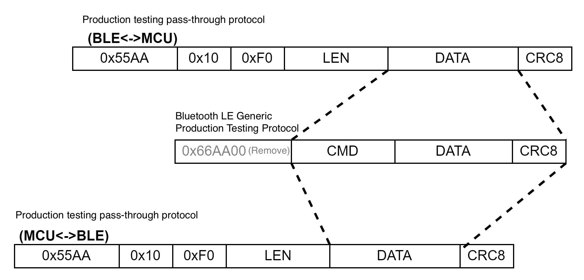
Testing data pass-through (0xF0)
Pass the raw data when an accessory is authorized wirelessly with a dongle through the battery pack.
The accessory or main device sends the following data.
| Field | Bytes | Description |
|---|---|---|
| Header | 2 | 0x55 0xAA |
| Version number | 1 | 0x10 |
| Command (CMD) | 1 | 0xF0 |
| Data length (Len) | 2 | The total number of bytes in the data field. |
| Data | n | See the authorization and testing protocol. |
| CRC8 | 1 | Start from the header, add up all the bytes, and then divide the sum by 256 to get the remainder. |
The main device or accessory returns the following data.
| Field | Bytes | Description |
|---|---|---|
| Header | 2 | 0x55 0xAA |
| Version number | 1 | 0x10 |
| Command (CMD) | 1 | 0xF0 |
| Data length (Len) | 2 | The total number of bytes in the data field. |
| Data | n | See the authorization and testing protocol. |
| CRC8 | 1 | Start from the header, add up all the bytes, and then divide the sum by 256 to get the remainder. |
FAQs
Q: How can I distinguish between the MCU integration protocol and the accessory integration protocol?
A:
The Bluetooth serial communication protocol specifies how the MCU and Bluetooth module interact through UART.
The Bluetooth accessory serial communication protocol specifies how the MCU and accessory interact through UART.
These two protocols can be distinguished by the protocol version number. The version number of the accessory protocol is 0x10, with the frame header 0x55AA10. When the MCU detects a protocol version of 0x10, it will send the raw serial data to the Bluetooth module for processing.
Q: What code logic should I add to the battery pack’s MCU to support accessories?
A:
The following logic is required:
- By default, the Bluetooth module does not support accessories. You need to enable accessory support in the response to the MCU information query (0x01).
- Detect the accessory insertion status and synchronize it to the Bluetooth module through the command 0xC200.
- When the MCU detects a protocol version of
0x10, it will send the raw serial data to the Bluetooth module for processing.
Q: Can a battery pack be used in tandem with multiple power tools?
A:
A battery pack can activate multiple power tools, but the panel only displays the most recently activated one. The UUID of the power tool must be unique and valid to ensure that the battery pack can activate the correct power tool.
After the power tool is replaced, the battery pack’s MCU should update the accessory information and synchronize the insertion status to the Bluetooth module for activation.
Q: How can I update multiple firmware images on the accessory?
A:
You can differentiate the firmware images using the TYPE field in the OTA update commands 0xFA through 0xFE. TYPE is the firmware channel ID, generated when you create the firmware on the Tuya Developer Platform.
Q: What are the common considerations?
A:
- After receiving the accessory information, the Bluetooth module will not activate the accessory until the MCU synchronizes the accessory insertion status.
- Each accessory must store the UUID authorized by Tuya.
Reference
If you have any problems with TuyaOS development, you can post your questions in the Tuya Developer Forum.
Is this page helpful?
YesFeedbackIs this page helpful?
YesFeedback


