YBLC5 Module Datasheet
YBLC5 is a low-power embedded Wi-Fi module that Tuya has developed. It consists of a highly integrated RF chip (ESP8285), a few peripherals, an embedded Wi-Fi network protocol stack, and rich library functions.
After a period of service, this module will become deprecated due to product upgrades and iterations, user requirements, production inventory, or other reasons. To improve the compatibility of your smart devices and minimize the impact on your use, Tuya continues to provide webpage documentation of deprecated modules, but no longer maintains or updates the documentation. The content herein is for reference only.
If you have any questions, submit a ticket to contact Tuya or consult Tuya’s account manager to request support. If you need similar substitute products, see CBLC5 Module Datasheet.
Overview
YBLC5 has an embedded low-power 32-bit CPU, 1-MB flash memory, 50-KB SRAM, and rich peripherals.
YBLC5 is an RTOS platform that integrates all function libraries of the Wi-Fi MAC and TCP/IP. You can develop embedded Wi-Fi products as required.
Features
-
Embedded low-power 32-bit CPU, which can also function as an application processor
-
The clock rate supports 80 MHz and 160 MHz
-
Working voltage: 3.0 to 3.6 V
-
Peripherals: 3 GPIOs and 1 UART
-
Wi-Fi connectivity
- 802.11 b/g/n
- Channels 1-14@2.4GHz(CH1-11 for US/CA, CH1-13 for EU/CN)
- Support WEP/WPA/WPA2/WPA2 PSK (AES) security mode
- Up to + 20dBm output power in 802.11b mode
- Support SmartConfig and AP network configuration manners for Android and IOS devices
- Solered external antenna
- Working temperature: -20℃ to 105℃
Applications
- Intelligent building
- Smart household and home appliances
- Smart socket and light
- Industrial wireless control
- Baby monitor
- Network camera
- Intelligent bus
Module interfaces
Dimensions and package
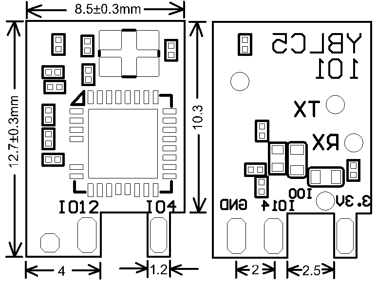
YBLC5 has two rows of pins with a 2-mm pin spacing.
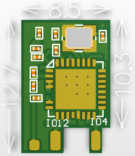
The YBLC5 dimensions are 8.5±0.35 mm (W)×12.7±0.35 mm (L) ×2.6±0.15 mm (H). The dimensions of YBLC5 are as follows:
Diagram of dimensions of YBLC5
Pin definition
Definitions on interface pins are shown below:
| Pin number | Symbol | I/O type | Function |
|---|---|---|---|
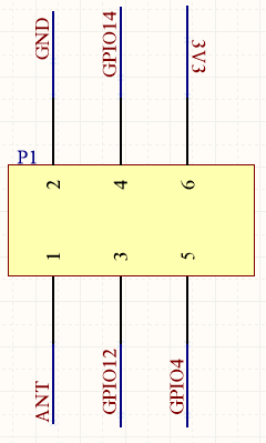
| 1 | ANT | - | RF antenna port, which is connected to an external antenna in a soldering manner |
| 2 | GND | P | Power supply reference ground |
| 3 | GPIO12 | I/O | GPIO_12 |
| 4 | GPIO14 | I/O | GPIO_14 |
| 5 | GPIO4 | I/O | GPIO_04 |
| 6 | VCC | P | Power supply pin (3.3V) |
Note: P indicates a power supply pin and I/O indicates an input/output pin.
Definitions on test points
The definitions of pins of YBLC5 are shown in the following table:
Descriptions on arrangement of pins of YBLC5:
| Pin number | Symbol | I/O type | Function |
|---|---|---|---|
| - | TP1 | Rst | It is only a module reset pin and cannot be used for clearing Wi-Fi network pairing information |
| - | TP2 | I/O | GPIO 0, used for the production test of the module |
| - | TP3 | U0TXD | User serial interface. When the module is powered on and enabled, there is information output from the serial interface, which is used for production test. |
| - | TP4 | U0RXD | User serial interface. When the module is powered on and enabled, there is information output from the serial interface, which is used for production test. |
Electrical parameters
Absolute electrical parameters
| Parameter | Description | Minimum value | Maximum value | Unit |
|---|---|---|---|---|
| Ts | Storage temperature | -40 | 125 | ℃ |
| VCC | Power supply voltage | -0.3 | 3.6 | V |
| ESD voltage (human body model) | TAMB-25℃ | - | 2 | KV |
| ESD voltage (machine model) | TAMB-25℃ | - | 0.5 | KV |
Normal working conditions
| Parameter | Description | Minimum value | Typical value | Maximum value | Unit |
|---|---|---|---|---|---|
| Ta | Working temperature | -20 | - | 105 | ℃ |
| VCC | Power supply voltage | 3.0 | 3.3 | 3.6 | V |
| VIL | I/O low-level input | -0.3 | - | VCC*0.25 | V |
| VIH | I/O high level input | VCC*0.75 | - | VCC | V |
| VOL | I/O low-level output | - | - | VCC*0.1 | V |
| VOH | I/O high-level output | VCC*0.8 | - | VCC | V |
| Imax | I/O drive current | - | - | 12 | mA |
Wi-Fi transmission power consumption
| Working status | Mode | Rate | Transmit power/Receive | Typical value | Unit |
|---|---|---|---|---|---|
| Transmit | 11b | 11Mbps | +17dBm | 220 | mA |
| Transmit | 11g | 54Mbps | +15dBm | 110 | mA |
| Transmit | 11n | BW20 MCS7 | +13dBm | 100 | mA |
Wi-Fi receiving power consumption
| Symbol | Working status | Mode | Typical value | Unit |
|---|---|---|---|---|
| IRF | 11b | 11Mbps | 76 | mA |
| IRF | 11g | 54Mbps | 76 | mA |
| IRF | 11n | MCS7 | 76 | mA |
Working power consumption
| Working mode | Working status, Ta = 25°C | Average value | Maximum value | Unit |
|---|---|---|---|---|
| Quick network connection state | The module is in the fast network connection state and the Wi-Fi indicator flashes fast | 80 | 415 | mA |
| Hotspot network configuration state | The module is in the hotspot network configuration state and the Wi-Fi indicator always flashes slowly | 90 | 451 | mA |
| Connected | The module is connected to the network and the Wi-Fi indicator is always on | 58.5 | 411 | mA |
| Disconnected | The module is disconnected and the Wi-Fi indicator is dark | 80 | 430 | mA |
RF features
Basic RF features
| Parameter | Description |
|---|---|
| Frequency range | 2.412 to 2.484 GHz |
| Wi-Fi standard | IEEE 802.11b/g/n (channels 1 to 14) |
| Data transmission rate | 11b: 1, 2, 5.5, 11 (Mbps) 11g: 6, 9, 12, 18, 24, 36, 48, 54 (Mbps) 11n: HT20 MCS 0 to 7 |
| Antenna type | Solered external antenna |
TX performance
TX performance
| Parameter | Minimum value | Typical value | Maximum value | Unit |
|---|---|---|---|---|
| Average RF output power, 802.11b CCK Mode 1M | - | 20 | - | dBm |
| Average RF output power, 802.11g OFDM Mode 54M | - | 17 | - | dBm |
| Average RF output power, 802.11n OFDM Mode MCS7 | - | 14 | - | dBm |
| Frequency error | -10 | - | 10 | ppm |
RX performance
RX sensitivity
| Parameter | Minimum value | Typical value | Maximum value | Unit |
|---|---|---|---|---|
| PER<8%, RX sensitivity, 802.11b CCK Mode 1M | - | -91 | - | dBm |
| PER<10%, RX sensitivity, 802.11g OFDM Mode 54M | - | -75 | - | dBm |
| PER<10%, RX sensitivity, 802.11n OFDM Mode MCS7 | - | -72 | - | dBm |
Antenna information
Antenna type
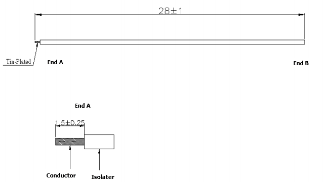
The module uses an external antenna which is soldered on the ANT pad of the module in a soldering manner.
An antenna with a length of 28 mm is recommended. For details, you can refer to the following figure:
Antenna interference reduction
To ensure the optimal Wi-Fi performance when the Wi-Fi module uses an external antenna, it is recommended that the antenna be at least 10 mm away from other metal parts.
Packaging information and production instructions
Mechanical dimensions
Recommended PCB packaging
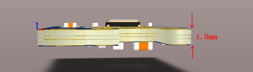
For distribution and definition of pins of the module, you can refer to the following figure. The thickness of the PCB is 1.0±0.1 mm.
The schematic diagram of YBLC5 shows pins and the thickness of the PCB:
Production instructions
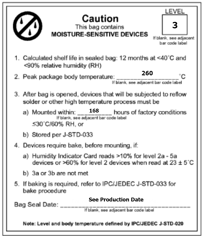
- For the Tuya in-line module, wave soldering is most preferred and manual soldering is less preferred. After being unpacked, the module must be soldered within 24 hours. Otherwise, it must be put into the drying cupboard where the RH is not greater than 10%; or it needs to be packaged under vacuum again and record the exposure time (the total exposure time cannot exceed 168 hours).
- Wave soldering devices and materials:
- Wave soldering equipment
- Wave soldering fixture
- Constant-temperature soldering iron
- Tin bar, tin wire, and flux
- Thermal profiler
- Baking devices:
- Cabinet oven
- Anti-electrostatic and heat-resistant trays
- Anti-electrostatic and heat-resistant gloves
- The module needs to be baked in the following cases:
- The packaging bag is damaged before unpacking.
- There is no humidity indicator card (HIC) in the packaging bag.
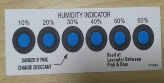
- After unpacking, circles of 10% and above on the HIC become pink.
- The total exposure time has lasted for over 168 hours since unpacking.
- More than 12 months have passed since the sealing of the bag.
- Baking settings:
- Temperature: 40°C and ≤ 5% RH for reel package and 125°C and ≤5% RH for tray package (please use the heat-resistant tray rather than a plastic container).
- Time: 168 hours for reel package and 12 hours for tray package.
- Alarm temperature: 50°C for reel package and 135°C for tray package.
- Production-ready temperature after natural cooling: < 36°C.
- Re-baking situation: If a module remains unused for over 168 hours after being baked, it needs to be baked again.
- If a batch of modules is not baked within 168 hours, do not use the wave soldering to solder them. Because these modules are Level-3 moisture-sensitive devices, they are very likely to get damp when exposed beyond the allowable time. In this case, if they are soldered at high temperatures, it may result in device failure or poor soldering.
- In the whole production process, take electrostatic discharge (ESD) protective measures.
- To guarantee the quality of products, you must pay attention to the following items: The amount of soldering flux, the height of the wave peak, whether the tin slag and copper content in the wave soldering tank exceed standards, whether the window and thickness of the wave soldering fixture are appropriate, and whether the wave soldering oven temperature curve is appropriate.
Recommended oven temperature curve and temperature
Set oven temperatures according to the following temperature curve of wave soldering. The peak temperature is 260°C±5°C.
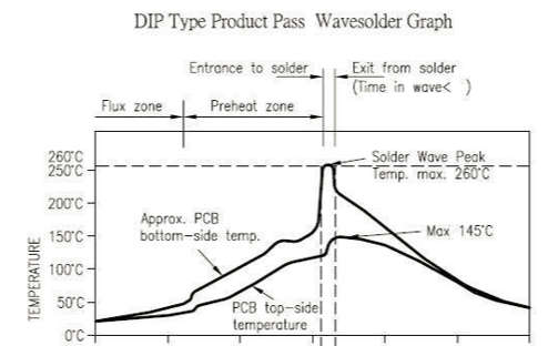
Recommended soldering temperature:
| Suggestions on oven temperature curve of wave soldering | Suggestions on manual soldering temperature | ||
|---|---|---|---|
| Preheat temperature | 80 to 130 °C | Soldering temperature | 360±20°C |
| Preheat time | 75 to 100s | Soldering time | <3s/point |
| Peak contact time | 3 to 5s | NA | NA |
| Temperature of tin cylinder | 260±5°C | NA | NA |
| Ramp-up slope | ≤2°C/s | NA | NA |
| Ramp-down slope | ≤6°C/s | NA | NA |
Storage conditions
Storage conditions for a delivered module:
-
The moisture-proof bag is placed in an environment where the temperature is below 40°C and the relative humidity is lower than 90%.
-
The shelf life of a dry-packaged product is 12 months from the date when the product is packaged and sealed.
-
There is a humidity indicator card (HIC) in the packaging bag.
Is this page helpful?
YesFeedbackIs this page helpful?
YesFeedback


