Bluetooth Mesh Lighting SDK
This topic describes the demo for developing Telink TLSR825x-based Bluetooth mesh lighting products and how to set up the debugging environment.
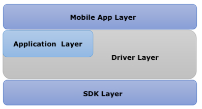
The following diagram shows the development architecture of lighting products.
Things to note
- Do not change the original denotation of any control commands.
- Do not add any control commands other than these mentioned in this topic. If you have specific requirements for control commands, contact Tuya’s technical support.
Data point (DP) introduction
Standard Bluetooth mesh commands
Tuya Developer Platform takes standard Bluetooth mesh commands as custom commands. When the mobile app and gateway communicate with the device, the custom commands will be converted into standard Bluetooth mesh commands.
Note: The standard DP function for Bluetooth mesh is
void tuya_mesh_data_recv_callback(uint16_t src_addr, uint16_t dst_addr, uint32_t opcode, uint8_t *data, uint16_t data_len, uint8_t ttl). For more information about the standard Bluetooth mesh commands, see Mesh Model Specification.
| Tuya's definition |
Mesh model | Name |
|---|---|---|
| 1 | Generic OnOff (0x0282) | On/Off |
| 3 | Light Lightness Actual (0x4c82) | Brightness |
| 4 | Light CTL Temperature (0x6482) | Color temperature |
| 5 | Light HSL (0x7682) | Colored light |
Tuya’s DP definition
-
DP IDs 1 to 30 represent generic features that apply to most product categories. These DP IDs are unique.
-
DP IDs 31 to 50 represent newly introduced features that apply to most product categories. These DP IDs are unique.
-
DP IDs 51 to 100 represent features that apply to specific product categories.
-
DP IDs 101 to 200 represent user-defined features that apply to custom solutions.
-
DP IDs 201 to 250 represent system features that can be reused for electrical products and sensors.
Note: You can add the custom DP in the function
void app_tuya_vendor_light_dp_data(u8 *par, int par_len).
| Tuya’s DP definition | Feature name | Description |
|---|---|---|
| 2 | Mode | Switch between lighting modes, such as white light, colored light, scenes, and music sync. |
| 6 | Scene | |
| 7 | Countdown | |
| 8 | Music sync | The mobile app sends the music-based HSV value to the light. |
| 33 | Power-off memory | 0x00: Restore to initial defaults. 0x01: Restore to the state before the shutdown. 0x02: Restore to the user-defined state (HSV, brightness, and temperature). |
| 34 | Do not disturb (DND) | |
| 100–200 | Custom DP | You can add custom DPs for features that are not supported by standard DPs. |
Note: The raw protocol for DP
6scene and DP8music sync is relatively long, which is not friendly to Bluetooth mesh. Tuya compresses the protocol in the application and gateway layers. When the device receives these two DPs, it needs to decompress the protocol before using it. This step has been implemented in the SDK.
DP of scene
Raw data (same as the scene data of the Wi-Fi protocol)
-
Data type: string
-
Value:
0011223344445555666677778888Value Description 00 The scene number 11 The interval for transitions between units (0–100) 22 The interval between each unit (0–100) 33 The unit change mode (static, gradient, and jumping) 4444 H (hue: 0–360, 0x0000–0x0168) 5555 S (saturation: 0–1000, 0x0000–0x03E8) 6666 V (value: 0–1000, 0x0000–0x03E8) 7777 Brightness (0–1000, 0x0000–0x03E8) 8888 Color temperature (0–1000, 0x0000–0x03E8) Note: The scene number indicates the number of units in one scene. Up to eight units are allowed.
-
The compressed Bluetooth mesh protocol
Common header The first unit 0000 11xx x222 2222 Colored light 3xx4 5566 4444 4444 5555 5555 6666 6666 White light 3xxx 4455 4444 4444 5555 5555 xxxx xxxx Value Description 0 The scene number: a 4-bit value, ranging from one to eight. 1 The unit change mode: a 2-bit value, representing static, gradient, or jumping mode. 2 The interval between each unit: a 7-bit value, ranging from 0 to 100, which shares the same data format with the interval for transitions between units. 3 Color mode: a 1-bit value, which can be 0 (white light) or 1 (colored light).
The data of the scene unit varies depending on color modes.Colored light 4 Hue: a 9-bit value. Colored light 5 Saturation: a 10-bit value. Colored light 6 Value: a 10-bit value. White light 4 Brightness: a 10-bit value. White light 5 Color temperature: a 10-bit value. White light 6 Null
Music sync
Raw data (same as the scene data of the Wi-Fi protocol)
-
Data type: string
-
Value:
011112222333344445555Value Description 0 The change mode ( 0: jumping.1: gradient.)1111 H (hue: 0–360, 0x0000–0x0168) 2222 S (saturation: 0–1000, 0x0000–0x03E8) 3333 V (value: 0–1000, 0x0000–0x03E8) 4444 Brightness (0–1000, 0x0000–0x03E8) 5555 Color temperature (0–1000, 0x0000–0x03E8) -
The compressed Bluetooth mesh protocol
1st byte 2nd byte 3rd byte 4th byte 01xx 2233 1111 1111 2222 2222 3333 3333 Value Field Length
(byte)Description 0 The change mode 1 8-bit value: 0HxxSSVV
For the most significant bit, 0 indicates jumping and 1 indicates gradient.1 H 1 The value ranges from 0 to 360 and 360 is 9-bit. 8 bits make 1 byte, so the 1 bit is borrowed from the value of change mode as the most significant bit. 2 S 1 The value ranges from 0 to 1,000 and 1,000 is 10-bit. 8 bits make 1 byte, so the 2 bits are borrowed from the value of change mode as the most significant bit. 3 V 1 The value ranges from 0 to 1,000 and 1,000 is 10-bit. 8 bits make 1 byte, so the 2 bits are borrowed from the value of change mode as the most significant bit.
Commands for remote controls
The remote controls send DP commands with the function void ty_light_remote_dp_data(u8 * par, int par_len).
| Tuya-defined command |
Name | Description |
|---|---|---|
| 0x81 | Subscribe to remote controls | |
| 0x83 | Brightness | Adjust the brightness using the remote controls. |
| 0x87 | Add favorites | |
Directory structure
You can download the SDK and demo tuya_smesh_sdk_tlsr825x_light from GitHub. The following table provides an introduction to files included in the SDK.
| File name | File introduction | Note |
|---|---|---|
| app_common.c | The common features, including mobile app initialization, program running, and DP data processing. | The main source code file. |
| app_factory_test.c | Production test program. | The program of Tuya's standard production test. Generally, do not modify this file. |
| app_light_cmd.c | Set and read lighting commands. | Set and read a bunch of lighting features such as lighting modes, brightness, and color temperature. |
| app_light_control.c | Control lights and save parameters. | The light can work based on the parameters specified in the function app_light_cmd.c. |
| app_light_prompt.c | Indicator for device pairing. | It is used to indicate unpaired lights. |
| app_light_uart.c | Serial communication. | Parse the data related to the lighting application in the app_uart.c. For more information, see Bluetooth Mesh General Serial Protocol. |
| app_rssi.c | Read the received signal strength indicator (RSSI) using a dongle. | Determine whether to carry out the production test based on the measured signal strength. |
| app_uart.c | The general serial protocol, data initialization and processing for production test. | It is used for firmware flashing and authorization or serial communication with the MCU. |
| tuya_node_init.c | Initialization of mesh network to set or read parameters such as capabilities and product ID (PID). | The program of Tuya's standard initialization. Generally, do not modify this file. |
| ty_fifo.h | First-in and first-out (FIFO) component. | Called by the UART layer. |
| ty_gpio_base_test.h | GPIO test component. | |
| ty_light_basis_hw_timer.h | Hardware timer component. | 10-ms interrupt for light gradient. |
| ty_light_basis_sw_timer.h | Event callback component. | Called by ty_light_basis_sw_timer_start. |
| ty_light_basis_soc_gpio.h | I/O initialization read-write component. | Map the GPIOs specified on the Tuya Developer Platform to the actual GPIO numbers. |
| ty_light_basis_tools.h | Common tool component. | |
| ty_light_cfg.h | JSON initialization component for lights-related data. | |
| ty_light_driver_set.h | PWM or I2C component for lighting driver setting. | ty_ty_light_driver_set_rgbcw directly controls the value of RGB and cool and warm white (RGBCW) (0–20,000). |
| ty_light_gradual.h | Light gradient component. | |
| ty_light_json.h | JSON read component. | |
| ty_light_mdev.h | Final test component (aging test included). | |
| ty_light_remote.h | Remote controls component. | |
| ty_light_save.h | Data storage component. | |
| ty_nv.h | Underlying flash storage component. | |
| ty_light_sence.h | Light scene component. | |
| ty_rssi_base_test.h | Underlying RSSI test component. | |
| ty_string_op.h | String conversion to or from hexadecimal component. | |
| ty_timer_event.h | Timer component for initializing, running, adding, and deleting timer tasks. | The function is ty_timer_event_add. The returned value can be 0, -1, or positive numbers. 0: loop execution. -1: stoping execution. positive numbers: continuing execution after the timer is updated. |
| ty_uart_cmd_sever_for_factory_test.h | Underlying protocol processing component for production test. |
Main functions
| File name | Function | Description | Notes |
|---|---|---|---|
| app_common.c | void mesh_app_init(void) | Logic initialization in the application layer. | |
| app_common.c | void mesh_main_run(void) | Scheduled logic execution in the application layer. | |
| app_common.c | void mesh_factory_reset(void) | This function is called before the device reset, in order to clear application data stored in the flash memory. | |
| app_common.c | void app_tuya_mdev_test(uint8_t is_Authorized, uint8_t rssi) | The callback for firmware flashing and authorization. Generally, do not modify this file. | |
| app_common.c | void mesh_state_callback(mesh_state_t stat) | This function is called when the mesh status changes, in order to notify the application layer. You can view which information is reported in mesh_state_t. | |
| app_common.c | void tuya_mesh_data_recv_callback(uint16_t src_addr, uint16_t dst_addr, uint32_t opcode, uint8_t *data, uint16_t data_len, uint8_t ttl) | The callback for receiving data from the mobile app. Take care of this important function. src_addr[in]: data source address. dst_addr[in]: data destination address. opcode[in]: command. data[in]: data point. data_len[in]: data length. ttl[in]: the remaining number of times of data forwarding. |
|
| app_common.c | void mesh_oem_config_init(void) | Read flash or JSON configuration file. | |
| app_light_control.c | OPERATE_LIGHT app_light_ctrl_proc(void) | The light control function. | |
| app_light_control.c | void app_light_ctrl_loop(void) | This function runs in void mesh_main_run(void) to schedule light control tasks. | |
| app_light_control.c | OPERATE_LIGHT app_light_real_time_ctrl_proc(void) | The real-time light control for music sync. | |
| app_light_prompt.c | void app_light_ctrl_prompt_start(void) | This function is used to enable the indicator during device pairing. | |
| app_light_prompt.c | void app_light_ctrl_prompt_stop(void) | This function is used to disable the indicator during device pairing. | |
| app_uart.c | void app_uart_init(void) | Initialization of serial port, FIFO, data storage, production test, and communication with the MCU. | |
| app_uart.c | void app_uart_run(void) | This loop function is placed in the FIFO to read serial data. | These two loop functions app_factory_test_run(); and uart_server_run(); run in this loop function. uart_server_run(); can parse data in FIFO and call corresponding processing functions. |
| app_uart.c | static void app_uart_server_run(void) | This function can parse the serial data in FIFO based on the serial protocol and get the valid data frame. Then, it sends data to the production test data processing function app_factory_test_cmd(cmd,&buf[F_DATA],len) and serial data processing function ty_uart_cmd_server.receive_cmd(u8 cmd, u8 fur, u8 *para, u8 len) accordingly. | In the head, A5 5A indicates data from the MCU. 66 AA indicates data from the host for the production test. |
| app_uart.c | int app_mesh_uart_write(u8 fur, u8 *params, u8 len) | This function can send the light commands or status in the mesh network to the MCU. | Whether to send commands or messages to the MCU depends on the return value of the ty_uart_cmd_server_get_txtomcu_flag() whose value is specified through ty_uart_cmd_server_set_txtomcu_flag(bool flag). |
| app_uart.c | void app_mesh_uart_upload(u8 *params, u8 len, u8 is_group) | The MCU sends raw DP data. | |
| app_uart.c | void app_mesh_uart_read(u8 fur, u8 *params, u8 len) | The MCU reads the light features, scene IDs, scene information, countdown, and mesh status. | |
| app_uart.c | void app_mesh_uart_ctl(u8 fur, u8 *params, u8 len) | The MCU controls the light features, scene IDs, scene actions, countdown, and Bluetooth mesh network reset. | |
| tuya_sigmesh_hal.c | void tuya_mesh_node_init(node_info_t *node_info) | Initialization of mesh nodes. Capabilities are configured in node_info[in]. | Device initialization, which must be called. |
| tuya_sigmesh_hal.c | void tuya_mesh_data_send(uint16_t src_addr, uint16_t dst_addr, uint32_t opcode, uint8_t *data, uint16_t data_len, uint16_t appkey_idx, uint8_t is_rsp) | The API for sending mesh data. src_addr[in]: data source address. dst_addr[in]: data destination address. opcode[in]: command. data[in]: data point. data_len[in]: data length. appkey_idx[in]: the used app_key. is_rsp[in]: Determine it is a request for DP status or an actively initiated command. |
|
| tuya_sigmesh_hal.c | void tuya_primary_ele_addr_set(uint16_t addr, int save) | Set the unicast addr of the light. addr[in]: the address of the light. save[in]: specifying whether to store data in the flash memory. |
|
| tuya_sigmesh_hal.c | uint16_t get_primary_ele_addr(void) | Get the unicast addr of the light. | |
| tuya_sigmesh_hal.c | void tuya_mesh_devkey_set(uint8_t *key) | Initiate updates of the devkey. | |
| tuya_sigmesh_hal.c | void tuya_mesh_network_reset_with_restore(uint16_t restore_time_s) | Remove the light from the network, restore it to pending pairing, and set a timeout for pairing. In the case of timeout, the light connects to the last connected network. | |
| tuya_sigmesh_hal.c | void tuya_mesh_rf_power_set(TUYA_RF_Power level) | Set the transmitter power. | |
| tuya_sigmesh_hal.c | void tuya_mesh_uuid_set(uint8_t *uuid) | Interface for UUID update. | |
| tuya_sigmesh_hal.c | void tuya_gatt_adv_beacon_enable(uint8_t enable) | Enable beacon broadcasting. | |
| tuya_sigmesh_hal.c | uint8_t get_if_prov_success(void) | Get the light pairing status. | |
| fast_provision_model.c | int mesh_reset_network(u8 provision_enable, u16 recover_time_s) | Remove the light from the network and restore it to pending pairing. | |
| tuya_node_init.c | void tuya_pid_set(uint8_t *pid) | Interface for PID update. If it is not called, the authorized PID will be used by default. | A 8-byte PID string. |
| tuya_node_init.c | void app_tuya_mesh_category_set(uint16_t mesh_category) | Configure the capabilities of the light. | |
| hal_hw_timer.c | OPERATE_LIGHT ty_light_basis_hw_timer_start(IN u32 uiCycleUs, IN void* pCallback) | This function is used to enable hardware timer tasks for the light gradient. | |
| hal_hw_timer.c | OPERATE_LIGHT ty_light_basis_hw_timer_stop(void) | This function is used to disable hardware timer tasks for the light gradient. | |
| ty_light_basis_sw_timer.c | OPERATE_LIGHT ty_light_basis_sw_timer_start(IN u8 ucTimerID, IN u32 uiCycleMs, IN void* pCallback); | This function is used to enable software timer tasks for light control. | |
| ty_light_basis_sw_timer.c | OPERATE_LIGHT ty_light_basis_sw_timer_stop(IN u8 ucTimerID); | This function is used to disable software timer tasks for light control. | |
| ty_light_basis_sw_timer.c | void ty_light_basis_sw_timer_handler(void); | Timer task processing. | |
| ty_light_driver_set.c | OPERATE_LIGHT ty_light_driver_set_init(IN DRIVER_CONFIG_T *pLightConfig); | Driver initialization. Three modes are available. PwmInit Sm2135Init tSm16726bInit |
|
| ty_light_gradual.c | void ty_light_gradual_hw_timer_handler(void); | Timer tasks for light gradient. | |
| ty_light_remote.c | void ty_light_remote_dp_data(u8 * par, int par_len); | Remote controls processing. | |
| ty_light_scene.c | void ty_light_scene_cmd_sync(u8 uint_num) | Scene sync. | |
| ty_light_scene.c | void ty_light_scene_ctrl_change_start(IN u32 uiChangeTimeMs) | Change the scene when the scheduled time is up. | |
| ty_light_scene.c | OPERATE_LIGHT ty_light_scene_ctrl_change(OUT bool *pCycleEnable, OUT u32 *pCycleTimeMs) | Convert the scene command to the value of RGB and cool and warm white. |
JSON file introduction
Tuya provides JSON templates for your reference.
- 1c_bt3l_pwm_V1.0.json
- 2cw_bt3l_pwm_V1.0.json
- 3rgb_bt3l_pwm_V1.0.json
- 3rgb_bt3l_sm726eb_V1.0.json
- 3rgb_bt3l_sm2135e_V1.0.json
- 4rgbc_bt3l_pwm_V1.0.json
- 4rgbc_bt3l_sm726eb_V1.0.json
- 4rgbc_bt3l_sm2135e_V1.0.json
- 5rgbcw_bt3l_pwm_V1.0.json
- 5rgbcw_bt3l_sm726eb_V1.0.json
- 5rgbcw_bt3l_sm2135e_V1.0.json
| Type | JSON name | Name | Editing required |
Description |
|---|---|---|---|---|
| json head | name | Firmware identifier | Yes | Create a firmware identifier on the Tuya Developer Platform. The firmware name must be consistent with the one you specified on the Tuya Developer Platform. |
| description | Feature configuration | Optional | Used for firmware description. | |
| version | Firmware version | Yes | The version number is in the format of x.x. | |
| ic | Chip model | No | tlsr825x | |
| hardware | Network module | No | TYBT3L | |
| log | Debugging logs | Optional | Set the value to 1 for log printing. This value must be 0 for the final firmware. |
|
| oem | Firmware type | No | The value must be 0. | |
| json_config | JSON configuration | No | The value must be 0. | |
| kind | Device capability | No | Keep the defaults. | |
| pid | Product ID (PID) | Yes | Set the value to the PID of your product. | |
| vendorid | Product category information | Yes | 1. Cool white light (C): 1011 2. Cool and warm white light (CW): 1012 3. Colored light (RGB): 1013 4. Cool white and colored light (RGBC): 1014 5. White and colored light (RGBCW): 1015 |
|
| power_reset_cnt | Number of resets | No | Keep the defaults. | |
| power_reset_time | Reset time | Optional | The light is powered off after a certain time, which is taken as power on/off once. The default value is five seconds. | |
| power_reset_recover_time | Network recovery time | Optional | After power reset, the time specified to restore the network without pairing again or power on/off. | |
| local_control | Local control | No | Keep the defaults. | |
| Macro | light_cfg_init_param_check | Parameter check in initialization | No | Keep the default value 0. |
| light_cfg_prod_driver_need_init | Re-initialization of parameters for production test | No | Keep the default value 0. | |
| light_cfg_3in1_save | Storage method | No | Keep the default value 0. | |
| light_cfg_remote_enable | Specify whether to support mesh remote controls. | Optional | 0: not support. 1: support. |
|
| light_cfg_uart_enable | Specify whether to support serial communication. | Optional | 0: not support. 1: support. For more information, see Bluetooth Mesh General Serial Protocol. |
|
| Jsonver | Version configuration | No | Keep the defaults. | |
| category | Device type | Yes | Set it same as the vendorid. | |
| module | Module model | Yes | BT8C Set the value to BT3L for non-BT8C modules. |
|
| cmod | Light solution | Yes | 1. Cool white light (C) 2. Cool and warm white light (CW) 3. Colored light (RGB) 4. Cool white and colored light (RGBC) 5. White and colored light (RGBCW) |
|
| dmod | Light driver | Yes | 0: PWM 1: SM16726B 2: SM2135E |
|
| cwtype | Color temperature driver | Yes | 0: cool and warm white (CW) 1: correlated color temperature (CCT) |
|
| onoffmode | On/off gradient | Yes | 0: Gradient is provided when the light is turned on/off. 1: Gradient is not provided when the light is turned on/off. |
|
| pmemory | Power-off memory | Yes | 0: power-off memory disabled 1: power-off memory enabled |
|
| defcolor | Default light color | Yes | Colored light: RGB White light: cool white. |
|
| defbright | Default brightness | Yes | The value ranges from 10 to 100. | |
| deftemp | Default color temperature | Yes | The valid range is 0 to 100 when defcolor is cool white. |
|
| cwmaxp | The max power of the mix of cool and warm white. | Yes | The value ranges from 100 to 200 with a pitch of 10 and defaults to 100. |
|
| brightmin | The min value of white light | Yes | The value ranges from 1 to 100 with a pitch of 1. | |
| brightmax | The max value of white light | Yes | The value ranges from 1 to 100 with a pitch of 1. | |
| colormin | The min value of colored light | Yes | The value ranges from 1 to 100 with a pitch of 1. | |
| colormax | The max value of colored light | Yes | The value ranges from 1 to 100 with a pitch of 1. | |
| wfcfg | Trigger for the first-time pairing. | Yes | spcl: flickering after manual toggling of pairing mode. spcl_auto: flickering on power-on and then steady on. |
|
| remdmode | Pairing indication | Yes | 0: fading in and out in a rhythmic fashion (breathing effect) 1: flickering |
|
| rstmode | Trigger for pairing | No | The value defaults to 0. | |
| rstnum | Number of times of power on/off to reset | Yes | The value ranges from 3 to 10 with a pitch of 1. | |
| rstcor | Color of pairing indication | Yes | Colored light: RGB White light: cool white. |
|
| rstbr | Brightness of pairing indication | Yes | The value ranges from 10 to 100. | |
| rsttemp | Color temperature of pairing indication | Yes | The valid range is 0 to 100 when rstcor is cool white. |
|
| pairt | Duration of pairing indication | Yes | The value ranges from 6 to 600. 6 is recommended. Note that the pairing operation will suspend during the breathing effect. |
|
| prodagain | Repeat production test 1 | Yes | 0: not support. 1: support. |
|
| cagt | The duration of aging test for cool white light | Yes | In minutes. | |
| wt | The duration of aging test for warm white light | Yes | In minutes. | |
| rgbt | The duration of aging test for colored light | Yes | In minutes. | |
| colorpfun | The power limit of the mix of colored light | Yes | 0: no limits 1: limits specified |
|
| colormaxp | The max power of the mix of colored light | Yes | The value ranges from 100 to 200. | |
| notdisturb | Do not disturb (DND) mode | Yes | 0: DND disabled. 1: DND enabled. |
|
| PWM | pmwhz | PWM frequency | Yes | The value ranges from 500 to 20,000 with a pitch of 100. |
| r_pin/g_pin/ b_pin/c_pin/ w_pin |
RGBCW pin | Yes | Specify the value for 0 to 14 fields. The pin mapping is the following: 0: GPIO_PB1 1: GPIO_PB7 2: GPIO_PB5 3: GPIO_PB4 4: GPIO_PA0 6: GPIO_PC0 7: GPIO_PC2 8: GPIO_PC3 9: GPIO_PD2 10: GPIO_PD7 11: GPIO_PC4 12: GPIO_PB0 13: GPIO_PC5 14: GPIO_PC1 |
|
| r_lv/g_lv/ b_lv/c_lv/ w_lv |
Active level | Yes | The value defaults to 1. The value set for all pins must be the same. 1: The light is on when the voltage is high. 0: The light is on when the voltage is low. |
|
| I2C driver | iicr/iicg/iicb /iicc/iicw |
RGBCW channel | Yes | Set this value to 01234. |
| iicscl | I2C SCL pin number | Yes | The value must be specified for I2C driver. | |
| iicsda | I2C SDA pin number | Yes | The value must be specified for I2C driver. | |
| ctrl_pin | The control pin | Yes | Required value for SM16726B. | |
| ctrl_lv | Level control configuration | Yes | Required value for SM16726B. 1: active high. 0: active low. |
|
| campere | The max current of SM2135 colored light output | Yes | Required value for SM2135E. The value ranges from 10 to 45 with a pitch of 5 and defaults to 20. |
|
| wampere | The max current of SM2135 white light output | Yes | Required value for SM2135E. The value ranges from 10 to 80 with a pitch of 5 and defaults to 30. |
|
| crc | Check | No | This parameter will not be verified so value editing is not necessary. |
Debugging operation
Environment setup
This section uses Telink’s Bluetooth chip as an example to describe debugging environment setup on Windows.
-
Check out IDE for TLSR8 Chips and install Telink IDE on your computer.
-
Copy
doc\tools\jq-win64.exetoC:\TelinkSDK\bin\. -
Add the following four paths to the system environment variable.
C:\TelinkSDK\opt\Vim\vim73\C:\TelinkSDK\opt\tc32\bin\C:\TelinkSDK\bin\C:\TelinkSDK\opt\tc32\tools\
-
Check out Burning and Debugging Tools for all Series and install the tool on your computer.
-
(Optional) Install git-for-win.
Note: If you are a novice to Git, we recommend you use the default installation wizard. If you already have
git-bash, you can run the shell script without the installation of Git.
Build
-
(Optional) If you do not have the file
_build, you can runbash cmake.sh mesh_light tlsr825x_smeshincommon/toolsto generate the_build. Remember to name the build file. -
You can use the
run.shscript in theapp/mesh_common/_buildto compile and download code.bash run.sh build/flash [demo.json]This script can be converted to
_build/base_oem_config.hbased on[demo.json]. The macros are used to generate different applications using the same application code. This way, when you want to edit information such as firmware name, version number, and PID, you can edit the JSON file instead of the code.
- If editing
[demo.json]can address your needs, do not modify the application code considering the risk of firmware failure. - If editing the application code is necessary, you can copy and rename the file and edit it. Generally, modification to the application code for some simple features is not recommended. Consider improving the [demo.json] to have features refined.[]
  $ cd app/mesh_common/_build

  $ bash run.sh build 5rgbcw_bt3l_pwm_V1.0.json
Flash
-
Connect the SWM header on the board to the SWM header on the Telink’s writer that is connected to your computer with a USB cable. Your development board is powered independently and grounded.
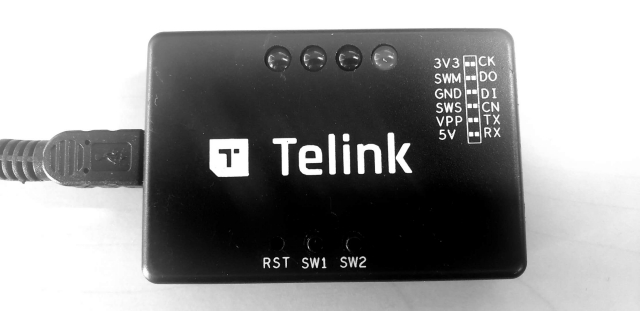
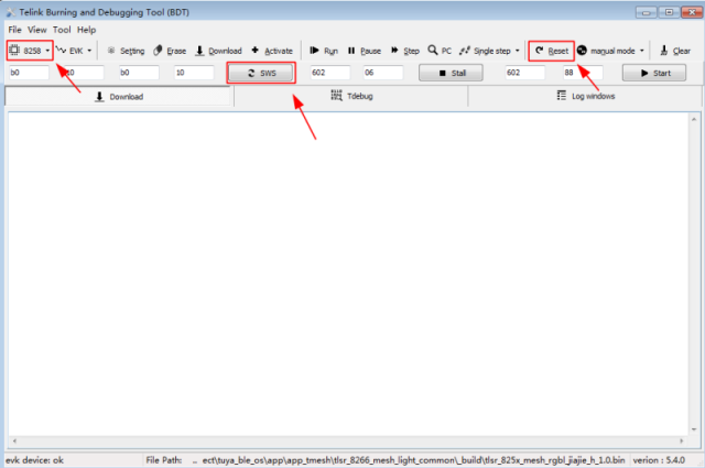
-
Open the Telink Burning and Debugging Tool (BTD), select 8258 chip, and click SWS to configure the writer.
This enables the writer to download code to 8258 chips. Typically, SWS is executed once.
-
Run
run.shto write thebinfile to your board.$ bash run.sh flash 5rgbcw_bt3l_pwm_V1.0.jsonNote:
run.shsupports build, flashing, flash after erasing all data, and cleaning build information.
Get the PID and license
All the devices must be authorized with the license before they can be connected to the Tuya Cloud. Contact the technical support and request the license.
Create a light product on the Tuya Developer Platform and get the PID. When you complete the steps below, the PID feature is completed. Otherwise, errors might occur.
-
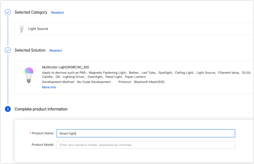
Log in to the Tuya Developer Platform and create a product. For more information, see Create Products.
For example, select the Light Source and Multicolor Light (Bluetooth) and complete the product information.
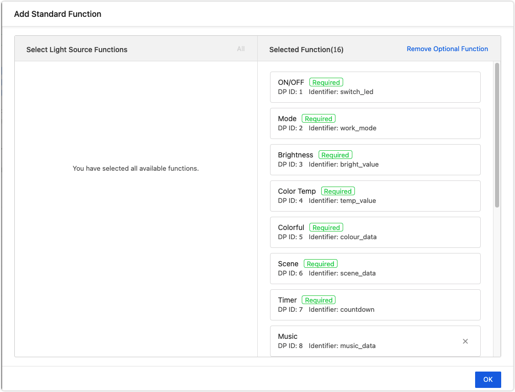
-
Add the functions and select a control panel.
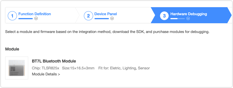
-
In the Hardware Debugging, choose the network modules.
-
So far, the product configuration is completed.
Is this page helpful?
YesFeedbackIs this page helpful?
YesFeedback


