4.x SDK Development Guide
This topic describes how to run the IPC SDK demo and develop a fully functional IPC product by using the IPC SDK. Each section describes how to integrate with a specific feature. You can implement functionality as needed.
Terms
| Term | Description |
|---|---|
| Pairing | A device can connect to the cloud through pairing with the mobile app. Pairing enables communications between the device, mobile app, and Tuya IoT. |
| Product ID | Product ID (PID) is automatically generated for each product created on the Tuya Developer Platform to record product information in the cloud. PID associates with the data points defined for a product. IPC devices of the same product category share the same PID. |
| UUID | A universally unique identifier (UUID) is a unique number generated by various algorithms to identify hardware or software. |
| AuthKey | AuthKey is used to authorize devices registered on the Tuya IoT to access Tuya cloud services. |
| P2P ID | P2P ID stands for point-to-point ID. For SDK V3.0.0 and later, the P2P ID is automatically assigned by the Tuya IoT without manually setting. |
| Token | A token is an identification code generated by the Tuya IoT When users scan the QR code to pair a device. A token is valid for 10 minutes. |
| DP | A data point (DP) represents a feature defined for a product. The DP serves the communication between a device and the Tuya IoT. |
| Chromecast | Google Chromecast is a streaming media adapter and can stream content from multiple platforms to your digital TV. |
| Echo Show | Amazon Echo Show is a smart speaker enabled with touchscreen and supports live streaming services. |
| IFTTT | IFTTT stands for If This Then That. It is a service that lets users connect to cloud services and smart devices to create automated actions. |
| OTA | OTA stands for over-the-air and refers to any type of wireless transmission. It is most commonly used to describe the wireless delivery of new software, firmware, or other data to mobile devices. |
SDK directory
The following directory shows what is included in the SDK.
.
└── tuya_ipc_sdk
	├── include
	│   ├── base_hwl.h
	│   ├── cJSON.h
	│   ├── tuya_cloud_base_defs.h
	│   ├── tuya_cloud_com_defs.h
	│   ├── tuya_cloud_error_code.h
	│   ├── tuya_cloud_types.h
	│   ├── tuya_cloud_wifi_defs.h
	│   ├── tuya_g711_utils.h
	│   ├── tuya_iot_config.h
	│   ├── tuya_ipc_ai_detect_storage.h
	│   ├── tuya_ipc_ai_face_db.h
	│   ├── tuya_ipc_ai_face_detect.h
	│   ├── tuya_ipc_api.h
	│   ├── tuya_ipc_chromecast.h
	│   ├── tuya_ipc_cloud_storage.h
	│   ├── tuya_ipc_echo_show.h
	│   ├── tuya_ipc_img_defs.h
	│   ├── tuya_ipc_img_proc.h
	│   ├── tuya_ipc_media.h
	│   ├── tuya_ipc_mqt_proccess.h
	│   ├── tuya_ipc_p2p.h
	│   ├── tuya_ipc_ptz.h
	│   ├── tuya_ipc_qrcode_proc.h
	│   ├── tuya_ipc_skill.h
	│   ├── tuya_ipc_stream_storage.h
	│   ├── tuya_ipc_video_msg.h
	│   ├── tuya_ipc_video_proc.h
	│   ├── tuya_ipc_webrtc.h
	│   ├── tuya_ipc_wifi_migrate.h
	│   ├── tuya_ring_buffer.h
	│   ├── uni_network.h
	│   └── wifi_hwl.h
	└── libs
		├── libmbedtls.a
		└── libtuya_ipc.a
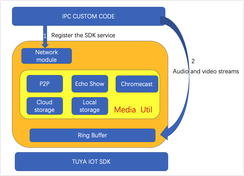
Integration processes
To develop with the IPC SDK, you need to first register the SDK service. The network module establishes a connection to the cloud. Then, you can feed the media in the required format into the buffer that is allocated by the SDK. At this point, the registration is completed and the SDK will take care of the subsequent services.
Users can control devices with a mobile app. With the raw media data, the SDK works with the mobile app to implement data storage, P2P networking, and third-party integration such as with Amazon Echo Show and Google Chromecast.
Get started
Walk through the following steps to get started with IPC SDK.
- Log in to the Tuya Developer Platform and create a product.
- Get Tuya’s IPC SDK.
- Download the SmartLife app from Apple Store or mobile app stores.
- Install Ubuntu Linux and set up the IDE.
- Run the demo on Ubuntu and try device functionality with the SmartLife app.
Step 1: Create product
For more information about the detailed processes of product creation, see Create Products.
-
Log in to the Tuya Developer Platform.
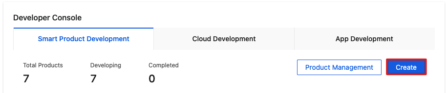
-
Click Create.
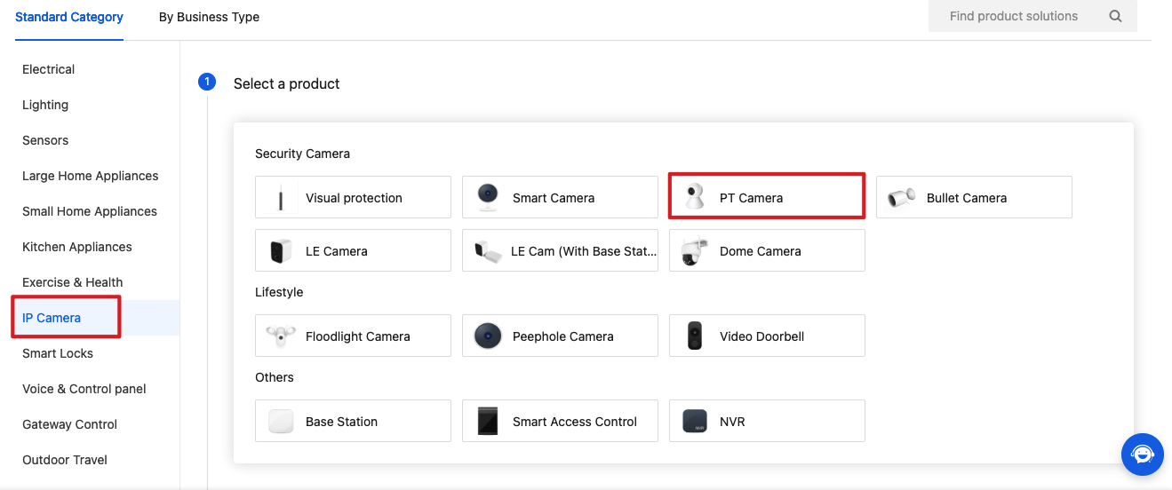
-
Choose IP Camera > PT Camera.
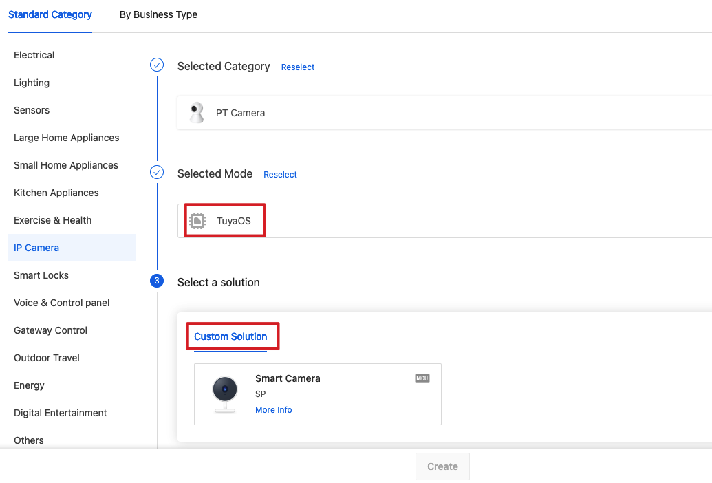
-
Choose TuyaOS for Smart Mode and choose Custom Solution.
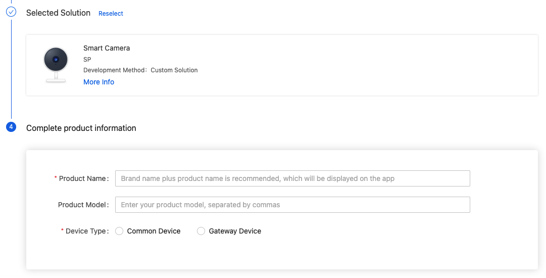
-
Complete the required information, such as product name and product model. Choose a Device Type. Click Create.
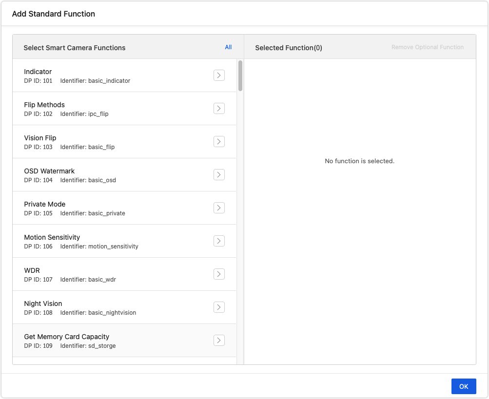
-
Select the standard function as needed.
-
Click Device Interaction.
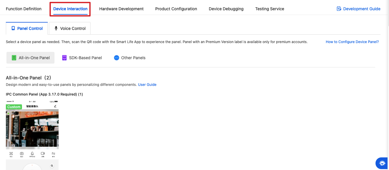
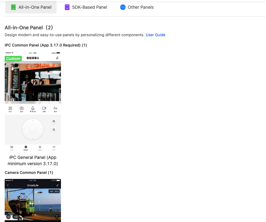
-
Scroll down the page and select a panel.
-
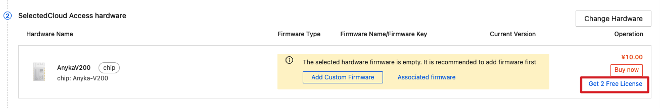
Click Hardware Development. Choose TuyaOS and select hardware.
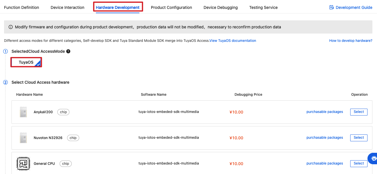
-
Click Get 2 Free Licenses to get the license for authorizing a device to connect to the Tuya Developer Platform.
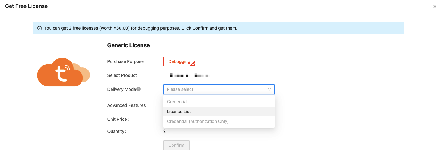
-
Choose a Delivery Mode.
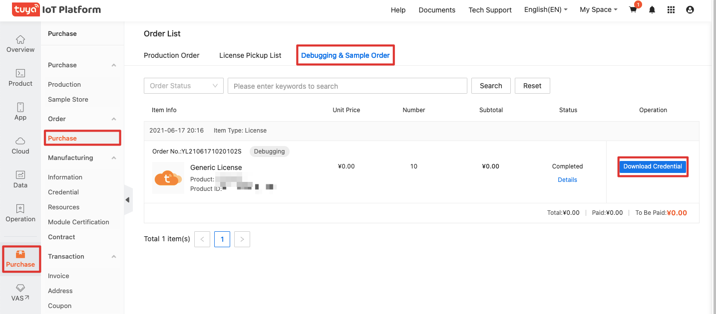
-
From the left navigation pane, choose Purchase > Debugging & Sample Order. Click Download Credential.
Now, you have created a product and got 2 licenses.
Step 2: Get IPC SDK
Log in to GitHub and download IPC SDK.
Step 3: Run the demo
Run the demo and try the IPC functionality on the SmartLife app.
-
Refer to the README file and download the sample code to your local computer.
#git clone https://github.com/tuya/tuya-iotos-embeded-multimedia-demo.git -
Extract the SDK to
demo_for_ipc/sdkand get the executable.#cd demo_for_ipc #make APP_NAME=demo -
Install the SmartLife app on your mobile phone. Open the app and tap the
+icon in the top right corner. Tap Security & Video Surveillance and select Smart Camera. Follow the steps to get a QR code. Scan this code to get the token.The token looks like this
{"s":"Tuya-Test","p":"88888888","t":"AYm1YVV5jupJcF"}and is valid for 10 minutes. -
Run the virtual machine and try the demo.
#cd output
#./tuya_ipc_demo -m 2 -p [PID] -u [UUID] -a [AUTHKEY] -r "[./]" -t "[TOKEN]"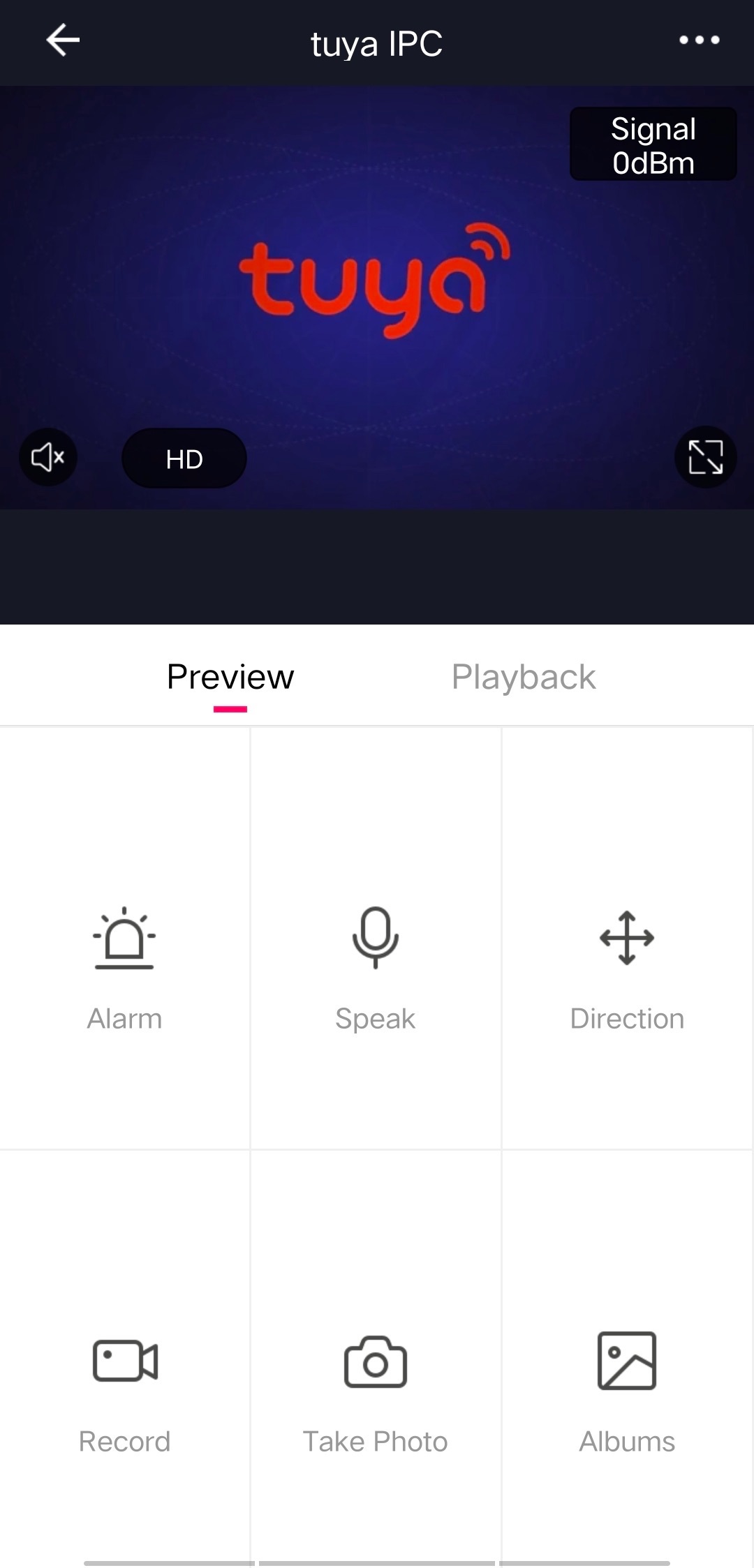
-
Experience various features by running different commands. For example, you can run the command below, and then you will receive a notification of motion detection in the message center.
#start
The table below lists commands for simulated operations.
Command Description start Trigger a motion detection event. stop Stop a motion detection event. status Get the device’s activation status. bell Trigger doorbell alerts.
Device pairing
The IPC SDK provides complete framework functions for implementing device pairing guides. This section describes the pairing processes and the purpose of each framework function. You can follow the description of each function and implement specific features accordingly.
Set basic parameters
-
Change the save paths of the DB file, OTA file, and local media file, with the following macros.
#define IPC_APP_STORAGE_PATH "/tmp/" #define IPC_APP_UPGRADE_FILE "/tmp/upgrade.file" #define IPC_APP_SD_BASE_PATH "/tmp/"Note: The DB file saves the device pairing information and must be physically stored on the computer so that the data won’t be lost if the power is turned off. Make sure to check whether or not there’s a slash (
/) at the end of the path to save the DB file and local media file. -
Change the macros for PID, UUID, and AuthKey:
Note: Contact Tuya’s project manager to get the PID. You can request the UUID and AuthKey after creating a product (PID) on the Tuya Developer Platform.
-
Change the macro for embedded software version:
#define IPC_APP_VERSION "1.2.3"Note: The version number must be set in the format
xx.xx.xx, no more than 20 characters.
Device paring in EZ mode (Wi-Fi Easy Connect)
-
In
IPC_APP_Init_SDK, selectWIFI_INIT_AUTOmode. Set thetokenparameter asNULL. -
The SDK goes to
hwl_wf_wk_mode_get.Note: You can implement this function as required to get the Wi-Fi module status.
OPERATE_RET hwl_wf_wk_mode_get(OUT WF_WK_MD_E *mode) { if(NULL == mode) { return OPRT_INVALID_PARM; } -
The SDK goes to the channel scanning
hwl_wf_all_ap_scan. The result of Wi-Fi channel scanning is passed into the structAP_IF_S.Note: You can implement this function as required to scan the Wi-Fi channel.
OPERATE_RET hwl_wf_all_ap_scan(OUT AP_IF_S **ap_ary,OUT UINT_T *num) { if(NULL == ap_ary || NULL == num) { return OPRT_INVALID_PARM; } static AP_IF_S s_aps[MAX_AP_SEARCH]; memset(s_aps, 0, sizeof(s_aps)); *ap_ary = s_aps; *num = 0; -
The SDK goes to
hwl_wf_sniffer_setthat the air interface packet received by the Wi-Fi module is passed into.Note: You can implement this function as required to get the sniffer status.
#define MAX_REV_BUFFER 512 BYTE_T rev_buffer[MAX_REV_BUFFER]; int skipLen = 26;/* Radiotap default length is 26 */ while((s_pSnifferCall != NULL) && (TRUE == s_enable_sniffer)) { int rev_num = recvfrom(sock, rev_buffer, MAX_REV_BUFFER, 0, NULL, NULL); ieee80211_radiotap_header *pHeader = (ieee80211_radiotap_header *)rev_buffer; skipLen = pHeader->it_len; -
If the SDK determines that air interface data is correct, it calls
hwl_wf_wk_mode_setto set the Wi-Fi status to station mode.Note: You can implement this function as required to enable different Wi-Fi modes.
case WWM_SNIFFER: { #ifndef WIFI_CHIP_7601 snprintf(tmpCmd, 100, "ifconfig %s down", WLAN_DEV); exec_cmd(tmpCmd); #endif snprintf(tmpCmd, 100, "iwconfig %s mode Monitor", WLAN_DEV); exec_cmd(tmpCmd); #ifndef WIFI_CHIP_7601 snprintf(tmpCmd, 100, "ifconfig %s up", WLAN_DEV); exec_cmd(tmpCmd); -
The SDK goes to
hwl_wf_station_connectto connect to the network.Note: You can implement this function as required to enable network connection.
OPERATE_RET hwl_wf_station_connect(IN CONST CHAR_T *ssid,IN CONST CHAR_T passwd) { if(sniffer_set_done) { sniffer_set_done = FALSE; IPC_APP_Notify_LED_Sound_Status_CB(IPC_REV_WIFI_CFG); usleep(10001000); } IPC_APP_Notify_LED_Sound_Status_CB(IPC_CONNECTING_WIFI); //TO DO //Add a blocking operation for the Wi-Fi connection here. sleep(2); return OPRT_OK; } -
After successful pairing, call
hwl_wf_station_stat_getto notify the SDK that the IP address is obtained.Note: This is a high-frequency API, so the API must return data in real time.
OPERATE_RET hwl_wf_station_stat_get(OUT WF_STATION_STAT_E *stat)
{
 if(NULL == stat)
 {
  return OPRT_INVALID_PARM;
 }
 *stat = WSS_GOT_IP; //Be sure to return in real time
 //Reserved
 return OPRT_OK;
}
Device paring in QR code mode
-
In
IPC_APP_Init_SDK, selectWIFI_INIT_AUTOmode. Set thetokenparameter asNULL. -
The SDK goes to
hwl_wf_wk_mode_get.Note: You can implement this function as required to get the Wi-Fi module status.
OPERATE_RET hwl_wf_wk_mode_get(OUT WF_WK_MD_E *mode) { if(NULL == mode) { return OPRT_INVALID_PARM; } -
The SDK goes to
hwl_wf_sniffer_setto get the result of QR code scanning.Note: To implement QR code recognition, you can call the ZBar library in
__tuya_linux_get_snap_qrcode.#define MAX_REV_BUFFER 512 BYTE_T rev_buffer[MAX_REV_BUFFER]; int skipLen = 26;/* Radiotap default length is 26 */ while((s_pSnifferCall != NULL) && (TRUE == s_enable_sniffer)) { int rev_num = recvfrom(sock, rev_buffer, MAX_REV_BUFFER, 0, NULL, NULL); ieee80211_radiotap_header *pHeader = (ieee80211_radiotap_header *)rev_buffer; skipLen = pHeader->it_len; -
If the SDK determines that QR code scanning succeeds, it calls
hwl_wf_wk_mode_setto set the Wi-Fi status to station mode.Note: You can implement this function as required to enable different Wi-Fi modes.
case WWM_SNIFFER: { #ifndef WIFI_CHIP_7601 snprintf(tmpCmd, 100, "ifconfig %s down", WLAN_DEV); exec_cmd(tmpCmd); #endif snprintf(tmpCmd, 100, "iwconfig %s mode Monitor", WLAN_DEV); exec_cmd(tmpCmd); #ifndef WIFI_CHIP_7601 snprintf(tmpCmd, 100, "ifconfig %s up", WLAN_DEV); exec_cmd(tmpCmd); -
The SDK goes to
hwl_wf_station_connectto connect to the network.Note: You can implement this function as required to enable network connection.
OPERATE_RET hwl_wf_station_connect(IN CONST CHAR_T *ssid,IN CONST CHAR_T passwd) { if(sniffer_set_done) { sniffer_set_done = FALSE; IPC_APP_Notify_LED_Sound_Status_CB(IPC_REV_WIFI_CFG); usleep(10001000); } IPC_APP_Notify_LED_Sound_Status_CB(IPC_CONNECTING_WIFI); //TO DO //Add a blocking operation for the Wi-Fi connection here. sleep(2); return OPRT_OK; } -
After successful pairing, call
hwl_wf_station_stat_getto notify the SDK that the IP address is obtained.Note: This is a high-frequency API, so the API must return data in real time.
OPERATE_RET hwl_wf_station_stat_get(OUT WF_STATION_STAT_E *stat)
{
 if(NULL == stat)
 {
  return OPRT_INVALID_PARM;
 }
 *stat = WSS_GOT_IP; //Be sure to return in real time
 //Reserved
 return OPRT_OK;
}
Device paring in access point (AP) mode
-
In
IPC_APP_Init_SDK, selectWIFI_INIT_APmode. Set thetokenparameter asNULL. -
The SDK goes to
hwl_wf_wk_mode_get.Note: You can implement this function as required to get the Wi-Fi module status.
OPERATE_RET hwl_wf_wk_mode_get(OUT WF_WK_MD_E *mode) { if(NULL == mode) { return OPRT_INVALID_PARM; } -
The SDK goes to
hwl_wf_ap_startto enable AP mode.Note: Enable AP mode according to the parameters of the struct
WF_AP_CFG_IF_S.OPERATE_RET hwl_wf_ap_start(IN CONST WF_AP_CFG_IF_S *cfg) { if(NULL == cfg) { return OPRT_INVALID_PARM; } printf("Start AP SSID:%s \r\n", cfg->ssid); //Reserved return OPRT_OK; } -
If the SDK receives the pairing information for AP mode, it calls
hwl_wf_wk_mode_setto set the Wi-Fi status to station mode.Note: You can implement this function as required to enable different Wi-Fi modes.
case WWM_STATION: { #ifndef WIFI_CHIP_7601 snprintf(tmpCmd, 100, "ifconfig %s down", WLAN_DEV); exec_cmd(tmpCmd); #endif snprintf(tmpCmd, 100, "iwconfig %s mode Managed", WLAN_DEV); exec_cmd(tmpCmd); #ifndef WIFI_CHIP_7601 snprintf(tmpCmd, 100, "ifconfig %s up", WLAN_DEV); exec_cmd(tmpCmd); #endif -
The SDK goes to
hwl_wf_station_connectto connect to the network.Note: You can implement this function as required to enable network connection.
OPERATE_RET hwl_wf_station_connect(IN CONST CHAR_T *ssid,IN CONST CHAR_T passwd) { if(sniffer_set_done) { sniffer_set_done = FALSE; IPC_APP_Notify_LED_Sound_Status_CB(IPC_REV_WIFI_CFG); usleep(10001000); } IPC_APP_Notify_LED_Sound_Status_CB(IPC_CONNECTING_WIFI); //TO DO //Add a blocking operation for the Wi-Fi connection here. sleep(2); return OPRT_OK; } -
After successful pairing, call
hwl_wf_station_stat_getto notify the SDK that the IP address is obtained.Note: This is a high-frequency API, so the API must return data in real time.
OPERATE_RET hwl_wf_station_stat_get(OUT WF_STATION_STAT_E *stat)
{
 if(NULL == stat)
 {
  return OPRT_INVALID_PARM;
 }
 *stat = WSS_GOT_IP; // Be sure to return in real time
 // Reserved
 return OPRT_OK;
}
Device pairing in wired mode (scan devices in LAN)
-
The device calls
IPC_APP_Init_SDKfor SDK initialization. -
The SDK calls
hwl_wf_get_ipto get the IP address of the device. If the device detects that the router is connected, it returns the IP address.Note: You can implement this function as required to get the IP address.
OPERATE_RET hwl_wf_get_ip(IN CONST WF_IF_E wf,OUT NW_IP_S *ip) { if(NULL == ip) { return OPRT_INVALID_PARM; } -
The SDK goes to
hwl_wf_get_macto get the MAC address of the device.Note: You can implement this function as required to get the MAC address.
OPERATE_RET hwl_wf_get_mac(IN CONST WF_IF_E wf,INOUT NW_MAC_S *mac) { if(NULL == mac) { return OPRT_INVALID_PARM; } -
The SDK broadcasts the IP address and MAC address through the router. When the mobile phone connects to the Wi-Fi network and receives the broadcast, it will request a token from the server. Then, the mobile phone sends the token to the device for pairing.
Device pairing in wired mode (scan QR code)
-
Make sure you have downloaded the wired-supported IPC SDK and the UUID has been tagged in the background.
-
Call
IPC_APP_Init_SDKfor SDK initialization. SetWIFI_INIT_MODE_EasWIFI_INIT_NULLandtokenas NULL. -
The device calls
tuya_ipc_set_regionto set the country code of the device.Note: The country code must be set to the actual country/region where the device is distributed. Otherwise, exceptions might occur when the device communicates with the server.
#if defined(QRCODE_ACTIVE_MODE) && (QRCODE_ACTIVE_MODE==1) tuya_ipc_set_region(REGION_CN); p_token = NULL; #endif -
The device calls
tuya_ipc_get_qrcodeto get the URL of the QR code.Note: The URL of each UUID is permanent. For devices with screen, you can convert the URL to a QR code for display. For devices without screen, you can print a short URL and attach it to the packaging.
#if defined(QRCODE_ACTIVE_MODE) && (QRCODE_ACTIVE_MODE==1) /* demo: how to get QR code from Tuya server for display */ sleep(2); CHAR_T info[32] = {0}; tuya_ipc_get_qrcode(NULL,info, 32); printf("###info:%s\n", info); #endif -
Tap the scan icon in the top right corner of the app to scan the QR code for device activation.
Media-related features
Live preview
When the SDK is initialized, a 10-second media cache will be created by default. You can feed the media data into the ring buffer.
The SDK library already enables data transmission, so related development is not required.
Development processes
-
Confirm the video parameter in the
IPC_APP_Set_Media_Info.Note: We recommend that the size of the group of pictures (GOP) be set to two to three times the frame per second (FPS) and the resolution be 16:9. The bitrate cannot exceed 1.5 Mbit/s. H.264 and H.265 encoding formats are supported.
s_media_info.channel_enable[E_CHANNEL_VIDEO_MAIN] = TRUE; /* Whether to enable local HD video streaming / s_media_info.video_fps[E_CHANNEL_VIDEO_MAIN] = 30; / FPS / s_media_info.video_gop[E_CHANNEL_VIDEO_MAIN] = 30; / GOP / s_media_info.video_bitrate[E_CHANNEL_VIDEO_MAIN] = TUYA_VIDEO_BITRATE_1M; / Rate limit / s_media_info.video_width[E_CHANNEL_VIDEO_MAIN] = 640; / Single frame resolution of width*/ s_media_info.video_height[E_CHANNEL_VIDEO_MAIN] = 360;/* Single frame resolution of height / s_media_info.video_freq[E_CHANNEL_VIDEO_MAIN] = 90000; / Clock frequency / s_media_info.video_codec[E_CHANNEL_VIDEO_MAIN] = TUYA_CODEC_VIDEO_H264; / Encoding format */ -
Confirm the audio parameter in the
IPC_APP_Set_Media_Info.Note: The audio format supports PCM, G.711u, and G.711a. The maximum upload size is 1,400 bytes. The audio sent from the app is fixed to 320 bytes. 8K and 16K audio are supported.
s_media_info.channel_enable[E_CHANNEL_VIDEO_SUB] = TRUE; /* Whether to enable local SD video stream / s_media_info.video_fps[E_CHANNEL_VIDEO_SUB] = 30; / FPS / s_media_info.video_gop[E_CHANNEL_VIDEO_SUB] = 30; / GOP / s_media_info.video_bitrate[E_CHANNEL_VIDEO_SUB] = TUYA_VIDEO_BITRATE_512K; / Rate limit / s_media_info.video_width[E_CHANNEL_VIDEO_SUB] = 640; / Single frame resolution of width / s_media_info.video_height[E_CHANNEL_VIDEO_SUB] = 360;/ Single frame resolution of height / s_media_info.video_freq[E_CHANNEL_VIDEO_SUB] = 90000; / Clock frequency / s_media_info.video_codec[E_CHANNEL_VIDEO_SUB] = TUYA_CODEC_VIDEO_H264; / Encoding format */ -
The media data collected by the camera is passed into the ring buffer through
tuya_ipc_ring_buffer_append_data./* append new frame into a ring buffer*/ OPERATE_RET tuya_ipc_ring_buffer_append_data(CHANNEL_E channel, UCHAR_T *addr, UINT_T size, MEDIA_FRAME_TYPE_E type, UINT64_T pts); -
TUYA_APP_Enable_Speaker_CBimplements speaker on/off switch.VOID TUYA_APP_Enable_Speaker_CB(BOOL_T enabled) { printf("enable speaker %d \r\n", enabled); //TO DO /* Developers need to turn on or off speaker hardware operations. If IPC hardware features do not need to be explicitly turned on, the function can be left blank. */ } -
TUYA_APP_Rev_Audio_CBimplements audio playback.VOID TUYA_APP_Rev_Audio_CB(IN CONST MEDIA_FRAME_S *p_audio_frame, TUYA_AUDIO_SAMPLE_E audio_sample, TUYA_AUDIO_DATABITS_E audio_databits, TUYA_AUDIO_CHANNEL_E audio_channel) { printf("rev audio cb len:%u sample:%d db:%d channel:%d\r\n", p_audio_frame->size, audio_sample, audio_databits, audio_channel); //PCM-Format 8K 16Bit MONO //TO DO /*Developers need to implement the operations of voice playback */ } -
The app sends the audio in G.711u format by default. If the device requires PCM audio, you can call
tuya_g711_decodeto transcode the audio.Description: Function parameters are as follows.
- 1: TUYA_G711_MU_LAW
- 2: The address of resolved data
- 3: The length of resolved data
- 4: The output address after data is resolved
- 5: The length after data is resolved
int tuya_g711_decode(unsigned char type, unsigned short *src, unsigned int srcLen, unsigned char *drc, unsigned int *pOut);
Local recording
The SDK library has integrated the local storage feature. You just need to feed the media data into the ring buffer to complete the local storage setting.
This section describes how to implement the local storage of video and related settings.
Time synchronization
-
After MQTT is connected, call
IPC_APP_Sync_Utc_Timeto synchronize the time with the server. Use the callback__IPC_APP_Get_Net_Status_cbto determine whether MQTT is connected.Description:
- Before you enable the local storage, you must synchronize the time with the server. Otherwise, users might not find videos to playback due to the incorrect time.
- Failures might occur during time synchronization. You can call the API several times before the operation succeeds.
STATIC VOID __IPC_APP_Get_Net_Status_cb(IN CONST BYTE_T stat) { PR_DEBUG("Net status change to:%d", stat); switch(stat) { #if defined(WIFI_GW) && (WIFI_GW == 1) case STAT_CLOUD_CONN: //For Wi-Fi IPC case STAT_MQTT_ONLINE: //For low-power Wi-Fi IPC #endif #if defined(WIFI_GW) && (WIFI_GW==0) case GB_STAT_CLOUD_CONN: //For wired IPC #endif { IPC_APP_Notify_LED_Sound_Status_CB(IPC_MQTT_ONLINE); PR_DEBUG("mqtt is online\r\n"); s_mqtt_status = 1; break; -
The device calls
IPC_APP_Sync_Utc_Timeto synchronize with the server time.Description:
- For the time zone setting, if a device has never been paired, you can change the time zone on the mobile phone before pairing this device. However, changing the time zone does not apply to an already paired device.
- The time zone on the mobile phone prevails, independent of the region of the account and the time zone displayed on the app.
OPERATE_RET IPC_APP_Sync_Utc_Time(VOID) { TIME_T time_utc; INT_T time_zone; PR_DEBUG("Get Server Time "); OPERATE_RET ret = tuya_ipc_get_service_time_force(&time_utc, &time_zone); if(ret != OPRT_OK) { return ret; } //The API returns OK, indicating that UTC time has been successfully obtained. //If it return not OK, the time has not been fetched. PR_DEBUG("Get Server Time Success: %lu %d", time_utc, time_zone); return OPRT_OK; } -
Call
tuya_ipc_check_in_dlsto determine whether daylight saving time (DST)is in effect. When DST is in effect, the time zone goes forward one hour.Note: Certain regions seasonally change their time zone offset by DST rules. Therefore, devices must determine whether DST is in effect at the specified time.
/* \fn OPERATE_RET tuya_ipc_check_in_dls(IN TIME_T time_utc, OUT BOOL * pIsDls) \brief Check if the specified UTC time is in daylight saving time \return OPERATE_RET */ OPERATE_RET tuya_ipc_check_in_dls(IN TIME_T time_utc, OUT BOOL_T * pIsDls); -
Sample code:
TIME_T time_utc;
tuya_ipc_get_utc_time(&time_utc);
BOOL_T isDls = FALSE;
tuya_ipc_check_in_dls(time_utc,&isDls);
if (TRUE == isDls)
{
 time_utc += 3600;
}
Local storage
-
Call
TUYA_APP_Init_Stream_Storageto initialize the local storage. The app sends the command to enable event recording or full-time recording.Description:
- After continuous storage is enabled, the SDK will automatically save the video to the SD card. When the device is started, local storage initialization only needs to be called once.
- Local storage only supports an SD card in FAT32 format. If the device detects an unsupported SD card, it will report this error to the server through a DP.
- When users tap the SD card setting on the app, they will get a format error message. The app will guide users to format the SD card.
OPERATE_RET TUYA_APP_Init_Stream_Storage(IN CONST CHAR_T *p_sd_base_path) { STATIC BOOL_T s_stream_storage_inited = FALSE; if(s_stream_storage_inited == TRUE) { PR_DEBUG("The Stream Storage Is Already Inited"); return OPRT_OK; } -
If event storage is enabled, when the device needs to record, it calls
tuya_ipc_ss_start_eventto start recording andtuya_ipc_ss_stop_eventto stop recording. The maximum time to record a single event is 10 minutes. If the device does not calltuya_ipc_ss_stop_eventfor more than 10 minutes, the SDK will automatically stop recording. -
You can implement SD card detection in
tuya_ipc_sd_get_statusas needed.Note: When the device detects unsupported SD cards such as SD cards in NTFS format,
abnormalwill be returned. Otherwise,normalwill be returned.E_SD_STATUS tuya_ipc_sd_get_status(VOID) { FILE *fp = fopen(LINUX_SD_DEV_FILE, "rb"); if(!fp) { return SD_STATUS_NOT_EXIST; } fclose(fp);
Data points (DPs)
DPs are used to control different features of a device. You need to set DPs for the device and report the DP status to the server after setting. The tuya_ipc_utils.h file specifies the common DPs. You can implement DPs based on the sample code. You can also add and set custom DPs by referring to the existing DP code of the same data type.
Save and read DP data
-
__tuya_app_write_INTand__tuya_app_write_STRimplement DP data storage.STATIC VOID __tuya_app_write_INT(CHAR_T *key, INT_T value) { //TO DO CHAR_T tmp_cmd[128] = {0}; snprintf(tmp_cmd, 128, "mkdir -p /tmp/tuya.cfgs/;echo %d > /tmp/tuya.cfgs/%s", value, key); printf("write int exc: %s \r\n", tmp_cmd); system(tmp_cmd); } STATIC VOID __tuya_app_write_STR(CHAR_T *key, CHAR_T *value) { //TO DO CHAR_T tmp_cmd[256] = {0}; snprintf(tmp_cmd, 256, "echo %s > /tmp/tuya.cfgs/%s", value, key); printf("write STR exc: %s \r\n", tmp_cmd); system(tmp_cmd); } -
__tuya_app_read_INTand__tuya_app_read_STRimplement DP data reading.STATIC INT_T __tuya_app_read_INT(CHAR_T *key) { //TO DO CHAR_T tmp_file[64] = {0}; snprintf(tmp_file, 64, "cat /tmp/tuya.cfgs/%s", key); printf("read int exc: %s \r\n", tmp_file); FILE *p_file = popen(tmp_file, "r"); STATIC INT_T __tuya_app_read_STR(CHAR_T *key, CHAR_T *value, INT_T value_size) { //TO DO memset(value, 0, value_size); CHAR_T tmp_file[64] = {0}; snprintf(tmp_file, 64, "cat /tmp/tuya.cfgs/%s", key); printf("read str exc: %s \r\n", tmp_file); FILE *p_file = popen(tmp_file, "r");
On screen display (OSD) timestamp
- The DP ID of the OSD timestamp is DP 104.
- The DP value sent from the server enables the device to add a timestamp to the video or remove it from the video. On the device, you can set where to place a timestamp on the video.
Passive infrared (PIR)
- The DP ID of the PIR feature is DP 152.
- The DP value sent from the server can enable or disable the PIR feature and adjust the sensitivity. When the PIR is triggered, the device calls
tuya_ipc_notify_door_bell_pressto report the images captured by the camera to the server.Note: We recommend that the frequency of detection and data reporting should be greater than 30 seconds.
Motion detection
The SDK provides functions to implement motion detection on/off, sensitivity adjustment, timing, intermittent control, and data reporting. Besides, the library of SDK V4.4.6 has implemented motion detection and motion tracking. You can call the SDK API to implement these two features.
Motion detection (general)
-
The DP of motion detection on/off is DP 134. The DP of motion detection sensitivity is DP 106.
-
When motion detection is enabled, once the device detects a motion and captures images, it calls
tuya_ipc_notify_motion_detectto upload images to the server.Note: To report motion detection events, the image format must be selected.
/*
\fn OPERATE_RET tuya_ipc_notify_motion_detect
\brief send a motion-detection alarm to Tuya IoT and app
\param[in] snap_buffer: address of current snapshot
\param[in] snap_size: size fo snapshot, in Byte
\param[in] type: snapshot file type, jpeg or png
\return OPERATE_RET
*/
OPERATE_RET tuya_ipc_notify_motion_detect(IN CONST CHAR_T *snap_buffer, IN CONST UINT_T snap_size, IN CONST NOTIFICATION_CONTENT_TYPE_E type);
Motion detection (SDK integration)
-
Call
Tuya_Ipc_Motion_Initto initialize motion detection./********************************************************************************* * Init input config. **********************************************************************************/ OPERATE_RET Tuya_Ipc_Motion_Init(TUYA_MOTION_TRACKING_CFG mt_cfg); -
The following describes the initialization parameters of the struct
TUYA_MOTION_TRACKING_CFG.typedef struct _TUYA_MOTION_TRACKING_CFG { INT_T frame_w; // The width of the video frame. INT_T frame_h; // The height of the video frame. INT_T y_thd; // The threshold of motion detection, which defaults to 30. You can set a threshold from 0 to 1255. The recommended value is 540. Smaller values will trigger motion detection more easily. INT_T sensitivity; // Motion detection sensitivity. The value is from 1 to 7. The larger the value, the more sensitive the device. TUYA_RPERCENT_ECT roi; // Select a region of interest (ROI). To set this value, see the struct TUYA_RECT. INT_T tracking_enable; // Motion tracking on/off. If you want to only enable motion detection, set this value to 0. To enable motion tracking, set it to 1. }TUYA_MOTION_TRACKING_CFG; -
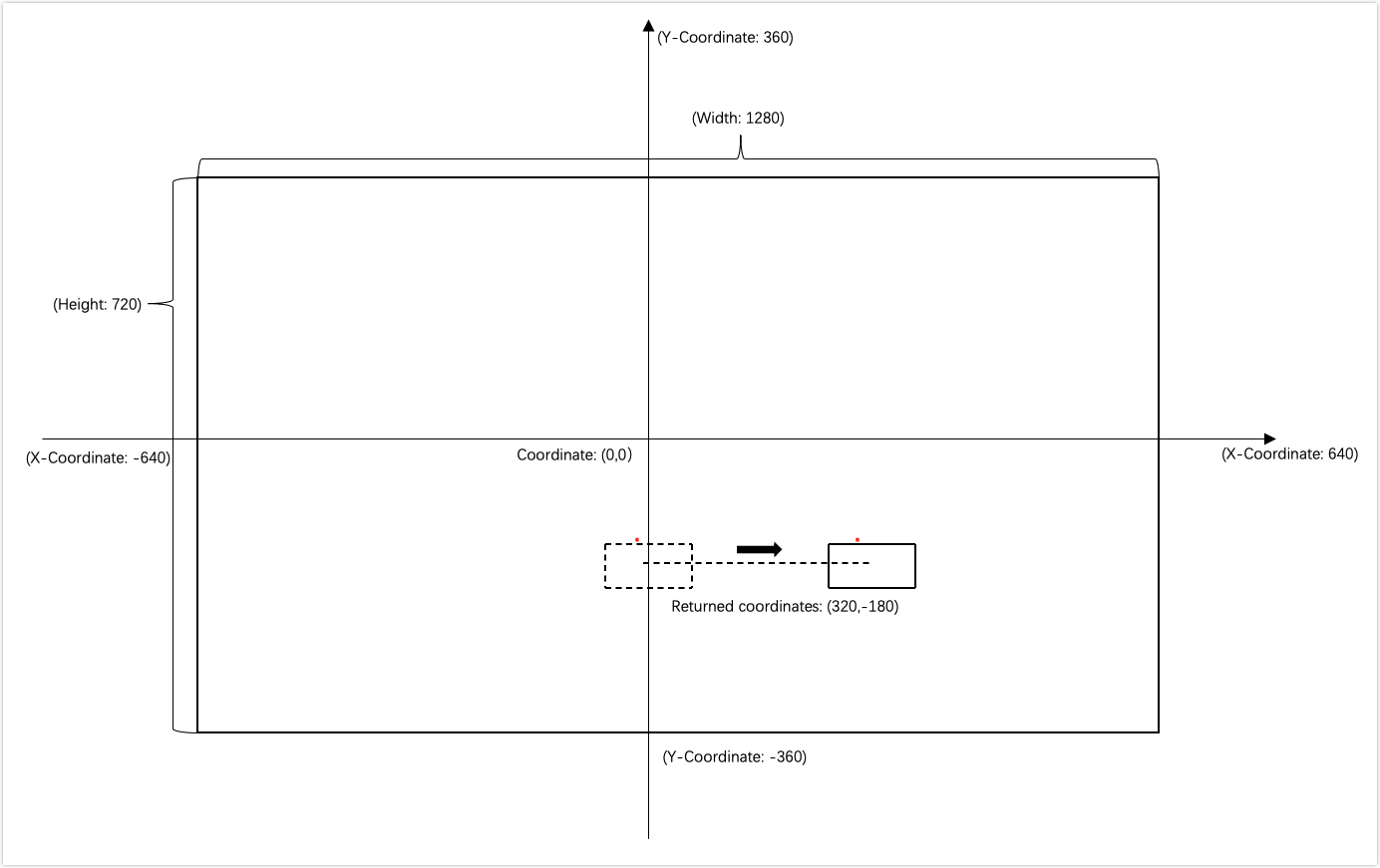
The following describes the initialization parameters of the struct
TUYA_RECT.typedef struct _TUYA_RECT { INT_T left; // The percentage of the x-coordinate to the width of a video frame in the region coordinate. The value must be rounded. For example, if the x-coordinate is 128, the percentage value is 10%. INT_T top; // The percentage of the y-coordinate to the height of a video frame in the region coordinate. The value must be rounded. For example, if the x-coordinate is 72, the percentage value is 10%. INT_T right; // The percentage of the width of the selected ROI to the width of a video frame in the region coordinate. The value must be rounded. For example, if the width of the selected ROI is 256, the percentage value is 20%. INT_T bottom; // The percentage of the height of the selected ROI to the height of a video frame in the region coordinate. The value must be rounded. For example, if the width of the selected ROI is 144, the percentage value is 20%. }TUYA_AI_RECT; -
The following figure shows how the struct
TUYA_RECTworks.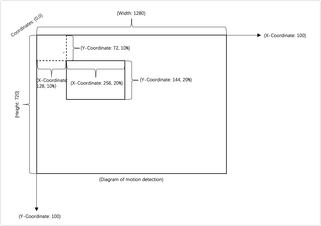
-
After the initialization function
Tuya_Ipc_Motion_Initis called, to modify the parameters of motion detection, callTuya_Ipc_Set_Motion./********************************************************************************* * Set config dynamically. **********************************************************************************/ OPERATE_RET Tuya_Ipc_Set_Motion(TUYA_MOTION_TRACKING_CFG mt_cfg); -
Tuya_Ipc_Get_Motioncan get the parameters of motion detection./********************************************************************************* * Get config dynamically. **********************************************************************************/ void Tuya_Ipc_Get_Motion(TUYA_MOTION_TRACKING_CFG *mt_cfg); -
The device calls the
Tuya_Ipc_Motionat regular intervals to pass in the collected YUV data. If the SDK tells the difference between two images and triggers an alert,1is returned. Otherwise,0is returned.Description:
- The image must be in
YUV420format. You can fine-tune values for motion tracking. We recommend that you use the average results of five motion tracking actions as the rotation angle of the servo. This can minimize the occurrence of missed tracking. - The frequency of calling
Tuya_Ipc_Motiondepends on the fine-tuned values for motion tracking. The following describes the parameters ofTuya_Ipc_Motion:in_data: The input images in YUV420 format.motion_flag: If it returns1, motion detection is triggered.motion_point: When motion tracking is enabled, the function returns x and y coordinates of the current position of the moving object.
/********************************************************************************* * Execute Motion Detect \ Motion Tracking. * in_data Input YUV. * motion_flag Return the value of Motion Detect. 0 for no moving; 1 for moving exist. * motion_point Return the center point coordinate of the largest moving object. Both values(x, y) are 0 for no moving; otherwise, moving exist. Return values(0, 0) when tracking_enable==0 **********************************************************************************/ OPERATE_RET Tuya_Ipc_Motion(UCHAR_T *in_data, INT_T *motion_flag, TUYA_POINT * motion_point); - The image must be in
-
If
Tuya_Ipc_Motiontells the difference between two images and triggers motion tracking, it returns x and y coordinates of the current position of the moving object. See the following legend.Note: The device calculates the rotation angle of the servo based on the returned coordinates and controls the servo to move to the decided angle.
-
During the OTA update, to release memory, call
Tuya_Ipc_Motion_Releaseto exit motion detection and motion tracking./********************************************************************************* * release. **********************************************************************************/ void Tuya_Ipc_Motion_Release();
Motion detection interval
- The DP ID of motion detection interval is DP 133.
- The DP value sent from the server can enable motion detection at a specified interval. If the DP value is 5, motion detection is enabled at five-minute intervals and executed for five minutes each time.
Image scaling (SDK integration)
Image scaling refers to the resizing of captured images to fit the required resolution.
Development processes
-
Call
Tuya_Ipc_Img_Resizeto pass in the image, parameter, and image output address.Description: The following describes the parameters of
Tuya_Ipc_Img_Resize:in_data: The address of the input image. The image must be in YUV420 format.paras: The parameter of the input image.out_data: The image output address.
/********************************************************************************* * YUV420 image scale interface * in_data input YUV420 * paras scale struct * out_data output YUV420 **********************************************************************************/ OPERATE_RET Tuya_Ipc_Img_Resize(UCHAR_T *in_data, TUYA_IMG_RESIZE_PARA paras, UCHAR_T *out_data); -
The following describes the parameters of the struct
TUYA_IMG_RESIZE_PARA:typedef struct _TUYA_IMG_RESIZE_PARA { INT_T srcWidth; // The width of the input image. INT_T srcHeight; // The height of the input image. INT_T dstWidth; // The width of the output image. INT_T dstHeight; // The height of the output image. IMG_TYPE img_type; // The scaling type. IMG_RESIZE_TYPE resize_type; }TUYA_IMG_RESIZE_PARA; -
The following describes the parameters of the encrypted struct
IMG_RESIZE_TYPE:typedef enum { LINEAR, // The scaling process is quick, but the image quality is poor. CUBIC, // The scaling process is slow, but the image quality is high. }IMG_RESIZE_TYPE;
Features of PTZ cameras
The device receives the command from the server and then controls the PTZ camera to rotate to the specified angle.
General features
- The device receives specified DP values from the server and then controls the camera to rotate to the specified angle. For example, the device starts rotating with DP 119 and stops rotating with DP 116. The table below lists the DPs for general controls.
| DP ID | Description |
|---|---|
| 119 | The pan-tilt motor rotates the camera. 0: upper right 1: right 2: lower right 3: down 4: lower left 5: left 6: upper left 7: up |
| 116 | The pan-tilt motor stops rotating the camera. This DP is of the boolean type. |
| 161 | Enable or disable motion tracking. This DP is of the boolean type. true: enable false: disable |
| 178 | Add or delete preset points. This DP is of the string type. The string differs depending on operation types. type 1: add type 2: delete |
Preset points
-
The DP of preset points.
#define TUYA_DP_PRESET_SET 178 /* Add or delete preset points. This DP is of the string type. The string differs depending on operation types. `type 1`: add. `type 2`: delete. */ -
To add a preset point, the device must report the non-cruise status of DP 179.
-
When the device receives DP data from the server, it adds the function
tuya_ipc_preset_add.error_num = tuya_ipc_preset_add(&node[num]); snprintf(respond_add,128,"{\"type\":%d,\"data\":{\"seq\":%d,\"pan\":%d,\"tilt\": %d,\"zoom\": 0 }}", type-valueint,error_num,node[num].ptz.pan,node[num].ptz.tilt); -
Struct
S_PRESET_POSITIONDescription:
id[32]: The ID value from the server, which can be ignored.name[32]: The name of an added preset point, which can be stored.[]mpId: Specify a serial number for an added preset point, starting with one.ptz: Specify the pan and tilt coordinates of an added preset point. For fixed-focus cameras, set the coordinate of zoom to 0.
typedef struct { CHAR_T id[32]; //id in server CHAR_T name[32]; //preset point name INT_T mpId; //index ID S_PRESET_PTZ ptz; //ptz for preset position } S_PRESET_POSITION; typedef struct { INT_T pan; // The pan coordinate. That is, the horizontal value in a pair of coordinates. INT_T tilt; // The tilt coordinate. That is, the vertical value in a pair of coordinates. INT_T zoom; // For fixed-focus cameras, set this value to 0. }S_PRESET_PTZ; -
Call
tuya_ipc_preset_add_picto pass in the address and size of an image./* \fn OPERATE_RET tuya_ipc_preset_add_pic(CHAR_T *addr, UINT_T size) \brief upload a snapshot for current preset position \param[in] addr/size: address and size of the picture to be uploaded \return OPERATE_RET */ OPERATE_RET tuya_ipc_preset_add_pic(CHAR_T *addr, UINT_T size); -
After the device is powered on, call
tuya_ipc_preset_getto synchronize the existing preset points with the server./* \fn OPERATE_RET tuya_ipc_preset_get(S_PRESET_CFG *preset_cfg) \brief get all preset positions stored in tuya cloud. \param[in out] preset_cfg \return OPERATE_RET */ OPERATE_RET tuya_ipc_preset_get(S_PRESET_CFG *preset_cfg); -
The server sends a command to delete a preset point. After executing the command, the device calls
tuya_ipc_preset_delto return the ID contained in the command.// Delete preset points. The error alternates between 0 and 1. if(tmp == 0) { tmp = 1; } else if(tmp == 1) { tmp = 0; } tuya_ipc_preset_del(devId->valuestring); snprintf(respond_del,128,"{"type":%d,"data":{"error":%d}}",type->valueint,tmp);
Access point (AP) preview
Enable AP preview
-
Create four custom DPs: DP 231, DP 232, DP 233, and DP 234.
-
Enter AP information on the app, including the SSID and password. Send the information to the device through DP 232. That is, trigger
handle_DP_AP_SWITCH.STATIC VOID handle_DP_AP_SWITCH(IN TY_OBJ_DP_S *p_dp_json) { CHAR_T resp[32] = {0}; INT_T ap_enable = IPC_APP_set_ap_mode((cJSON *)p_dp_json->value.dp_str); if(ap_enable < 0) { snprintf(resp, 32, "{"ap_enable":0,"errcode":0}"); } else { snprintf(resp, 32, "{"ap_enable":%d,"errcode":0}",ap_enable); } respone_dp_str(TUYA_DP_AP_SWITCH, resp); if(ap_enable >= 0) { change_ap_process(); } } -
IPC_APP_set_ap_modecontains AP information. The device callstuya_ipc_save_ap_infoto save the SSID and password of the AP to the Tuya database. The device responds to DP 232 with"{"ap_enable":1,"errcode":0}"and responds to DP 231 with"{"is_ap":1,"ap_ssid":"xxx","password":"xxx"}".Note: After the device responds to DP 232, it needs to send the status of DP 231 to synchronize the device status with the server.
INT_T IPC_APP_set_ap_mode(IN cJSON *p_ap_info) { if (NULL == p_ap_info) { return 0; } INT_T ap_onoff = -1; printf("%s %d handle_DP_AP_SWITCH:%s rn",FUNCTION,LINE, (char *)p_ap_info); cJSON * pJson = cJSON_Parse((CHAR_T *)p_ap_info); -
After the DP is reported, the Wi-Fi status is switched from station mode to AP mode. The mobile phone will connect to the corresponding AP. Tap the device list for AP preview.
-
If the device has enabled AP mode, unplug and restart the device. Set parameters for SDK initialization function
IPC_APP_Init_SDK. SetWIFI_INIT_MODE_EasWIFI_INIT_APandtokenasNULL. Calltuya_ipc_set_ap_infoto pass in AP information.Note: After the device is unplugged and restarted, the device cannot connect to the internet in AP preview. The P2P initialization must be independent of the MQTT connection. That is, P2P initialization starts after the SDK initialization is completed.
/*
\fn OPERATE_RET tuya_ipc_set_ap_info(IN CONST CHAR_T *ssid, IN CONST CHAR_T *passwd)
\brief set ap info when start SDK
\return OPERATE_RET
*/
OPERATE_RET tuya_ipc_set_ap_info(IN CONST CHAR_T *ssid, IN CONST CHAR_T *passwd);
Get system time
After the device is connected to the app, the app sends UTC time through DP 233 and time zone through DP 234. The device calls tuya_ipc_set_service_time and uni_set_time_zone to write UTC time and time zone into the SDK.
Note: The time zone is set in the format
+/-hh:mm, such as-05:00for New York that does not observe DST.
/*
\fn OPERATE_RET tuya_ipc_set_service_time(IN TIME_T new_time_utc)
\brief set time of tuya SDK
\return OPERATE_RET
*/
OPERATE_RET tuya_ipc_set_service_time(IN TIME_T new_time_utc);

/*
\Function: uni_set_time_zone
\Input: time_zone->"+/-hh:mm"
\Output: none
\ Return: none
*/
OPERATE_RET uni_set_time_zone(IN CONST CHAR_T *time_zone)
Disable AP preview
-
Tap Stop AP mode on the app.
handle_DP_AP_SWITCHis triggered to disable Wi-Fi AP mode. Then,tuya_ipc_reconnect_wifiis triggered and the device is connected to Wi-Fi.if(cur_mode == WWM_SOFTAP) { hwl_wf_ap_stop(); tuya_ipc_reconnect_wifi(); } -
If the device has disabled AP mode, unplug and restart the device. Set parameters for SDK initialization function
IPC_APP_Init_SDK. LeaveWIFI_INIT_MODE_Eas is and settokenasNULL. Calltuya_ipc_set_ap_infoto pass in AP information.Note: If AP preview is started for the first time, the last AP information is not needed. Otherwise, the device must call
tuya_ipc_set_ap_infoto pass in the last AP information every time AP preview is started.
Log reporting
-
Before the device starts an application, it must determine whether the flag information exists in the SD card. If the flag exists, the output log of the application is redirected to the SD card. Otherwise, the output log is redirected to the directory
/tmp/tuya.log.Note: When you use Tuya’s SDK to develop devices, it is forbidden to connect to third-party or private servers due to the risk of non-compliance with local regulations. The DNS on the device must be obtained automatically to avoid networking exceptions.
-
Call
tuya_ipc_set_log_attrto control the log output. The default level of the log output is four. The smaller the value is, the less the log is output. The trace level is five. The following shows the functions that are called.tuya_ipc_init_sdk(&env); tuya_ipc_set_log_attr(5,NULL); tuya_ipc_start_sdk(init_mode, p_token);
Doorbell feature
This section describes how to develop features of a doorbell, including low-power sleep mode, doorbell triggering, and more.
Devices enter sleep mode
-
Add the DP 149.
Note: DP 149 of boolean type can enable or disable sleep mode. It has two values.
true: The device is in sleep mode.false: The device is woken up. -
Enter low-power mode
- Call
tuya_ipc_book_wakeup_topicto notify the server that the device is about to enter sleep mode. - Call
tuya_ipc_get_mqtt_socket_fdto get the correspondingsocket fd. - Call
tuya_ipc_get_wakeup_datato get the waking-up data. After the low-power chip on the device establishes communications with the server, the chip detects data for waking up the device. - Call
tuya_ipc_get_heartbeat_datato get the keep-alive packet when the device enters sleep mode. The frequency of keep-alive packet transmission can be 30 to 120 seconds. - The module notifies the server that the device enters sleep mode through DP 149.
- During sleeping, only the low-power chip communicates with the server with keep-alive packets.
- Call
Devices are woken up
-
When the chip detects waking-up data, it will wake up the device and respond to DP 149 with the value
1. -
The device is woken up when the user presses the doorbell:
-
For a doorbell with image capturing, the device responds to DP 149 with the value
1and callstuya_ipc_door_bell_press. The following describes the parameters oftuya_ipc_door_bell_press.Description:
doorbell_type: The value isDOORBELL_NORMALL.snap_buffer: The address of the captured image.snap_size: The size of the captured image.type: The file format of the captured image, in JPEG or PNG.
/* \fn OPERATE_RET tuya_ipc_door_bell_press \brief send a doorbell pressing message to Tuya IoT and app \param[in] doorbell_type: DOORBELL_NORMAL or DOORBELL_AC \param[in] snap_buffer: address of current snapshot \param[in] snap_size: size fo snapshot, in Byte \param[in] type: snapshot file type, jpeg or png \return OPERATE_RET */ OPERATE_RET tuya_ipc_door_bell_press(IN CONST DOORBELL_TYPE_E doorbell_type, IN CONST CHAR_T *snap_buffer, IN CONST UINT_T snap_size, IN CONST NOTIFICATION_CONTENT_TYPE_E type); -
For a doorbell with the P2P feature, the device responds to DP 149 with the value
1and callstuya_ipc_door_bell_pressandtuya_ipc_notify_with_event. The following describes the parameters of these two functions.Description of
tuya_ipc_door_bell_press:doorbell_type: The value isDOORBELL_AC.snap_buffer: The parameter is NULL.snap_size: The parameter is empty.type: The parameter is NULL.
/* \fn OPERATE_RET tuya_ipc_door_bell_press \brief send a doorbell pressing message to Tuya IoT and app \param[in] doorbell_type: DOORBELL_NORMAL or DOORBELL_AC \param[in] snap_buffer: address of current snapshot \param[in] snap_size: size fo snapshot, in Byte \param[in] type: snapshot file type, jpeg or png \return OPERATE_RET */ OPERATE_RET tuya_ipc_door_bell_press(IN CONST DOORBELL_TYPE_E doorbell_type, IN CONST CHAR_T *snap_buffer, IN CONST UINT_T snap_size, IN CONST NOTIFICATION_CONTENT_TYPE_E type);Description:
snap_buffer: The address of the captured image.snap_size: The size of the captured image.type: The file format of the captured image, in JPEG or PNG.name: The value isNOTIFICATION_NAME_DOORBELL.
/*
\fn OPERATE_RET tuya_ipc_notify_with_event
\brief send a editable alarm to Tuya IoT and app
\param[in] snap_buffer: address of current snapshot
\param[in] snap_size: size fo snapshot, in Byte
\param[in] type: snapshot file type, jpeg or png
\param[in] name: editable event type, NOTIFICATION_NAME_E
\return OPERATE_RET
*/

OPERATE_RET tuya_ipc_notify_with_event(IN CONST CHAR_T *snap_buffer, IN CONST UINT_T snap_size, IN CONST NOTIFICATION_CONTENT_TYPE_E type, IN CONST NOTIFICATION_NAME_E name);
-
-
Query operation results on the app
- Call back
__TUYA_APP_p2p_event_cbto query the result of enabling or disabling the media feature. - Call
tuya_ipc_get_client_conn_infoto get the number of connected devices.
- Call back
Startup optimization
-
The MQTT connection callback
__IPC_APP_Get_Net_Status_cbcan useSTAT_MQTT_ONLINEto determine whether MQTT is connected. If MQTT is connected,__IPC_APP_Get_Net_Status_cbwill proceed with the subsequent operations. -
After the Wi-Fi network is connected to the internet, a separate thread can be started for P2P initialization to optimize device access to the internet.
-
After the device successfully detects the SD card, the initialization of local recording can be started. The SDK can automatically detect and fix the data with incorrect timestamps.
-
For devices supporting Echo Show and Chromecast, the corresponding callback API will be called when Echo Show or Chromecast is started. When the device receives the startup callback
TUYA_APP_Echoshow_StartorTUYA_APP_Chromecast_Start, it cannot enter sleep mode until receiving the callbackTUYA_APP_Echoshow_StoporTUYA_APP_Chromecast_Stop. -
When the device uses the local storage of events, after calling
tuya_ipc_ss_stop_event, the device waits for two to three seconds until the recording data has been saved to the SD card and then enters sleep mode. -
During local storage of events, after the device calls
tuya_ipc_ss_stop_event, it callstuya_ipc_ss_get_statusto get the status of the local recording. When the status isE_STORAGE_STOP, the device can then enter sleep mode.tuya_ipc_ss_get_statuscan be used only to get status but not to set status. -
When cloud storage is used, the device calls
tuya_ipc_cloud_storage_get_event_status_by_idafter callingtuya_ipc_cloud_storage_event_deleteto query the status of data uploading. The device can enter sleep mode if the returned status is notEVENT_ ONGOINGorEVENT_READY. Otherwise, data loss might occur.typedef enum { EVENT_NONE, // No cloud storage event occurred or data is successfully uploaded to the server. EVENT_ONGOING, // Cloud storage event is in progress. EVENT_READY, // The critical point when the cloud storage event occurs, that is, when tuya_ipc_cloud_storage_event_add has just been called. EVENT_INVALID // Cloud storage fails to be initialized. }EVENT_STATUS_E; -
Cloud storage can call
tuya_ipc_cloud_storage_set_pre_record_timeto set the pre-recording time to start the video recording a few seconds before the event occurred. -
Increase the priority of threads of P2P and local storage. This might expose a risk to other threads. Make sure that the basic functionality of other threads on the device will not be affected.
OTA update feature
This section describes how to implement the OTA update, a major method to update the firmware. When there are firmware updates available, the SDK will notify the device through a callback for the OTA update.
Development processes
-
The OTA callback
IPC_APP_Upgrade_Inform_cb()contains the URL of firmware updates and the size of the file.VOID IPC_APP_Upgrade_Inform_cb(IN CONST FW_UG_S *fw) { PR_DEBUG("Rev Upgrade Info"); PR_DEBUG("fw->fw_url:%s", fw->fw_url); PR_DEBUG("fw->fw_md5:%s", fw->fw_md5); PR_DEBUG("fw->sw_ver:%s", fw->sw_ver); PR_DEBUG("fw->file_size:%u", fw->file_size); -
To release memory, call
tuya_ipc_ss_set_write_modeto disable local recording. Then calltuya_ipc_ss_uninit()andtuya_ipc_tranfser_close. Theuninitandquitfunctions are used for deinitialization of the SDK local storage and P2P feature to release memory as much as possible.Note: Release memory before
tuya_ipc_upgrade_sdkcalls, as shown below.VOID IPC_APP_Upgrade_Inform_cb(IN CONST FW_UG_S *fw) { PR_DEBUG("Rev Upgrade Info"); PR_DEBUG("fw->fw_url:%s", fw->fw_url); PR_DEBUG("fw->fw_md5:%s", fw->fw_md5); PR_DEBUG("fw->sw_ver:%s", fw->sw_ver); PR_DEBUG("fw->file_size:%u", fw->file_size); FILE *p_upgrade_fd = fopen(s_mgr_info.upgrade_file_path, "w+b"); // Release memory. tuya_ipc_upgrade_sdk(fw, __IPC_APP_get_file_data_cb, __IPC_APP_upgrade_notify_cb, p_upgrade_fd); -
Start downloading firmware. Call back
__IPC_APP_get_file_data_cb.Note: This function has input and output parameters. The input parameters can be used for your purpose. After you get the output parameters, you need to return whether the data has been written. Return
0on successful writing.OPERATE_RET __IPC_APP_get_file_data_cb(IN CONST FW_UG_S *fw, IN CONST UINT_T total_len,IN CONST UINT_T offset, IN CONST BYTE_T *data,IN CONST UINT_T len,OUT UINT_T *remain_len, IN PVOID_T pri_data) { PR_DEBUG("Rev File Data"); PR_DEBUG("total_len:%d fw_url:%s", total_len, fw->fw_url); PR_DEBUG("Offset:%d Len:%d", offset, len); -
tuya_ipc_upgrade_sdkis as follows.Note: The first callback is for the SDK and the app to display the overall OTA update progress. After the update download is completed, the second callback will return a value.
VOID IPC_APP_Upgrade_Inform_cb(IN CONST FW_UG_S *fw) { PR_DEBUG("Rev Upgrade Info"); PR_DEBUG("fw->fw_url:%s", fw->fw_url); PR_DEBUG("fw->fw_md5:%s", fw->fw_md5); PR_DEBUG("fw->sw_ver:%s", fw->sw_ver); PR_DEBUG("fw->file_size:%u", fw->file_size); FILE *p_upgrade_fd = fopen(s_mgr_info.upgrade_file_path, "w+b"); // Release memory. tuya_ipc_upgrade_sdk(fw, __IPC_APP_get_file_data_cb, __IPC_APP_upgrade_notify_cb, p_upgrade_fd); -
Replace the old firmware with the new one in
__IPC_APP_upgrade_notify_cb.Note: After the firmware is downloaded, you need to implement firmware replacement and reboot the device in the specified function. Before replacement, back up the DB file. After replacement, compare the MD5 hash of the DB file before and after replacement. If the MD5 hash is identical, reboot the device. Otherwise, replace the current DB file with the backup DB file and reboot the device.
VOID __IPC_APP_upgrade_notify_cb(IN CONST FW_UG_S *fw, IN CONST INT_T download_result, IN PVOID_T pri_data) { FILE *p_upgrade_fd = (FILE *)pri_data; fclose(p_upgrade_fd); PR_DEBUG("Upgrade Finish"); PR_DEBUG("download_result:%d fw_url:%s", download_result, fw->fw_url); if(download_result == 0) { /* The developer needs to implement the operation of OTA upgrade, when the OTA file has been downloaded successfully to the specified path. [ p_mgr_info->upgrade_file_path ]*/ } //TO DO //reboot system } -
If the OTA update fails, add the reboot operation in
__IPC_APP_upgrade_notify_cb.Note: Deinitialization is not reversible. If the OTA update fails, the device must be rebooted.
-
When the firmware is being updated, the progress displayed on the app will pause between 92% to 98%. At this time, the firmware has been downloaded, and the app is waiting for the device to be rebooted and send the new firmware version number. After receiving the new version number, the app will display a successful update.
-
Generally, the app waits one minute for the device to replace the firmware and report the new version number. If the waiting time of your device exceeds one minute, you can contact the project manager to configure the PID in the backend.
Custom OTA update progress
-
The OTA callback
IPC_APP_Upgrade_Inform_cb()contains the URL of firmware updates and the size of the file. -
To release memory, call
tuya_ipc_ss_set_write_modeto disable local recording. Then calltuya_ipc_ss_uninit()andtuya_ipc_tranfser_quit. Theuninitandquitfunctions are used for deinitialization of the SDK local storage and P2P feature to release memory as much as possible.Note: To release memory, the device can perform deinitialization according to the applied APIs.
-
The device downloads firmware through a URL and calls
tuya_ipc_upgrade_progress_reportto report download progress.Note: The progress value reported is recommended to be less than 99%.
/* \fn OPERATE_RET tuya_ipc_upgrade_progress_report \brief send a upgrade progress to Tuya IoT and app \param[in] percent: upgrade progress percent , valid value [0,100] \return SUCCESS – OPERATE_RET , FAIL – COMM ERROR */ OPERATE_RET tuya_ipc_upgrade_progress_report(IN UINT_T percent); -
When the firmware is being updated, the progress displayed on the app will pause at 98%. At this time, the firmware has been downloaded, and the app is waiting for the device to be rebooted and send the new firmware version number. After receiving the new version number, the app will display a successful update.
-
Generally, the app waits one minute for the device to replace the firmware and report the new version number. If the waiting time of your device exceeds one minute, you can contact the project manager to configure the PID in the backend.
Cloud storage feature
The SDK library has integrated cloud storage. After the cloud storage service is subscribed, the SDK will send the media in the ring buffer to the Tuya IoT for storage. The retention time depends on the subscribed cloud storage service.
Development processes
-
Each UUID can benefit from a discount on cloud storage services once.
-
After subscription, call
TUYA_APP_Enable_CloudStorageto initialize cloud storage. -
The SDK applies software encryption for data by default. The encryption API
OpensslAES_CBC128_encryptuses the AES in CBC mode. If software encryption puts a large load on the MCU, you can use hardware encryption and the SoC encryption channel with PKCS#5 and PKCS#7 padding.Padding type Description Zero padding In the encrypted mode, some blocks do not need to be padded. Or the plaintexts are integer multiples of the block length. ISO10126 If the data with 64-bit block size is FF FF FF FF FF FF FF FF FF, the padded data isFF FF FF FF FF FF FF FF FF 7D 2A 75 EF F8 EF 07.PKCS#5/PKCS#7 If the data with 64-bit block size is FF FF FF FF FF FF FF FF FF, the padded data isFF FF FF FF FF FF FF FF FF 07 07 07 07 07 07 07. PKCS#5 padding is defined for 8-byte block sizes, which will be padded to 16 bytes. PKCS#7 padding works for any block size from 1 to 255 bytes.OAEP/PKCS#1 It provides the basic definitions of and recommendations for implementing the RSA algorithm for public-key cryptography. -
Cloud storage of event media: When the camera detects a motion, it must call
tuya_ipc_cloud_storage_event_addto upload the media to the Tuya IoT. When the camera detects no motion, it callstuya_ipc_cloud_storage_event_deleteto stop the cloud storage event. Iftuya_ipc_cloud_storage_event_addis called successfully, the server will return anevent IDthat can be used to calltuya_ipc_cloud_storage_event_delete. Iftuya_ipc_cloud_storage_event_addcall failed, the server returnsINVALID_EVENT_ID. Videos stored in the cloud are presented as a list.Description: The following describes the parameters of
tuya_ipc_cloud_storage_event_add.snap_buffer: The address of the captured image.snap_size: The size of the captured image.type: The value isEVENT_TYPE_MOTION_DETECT.max_duration: The maximum duration of an event is 300 seconds.- Enable the duration tag, with the maximum duration of five minutes. If the device does not call
tuya_ipc_cloud_storage_event_deletewithin five minutes, the SDK will automatically stop the event.
/*
\fn OPERATE_RET tuya_ipc_cloud_storage_event_add
\brief add a new event
\param[in] snapshot_buffer snapshot_size of current evnet
\param[in] type event type
\param[in] max_duration max duration of the event, not bigger than MAX_CLOUD_EVENT_DURATION
\ event will be automaticly stopped when times up, if it’s not stopped by delete API
\return EVENT_ID unique evnet id
/
EVENT_ID tuya_ipc_cloud_storage_event_add(CHAR_T *snapshot_buffer, UINT_T snapshot_size, ClOUD_STORAGE_EVENT_TYPE_E type, UINT_T max_duration);

/*
\fn OPERATE_RET tuya_ipc_cloud_storage_event_delete
\brief delete(stop) specified event
\return OPERATE_RET
*/
OPERATE_RET tuya_ipc_cloud_storage_event_delete(EVENT_ID event_id);
Integration with Echo Show and Chromecast
This section describes how to implement streaming videos from the camera on Echo Show and Chromecast. You need to build the IDE to implement this feature.
-
Make sure that the PID and the UUID are tagged with value-added service.
-
After all the functions running on startup are initialized, the device calls
tuya_ipc_upload_skillsto upload voice skills.Note: The SDK uses the first audio channel to send audio data. Data pulse-code modulation (PCM) is supported. Therefore, another audio channel on the device is not needed.
/*very important! After all the module are initialized, update skill to the Tuya IoT */ tuya_ipc_upload_skills(); -
When live streaming on Chromecast starts,
__TUYA_APP_p2p_event_cbreceives the callbackTRANS_STREAMING_VIDEO_START.Note: For devices with low-power mode, it is recommended that after receiving the callback
TRANS_STREAMING_VIDEO_START, the device should not enter sleep mode until receiving the callbackTRANS_STREAMING_VIDEO_STOP.case TRANS_STREAMING_VIDEO_START: { TRANSFER_SOURCE_TYPE_E *pSrcType = (TRANSFER_SOURCE_TYPE_E *)args; PR_DEBUG("streaming start type %d",*pSrcType); break; } -
When live streaming on Chromecast stops,
__TUYA_APP_p2p_event_cbreceives the callbackTRANS_STREAMING_VIDEO_STOP.case TRANS_STREAMING_VIDEO_STOP: { TRANSFER_SOURCE_TYPE_E *pSrcType = (TRANSFER_SOURCE_TYPE_E *)args; PR_DEBUG("streaming stop type %d",*pSrcType); break; } -
When live streaming on Echo Show starts,
__TUYA_APP_p2p_event_cbreceives the callbackTRANS_LIVE_VIDEO_START.type 3is applied.case TRANS_LIVE_VIDEO_START: { C2C_TRANS_CTRL_VIDEO_START * parm = (C2C_TRANS_CTRL_VIDEO_START *)args; PR_DEBUG("chn[%u] type[%d]video start",parm->channel,parm->type); break; } -
When live streaming on Echo Show stops,
__TUYA_APP_p2p_event_cbreceives the callbackTRANS_LIVE_VIDEO_STOP.type 3is applied.case TRANS_LIVE_VIDEO_STOP: { C2C_TRANS_CTRL_VIDEO_STOP * parm = (C2C_TRANS_CTRL_VIDEO_STOP *)args; PR_DEBUG("chn[%u] type[%d] video stop",parm->channel,parm->type); break; }
Remove and reset devices
This section describes how to remove devices on the app and reset devices by button press.
Remove devices
-
When users tap Delete device on the app, the SDK will clear the pairing information in the DB file and execute the callback
IPC_APP_Reset_System_CBto reboot the device.Note: You need to reboot the device and reset the DP file in this function. Deletion of the DB file is not needed.
VOID IPC_APP_Reset_System_CB(GW_RESET_TYPE_E type)
{
  printf("reset ipc success. please restart the ipc %d\n", type);
  IPC_APP_Notify_LED_Sound_Status_CB(IPC_RESET_SUCCESS);
  //TO DO
  /* Developers need to restart IPC operations */
}
Reset devices
- When the device detects that the reset button is pressed, three DB files
tuya_user.db_bak,tuya_user.db, andtuya_enckey.dbwill be deleted. - The device resets the DB file and then is rebooted.
Reference
Is this page helpful?
YesFeedbackIs this page helpful?
YesFeedback


