Wi-Fi SDK Demo
This topic describes how to develop a smart socket on the Tuya Developer Platform through the module SDK development, using the smart socket demo as an example. The module SDK development documents provide an application demo for your reference.
Preparation
-
Before using the general Wi-Fi SDK demo, you have created at least one smart product of Wi-Fi protocol on the Tuya Developer Platform, such as an electrical socket. For specific procedures, see Configure in Platforms.
-
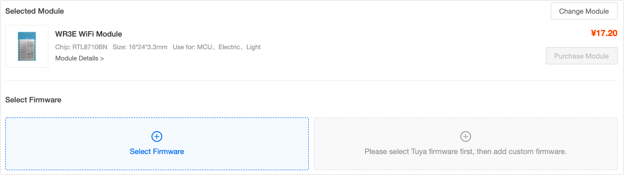
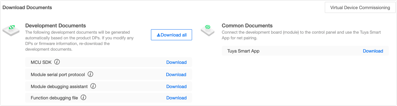
In the Hardware Development stage, select the Tuya module SDK development method and the appropriate module, and download the SDK and function debugging files.
Demo directory structure
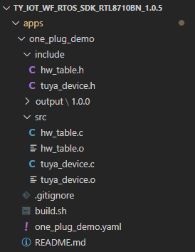
After decompressing the SDK development package, you can find the demo routines in the apps folder. Take the socket demo as an example. The directory structure is as follows.
The files included in the demo project are described in the following table.
| File name | Description |
|---|---|
tuya_device.c |
Include device initialization, feature codes, production test, and more. |
hw_table.c |
Hardware initialization and control operations. |
tuya_device.h |
Header file, which contains key parameter of the key firmware. |
hw_table.h |
Header file, hardware control interface, and more. |
Demo code description
This section describes how the demo code implements the socket features, and how to develop the application code.
Communication logic
The logic of interaction between devices and Tuya Cloud is summarized as follows:
-
Tuya devices interact with the cloud in JSON data. The data identification and definition are configured in the Step 1 Function Definition on the Tuya Developer Platform. The data point (DP) information is defined through
typedefin thetuya_device.hfile.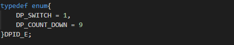
-
The product ID (PID) is generated when a product is created on the Tuya Developer Platform. As the unique identifier of a device, the PID is bound with product configurations, such as app UI, cloud configuration, and voice-enabled features. Therefore, the PID must be written to the code. In the demo code, the PID is written to
tuya_device.hthrough macro definition.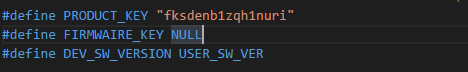
-
Authorization is required to connect the devices to Tuya Cloud. To get the authorization code, see General Wi-Fi SDK Burning and Authorization Instruction.
Note: Currently, you can submit a technical ticket and provide the PID to get the authorization code.
Demo features
The features implemented by the demo are summarized as follows:
| Feature | Implementation |
|---|---|
| Local control | Detect the button I/O port status, control output signals of the relay I/O port to control the relay, and report the status of the online devices to the cloud. |
| Enter pairing status | Detect the button I/O port status. If it is detected that the button is pressed for a certain period of time (five seconds), call the reset function to make the device enter the pairing status. |
| Status indication | Check the current status of the device, and indicate different statuses through the LED, which can be on, off, fast flickering, or slow flickering. |
| Pair with the app | Tuya SDK packages this part of the code. After the device enters the pairing status, select the pairing method on the app, without writing any code. |
| Control with the app | Parse the data sent by the app to control the hardware and report the status to the cloud. |
| Remove with the app | Call the removal interface to control the device to enter the pairing status. |
| Voice control | This part of the code has the same principle as the app controls the device. |
| On/off timing | Start the software timer, update the countdown at fixed intervals, and control the device to respond to specific actions when the time is up. |
| Power-off memory | Control the device to start a timer when reaching a status, set the time, and write the current status of the device to the flash when the time is up. After the next power-on, read the device status parameters from the flash, and control the device to ensure the device is in the status before the power-off. |
| OTA updates | Receive the firmware updates from the cloud, and run updates. |
| Production test | Scan the test SSID, determine whether the signal strength meets the requirements, and give corresponding indications. |
Implementation
Before understanding how the demo code implements device management and control, you must get to know the SDK initialization process.
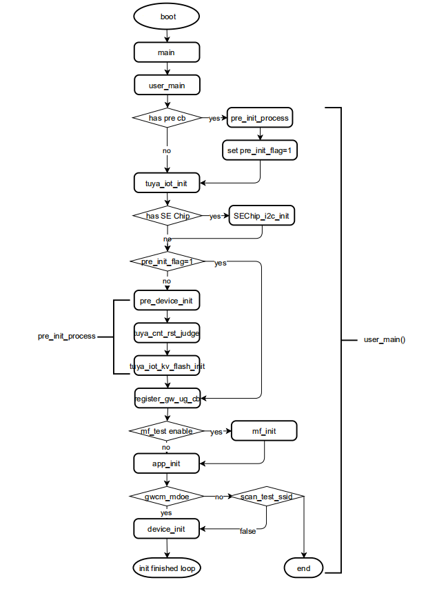
In the entire process, focus on four functions to implement application features:
user_main() // Entry point function. Complete SDK initialization by calling the following three functions
pre_device_init() // View SDK version and set log output
app_init() // Set the working mode of the Wi-Fi module, and register the production test callback function
device_init() // Register the feature callback function. Complete hardware-related initialization
-
View the SDK version:
// Print SDK information, firmware name and version, and set log printing level VOID pre_device_init(VOID) { OPERATE_RET op_ret = OPRT_OK; PR_DEBUG("%s",tuya_iot_get_sdk_info()); PR_DEBUG("%s:%s",APP_BIN_NAME,DEV_SW_VERSION); PR_NOTICE("firmware compiled at %s %s", __DATE__, __TIME__); SetLogManageAttr(TY_LOG_LEVEL_INFO); } -
Set the working mode of the Wi-Fi module:
// Set the working mode of the Wi-Fi module VOID app_init(VOID) { app_cfg_set(GWCM_LOW_POWER,prod_test); } -
Complete the hardware initialization and register the callback function:
// Complete the hardware initialization and register the callback function
OPERATE_RET device_init(VOID)
{
OPERATE_RET op_ret = OPRT_OK;
// Callback function related to feature code
    TY_IOT_CBS_S wf_cbs = {
        status_changed_cb,\
        gw_ug_inform_cb,\
        gw_reset_cb,\
        dev_obj_dp_cb,\
        dev_raw_dp_cb,\
        dev_dp_query_cb,\
        NULL,
};
//  IoT framework initialization
    op_ret = tuya_iot_wf_soc_dev_init_param(func_select.gwcm_mode_user, WF_START_SMART_FIRST, &wf_cbs, FIRMWAIRE_KEY, PRODUCT_KEY, DEV_SW_VERSION);
    if(OPRT_OK != op_ret) {
        PR_ERR("tuya_iot_wf_soc_dev_init err:%d",op_ret);
        return op_ret;
}
// Hardware initialization
    op_ret = init_hw(&g_hw_table);
    if(OPRT_OK != op_ret) {
        PR_ERR("init_hw err:%d",op_ret);
        return op_ret;
    }
    // Callback function of querying the status of Wi-Fi module
    op_ret = tuya_iot_reg_get_wf_nw_stat_cb(__get_wf_status);
    if(OPRT_OK != op_ret) {
    PR_ERR("tuya_iot_reg_get_wf_nw_stat_cb err:%d",op_ret);
        return op_ret;
        }
    // Callback function of saving status, countdown, and Wi-Fi indication status
    op_ret = differ_init();
    if(OPRT_OK != op_ret) {
        PR_ERR("differ_init err:%d",op_ret);
        return op_ret;
}
// Callback function of querying memory status, used to determine whether the program memory works properly
    op_ret = sys_add_timer(memory_left_timer_cb, NULL, &func_select.memory_left_timer);
    if(OPRT_OK != op_ret) {
        return op_ret;
    }else {
        sys_start_timer(func_select.memory_left_timer,2*1000,TIMER_CYCLE);
    }
    INT_T size = tuya_hal_system_getheapsize();
    PR_DEBUG("device_init ok  free_mem_size:%d",size);
    return OPRT_OK;
}

// Implementation of countdown, power-off memory, and other features
STATIC OPERATE_RET differ_init(VOID)
{
    OPERATE_RET op_ret = OPRT_OK;

    if(func_select.is_save_stat) {
        PR_DEBUG("is_save_stat = %d",func_select.is_save_stat);
        read_saved_stat();

        op_ret = sys_add_timer(save_stat_timer_cb, NULL, &func_select.save_stat_timer);
        if(OPRT_OK != op_ret) {
            return op_ret;
        }
    }

    if(func_select.is_count_down) {
        op_ret = sys_add_timer(cd_timer_cb, NULL, &func_select.cd_timer);
        if(OPRT_OK != op_ret) {
            return op_ret;
        }else {
            PR_NOTICE("cd_timer ID:%d",func_select.cd_timer);
            sys_start_timer(func_select.cd_timer, 1000, TIMER_CYCLE);
        }
    }

    op_ret = sys_add_timer(wf_timer_cb,NULL, &func_select.wf_timer);
    if(OPRT_OK != op_ret) {
        PR_ERR("sys_add_timer failed! op_ret:%d", op_ret);
        return op_ret;
    }

    return OPRT_OK;
}
The following sections describe the feature code. Some functions can implement multiple features. Therefore, the relevant part of the code for specific features is displayed, and the other part of the code is replaced by *****.
Local control
// Call the processing function for hardware initialization
HW_TABLE g_hw_table =
{
    .wifi_stat_led.io_cfg = {.type = IO_DRIVE_LEVEL_LOW, .pin = TY_GPIOA_0},
    .rst_button = {TY_GPIOA_5,TRUE,LP_ONCE_TRIG,KEY_RST_TIME,50,key_process},
    .channels = channels
};

VOID key_process(IN TY_GPIO_PORT_E port, IN PUSH_KEY_TYPE_E type, IN INT_T cnt)
{
    *******************
   else if(NORMAL_KEY == type) {
        if(g_hw_table.rst_button.port== port) {
            BOOL_T is_every_active = hw_get_all_channel_stat();
            hw_trig_all_channel(is_every_active);

            if(func_select.is_save_stat) {
                sys_start_timer(func_select.save_stat_timer, 5000, TIMER_ONCE);
           }

            op_ret = upload_all_dp_stat();
            if(OPRT_OK != op_ret) {
                PR_ERR("upload_channel_stat op_ret:%d",op_ret);
                return op_ret;
            }
        }
    }
}
// Configure relay control pin
STATIC CTRL_CHANNEL channels[] =
{
    {
        .relay  = {.type = IO_DRIVE_LEVEL_HIGH, .pin = TY_GPIOA_14},
        .button = {TY_GPIOA_5,TRUE,LP_INVALID,0,50,NULL},
        .led.io_cfg = {.type = IO_DRIVE_LEVEL_NOT_EXIST },
        .dpid   = DP_SWITCH,
        .cd_dpid = DP_COUNT_DOWN,
        .prtest_swti1_count = 0
    }
}
// Configure indicator control pin
STATIC OPERATE_RET led_pin_reg(INOUT OUT_PUT_S *output)
{
    OPERATE_RET op_ret;

    if(NULL == output) {
        PR_ERR("NULL pointer");
        return OPRT_INVALID_PARM;
    }
    if(!IS_IO_TYPE_ALL_PERIPH(output->io_cfg.type)) {
        PR_ERR("IO type not define");
        return OPRT_INVALID_PARM;
    }

    if(output->io_cfg.type != IO_DRIVE_LEVEL_NOT_EXIST) {
       op_ret = tuya_create_led_handle(output->io_cfg.pin,\
                                      IO_ACTIVE_TYPE(output->io_cfg.type),\
                                      &(output->io_handle));
       if(OPRT_OK != op_ret) {
            PR_ERR("op_ret =%d",op_ret);
            return op_ret;
       }
    }
    return OPRT_OK;
}
Enter pairing status
Tuya module SDK supports two pairing methods, namely Wi-Fi Easy Connect and access point (AP) pairing, corresponding to the EZ Mode and AP Mode on the Tuya app.
In this demo, you can switch between pairing mode by pressing and holding the control key. Register the key processing function key_process in g_hw_table. When the pressing and holding action is executed, tuya_iot_wf_gw_unactive is called to control the device to enter pairing. The pairing status is switched cyclically.
- When the device is not in the pairing status, call
tuya_iot_wf_gw_unactiveto enter Wi-Fi Easy Connect. - If the device is in the Wi-Fi Easy Connect status, call
tuya_iot_wf_gw_unactiveto enter AP pairing.
HW_TABLE g_hw_table =
{
    .wifi_stat_led.io_cfg = {.type = IO_DRIVE_LEVEL_LOW, .pin = TY_GPIOA_0},
    .rst_button = {TY_GPIOA_5,TRUE,LP_ONCE_TRIG,KEY_RST_TIME,50,key_process},
    .channels = channels
};

VOID key_process(IN TY_GPIO_PORT_E port, IN PUSH_KEY_TYPE_E type, IN INT_T cnt)
{
    *******************
    if(LONG_KEY == type) {
        if(g_hw_table.rst_button.port== port) {
            PR_NOTICE("LONG PRESS KEY!");
            op_ret = tuya_iot_wf_gw_unactive();
            if(OPRT_OK != op_ret) {
                PR_ERR("tuya_iot_wf_gw_unactive op_ret:%d",op_ret);
                return;
            }
        }
    }
    *******************
}
Query network status
When the network status changes, the tuya_iot_reg_get_wf_nw_stat_cb callback function in the device_init calls __get_wf_status to query device status through hw_set_wifi_led_stat.
OPERATE_RET device_init(VOID)
{
  *****************************
    op_ret = tuya_iot_reg_get_wf_nw_stat_cb(__get_wf_status);
    if(OPRT_OK != op_ret) {
    PR_ERR("tuya_iot_reg_get_wf_nw_stat_cb err:%d",op_ret);
        return op_ret;
        }
  *****************************
 }

STATIC VOID __get_wf_status(IN CONST GW_WIFI_NW_STAT_E stat)
{
    OPERATE_RET op_ret = OPRT_OK;
    func_select.sys_wifi_stat = stat;
    hw_set_wifi_led_stat(stat);

    STATIC BOOL_T proc_flag = FALSE;
    if((STAT_STA_CONN <= stat)&&(proc_flag == FALSE)) {
        op_ret = upload_all_dp_stat();
        if(OPRT_OK != op_ret) {
            PR_ERR("upload_all_dp_stat op_ret:%d",op_ret);
            return;
        }
        proc_flag = TRUE;
    }
    return;
}
Pair with the app
According to the current status of the device, the app selects the pairing method to pair with devices. This part of the code has been implemented in the SDK and does not require you to develop it.
Note: After the pairing is successful, the device will call
Start_boot_upto reboot once, and report the current status of all DPs to the cloud for display on the app control panel.
// When the device is connected to the cloud, `Start_boot_up` is called to reboot once to report the current status of all DPs for display on the app panel
VOID Start_boot_up(VOID)
{
    OPERATE_RET op_ret = OPRT_OK;
    op_ret = upload_all_dp_stat();
    if(OPRT_OK != op_ret) {
        PR_ERR("upload_channel_stat op_ret:%d",op_ret);
        return;
    }
}

OPERATE_RET upload_all_dp_stat(VOID)
{
    OPERATE_RET op_ret = OPRT_OK;
    INT_T count_sec = 0;
    INT_T ch_idx = 0, dp_idx = 0;
    INT_T dp_cnt = 0;

    if(func_select.is_count_down) {
        dp_cnt = g_hw_table.channel_num*2;
    }else {
        dp_cnt = g_hw_table.channel_num;
    }

    TY_OBJ_DP_S *dp_arr = (TY_OBJ_DP_S *)Malloc(dp_cnt*SIZEOF(TY_OBJ_DP_S));
    if(NULL == dp_arr) {
        PR_ERR("malloc failed");
        return OPRT_MALLOC_FAILED;
    }

    memset(dp_arr, 0, dp_cnt*SIZEOF(TY_OBJ_DP_S));
    for(ch_idx = 0,dp_idx = 0; (ch_idx < g_hw_table.channel_num)&&(dp_idx < dp_cnt); ch_idx++,dp_idx++) {
        dp_arr[dp_idx].dpid = get_channel_dpid(ch_idx);
        dp_arr[dp_idx].type = PROP_BOOL;
        dp_arr[dp_idx].time_stamp = 0;
        dp_arr[dp_idx].value.dp_bool = get_channel_stat(ch_idx);

        if(func_select.is_count_down) {
            dp_idx++;
            dp_arr[dp_idx].dpid = get_channel_cddpid(ch_idx);
            dp_arr[dp_idx].type = PROP_VALUE;
            dp_arr[dp_idx].time_stamp = 0;
            if(g_hw_table.channels[ch_idx].cd_sec >= 0) {
                dp_arr[dp_idx].value.dp_value = g_hw_table.channels[ch_idx].cd_sec;//get_cd_remain_sec(ch_idx);
            }else {
                dp_arr[dp_idx].value.dp_value = 0;
            }
        }
    }

    op_ret = dev_report_dp_json_async(get_gw_cntl()->gw_if.id,dp_arr,dp_cnt);
    Free(dp_arr);
    dp_arr = NULL;
    if(OPRT_OK != op_ret) {
        PR_ERR("dev_report_dp_json_async op_ret:%d",op_ret);
        return op_ret;
    }

    return OPRT_OK;
}
Control with the app
In the device_init function, register the DP data processing callback function dev_obj_dp_cb. When the app receives data, dev_obj_dp_cb calls deal_dps_proc to process the received DP data and executes the related hardware, and then calls dev_report_dp_json_async to return the status to the app.
OPERATE_RET device_init(VOID)
{
   ***************************
    TY_IOT_CBS_S wf_cbs = {
        status_changed_cb,\
        gw_ug_inform_cb,\
        gw_reset_cb,\
        dev_obj_dp_cb,\
        dev_raw_dp_cb,\
        dev_dp_query_cb,\
        NULL,
    };
   ****************************
}

VOID dev_obj_dp_cb(IN CONST TY_RECV_OBJ_DP_S *dp)
{
    PR_DEBUG("dp->cid:%s dp->dps_cnt:%d",dp->cid,dp->dps_cnt);
    deal_dps_proc(dp);
}

STATIC VOID deal_dps_proc(IN CONST TY_RECV_OBJ_DP_S *dp)
{
    OPERATE_RET op_ret = OPRT_OK;
    INT_T i = 0,ch_index;
    for(i = 0;i < dp->dps_cnt;i++) {
        PR_DEBUG("dpid:%d type:%d time_stamp:%d",dp->dps[i].dpid,dp->dps[i].type,dp->dps[i].time_stamp);
        switch(dp->dps[i].dpid) {
            case DP_SWITCH: {
                ch_index = hw_set_channel_by_dpid(dp->dps[i].dpid, dp->dps[i].value.dp_bool);
                if( ch_index >= 0) {
                    if((func_select.is_count_down)&&(g_hw_table.channels[ch_index].cd_sec >= 0)) {
                        g_hw_table.channels[ch_index].cd_sec = -1;
                    }
                    op_ret = upload_channel_stat(ch_index);
                    if(OPRT_OK != op_ret) {
                        PR_ERR("upload_channel_stat op_ret:%d",op_ret);
                        break;
                    }
                }
                if(func_select.is_save_stat) {
                    sys_start_timer(func_select.save_stat_timer, 5000, TIMER_ONCE);
                }
            }
            break;

            case DP_COUNT_DOWN: {
                ch_index = hw_find_channel_by_cd_dpid(dp->dps[i].dpid);
                if(ch_index >= 0) {
                    if(dp->dps[i].value.dp_value == 0) {
                        g_hw_table.channels[ch_index].cd_sec = -1;
                    }else {
                        g_hw_table.channels[ch_index].cd_sec = dp->dps[i].value.dp_value;
                    }
                    op_ret = upload_channel_stat(ch_index);
                    if(OPRT_OK != op_ret) {
                        PR_ERR("upload_channel_stat op_ret:%d",op_ret);
                        break;
                    }
                }
            }
            break;

            default:
            break;
        }
    }
}

OPERATE_RET upload_channel_stat(IN UINT_T ch_idx)
{
    OPERATE_RET op_ret = OPRT_OK;

    INT_T count_sec = 0;
    INT_T dp_idx = 0;
    INT_T dp_cnt = 0;

    dp_cnt = (func_select.is_count_down)?2:1;
    TY_OBJ_DP_S *dp_arr = (TY_OBJ_DP_S *)Malloc(dp_cnt*SIZEOF(TY_OBJ_DP_S));
    if(NULL == dp_arr) {
        PR_ERR("malloc failed");
        return OPRT_MALLOC_FAILED;
    }

    memset(dp_arr, 0, dp_cnt*SIZEOF(TY_OBJ_DP_S));

    dp_arr[dp_idx].dpid = get_channel_dpid(ch_idx);
    dp_arr[dp_idx].type = PROP_BOOL;
    dp_arr[dp_idx].time_stamp = 0;
    dp_arr[dp_idx].value.dp_bool = get_channel_stat(ch_idx);
    dp_idx ++;

    if(func_select.is_count_down) {
        dp_arr[dp_idx].dpid = get_channel_cddpid(ch_idx);
        dp_arr[dp_idx].type = PROP_VALUE;
        dp_arr[dp_idx].time_stamp = 0;
        if(g_hw_table.channels[ch_idx].cd_sec >= 0) {
            dp_arr[dp_idx].value.dp_value = g_hw_table.channels[ch_idx].cd_sec;//get_cd_remain_sec(ch_idx);
        }else {
            dp_arr[dp_idx].value.dp_value = 0;
        }
        dp_idx ++;
    }

    if(dp_idx != dp_cnt) {
        PR_ERR("dp_idx:%d,dp_cnt:%d",dp_idx,dp_cnt);
        Free(dp_arr);
        dp_arr = NULL;
        return OPRT_COM_ERROR;
    }

    op_ret = dev_report_dp_json_async(get_gw_cntl()->gw_if.id,dp_arr,dp_cnt);
    Free(dp_arr);
    dp_arr = NULL;
    if(OPRT_OK != op_ret) {
        PR_ERR("dev_report_dp_json_async op_ret:%d",op_ret);
        return op_ret;
    }

    return OPRT_OK;
}
// The app queries the device status
VOID dev_dp_query_cb(IN CONST TY_DP_QUERY_S *dp_qry)
{
    PR_DEBUG("Recv DP Query Cmd");
    OPERATE_RET op_ret = OPRT_OK;
    op_ret = upload_all_dp_stat();
    if(OPRT_OK != op_ret) {
        PR_ERR("upload_all_dp_stat op_ret:%d",op_ret);
        return;
    }
}
Remove with the app
To remove the device with the app, after the device receives the removal command, gw_reset_cb is called to reset the device and the device enters pairing.
VOID gw_reset_cb(IN CONST GW_RESET_TYPE_E type)
{
    OPERATE_RET op_ret = OPRT_OK;
    if(GW_REMOTE_RESET_FACTORY != type) {
        return;
    }

    if(func_select.is_save_stat) {
        // Disable the setting of restoring factory defaults after power-on
        op_ret = wd_common_fuzzy_delete(STORE_OFF_MOD);
        if(OPRT_OK != op_ret) {
            PR_ERR("clear power_stat op_ret:%d",op_ret);
        }
    }

    return;
}
Voice control
Voice control is implemented in the same way as the app control. For more information, see Pair with the app, Control with the app, and Remove with the app.
Note: You must enable the voice feature in the value-added services on the Tuya Developer Platform before using voice control. For more information, see Third-party Access.
Countdown switch
Enable the countdown feature in func_select, If differ_init determines that the countdown feature is true, the software timer will register the cd_timer_cb callback function and update the countdown every 30 seconds. Corresponding actions will be executed after the countdown ends.
STATIC OPERATE_RET differ_init(VOID)
{
    OPERATE_RET op_ret = OPRT_OK;
    *******************************
    if(func_select.is_count_down) {
        op_ret = sys_add_timer(cd_timer_cb, NULL, &func_select.cd_timer);
        if(OPRT_OK != op_ret) {
            return op_ret;
        }else {
            PR_NOTICE("cd_timer ID:%d",func_select.cd_timer);
            sys_start_timer(func_select.cd_timer, 1000, TIMER_CYCLE);
        }
    }

    op_ret = sys_add_timer(wf_timer_cb,NULL, &func_select.wf_timer);
    if(OPRT_OK != op_ret) {
        PR_ERR("sys_add_timer failed! op_ret:%d", op_ret);
        return op_ret;
    }

    return OPRT_OK;
}

FUNC_SELECT func_select = {
    .is_save_stat =  FALSE,
    .is_count_down = TRUE,
    .gwcm_mode_user = GWCM_SPCL_MODE,
    .cd_upload_period = 30,
    .prod_flag = FALSE
};

STATIC VOID cd_timer_cb(IN UINT_T timerID, IN PVOID pTimerArg)
{
    UCHAR_T i = 0;
    OPERATE_RET op_ret = OPRT_OK;

    for(i = 0; i<g_hw_table.channel_num; i++) {
        if(g_hw_table.channels[i].cd_sec < 0) {
            continue;
        }else {
            --g_hw_table.channels[i].cd_sec;
            if(g_hw_table.channels[i].cd_sec <= 0) {
                g_hw_table.channels[i].cd_sec = -1;
                hw_trig_channel(i);
                op_ret = upload_channel_stat(i);
                if(OPRT_OK != op_ret) {
                    PR_ERR("upload_channel_stat op_ret:%d",op_ret);
                    return ;
                }
            }else {
                if(g_hw_table.channels[i].cd_sec % 30 == 0) {
                    op_ret = upload_channel_stat(i);
                    if(OPRT_OK != op_ret) {
                        PR_ERR("upload_channel_stat op_ret:%d",op_ret);
                        return;
                    }
                }
            }
        }
    }
}
Power-off memory
Enable the power-off memory feature in func_select, If differ_init determines that the power-off memory feature is true, the software timer will register the save_stat_timer_cb callback function and call wd_common_write every five seconds to write the current status to the flash.
During the next power-on, call read_saved_stat to read the current status from flash, and control the device to enter this status. The power-off memory is achieved and the status is sent to the app for display.
#define STORE_OFF_MOD "save_off_stat"
#define STORE_CHANGE "init_stat_save"

FUNC_SELECT func_select = {
    .is_save_stat =  FALSE,
    .is_count_down = TRUE,
    .gwcm_mode_user = GWCM_SPCL_MODE,
    .cd_upload_period = 30,
    .prod_flag = FALSE
};

STATIC VOID save_stat_timer_cb(IN UINT_T timerID,IN PVOID pTimerArg)
{
    OPERATE_RET op_ret = OPRT_OK;
    INT_T i;

    PR_DEBUG("save stat");
    IN CONST BYTE_T buff[48] = "{\"power\":[";
    for(i=0; i<g_hw_table.channel_num; ++i) {
        if(g_hw_table.channels[i].stat) {
            strcat(buff, "true");
        }
        else if(!g_hw_table.channels[i].stat) {
            strcat(buff, "false");
        }

        if(i < g_hw_table.channel_num -1) {
            strcat(buff, ",");
        }else {
            strcat(buff, "]}");
        }
    }
    PR_DEBUG("%s", buff);

    op_ret = wd_common_write(STORE_OFF_MOD,buff,strlen(buff));
    if(OPRT_OK != op_ret) {
        PR_DEBUG("kvs_write err:%02x",op_ret);
    }
}

VOID read_saved_stat(VOID)
{
    PR_DEBUG("_______________SAVE________________");
    OPERATE_RET op_ret = OPRT_OK;
    cJSON *root = NULL, *js_power = NULL, *js_ch_stat = NULL;
    UINT_T buff_len = 0;
    UCHAR_T *buff = NULL;

    INT_T i;
    op_ret = wd_common_read(STORE_OFF_MOD,&buff,&buff_len);
    if(OPRT_OK != op_ret) {
        PR_DEBUG("msf_get_single err:%02x",op_ret);
        return;
    }
    PR_DEBUG("read stat: %s", buff);
    root = cJSON_Parse(buff);
    Free(buff);
    if(NULL == root) {
        PR_ERR("cjson parse err");
        return;
    }

    js_power = cJSON_GetObjectItem(root, "power");
    if(NULL == js_power) {
        PR_ERR("cjson get power error");
        goto JSON_PARSE_ERR;
    }

    UCHAR_T count = cJSON_GetArraySize(js_power);
    if(count != g_hw_table.channel_num) {
        for(i = 0;i< g_hw_table.channel_num; ++i) {
            hw_set_channel(i, FALSE);
        }
        return;
    }

    for(i=0; i< g_hw_table.channel_num; ++i) {
        js_ch_stat = cJSON_GetArrayItem(js_power, i);
        if(js_ch_stat == NULL) {
            PR_ERR("cjson %d ch stat not found", i);
            goto JSON_PARSE_ERR;
        }else {
            if(js_ch_stat->type == cJSON_True) {
                hw_set_channel(i, TRUE);
            }else {
                hw_set_channel(i, FALSE);
            }
        }
    }
JSON_PARSE_ERR:
    cJSON_Delete(root); root = NULL;

}
OTA updates
Configure the updates on the Tuya Developer Platform. After receiving the update notification, the device calls the gw_ug_inform_cb callback function to run updates.
VOID gw_ug_inform_cb(IN CONST FW_UG_S *fw)
{
    PR_DEBUG("Rev GW Upgrade Info");
    PR_DEBUG("fw->fw_url:%s", fw->fw_url);
   //PR_DEBUG("fw->fw_md5:%s", fw->fw_md5);
    PR_DEBUG("fw->sw_ver:%s", fw->sw_ver);
    PR_DEBUG("fw->file_size:%d", fw->file_size);

    tuya_iot_upgrade_gw(fw, get_file_data_cb, upgrade_notify_cb, NULL);
}

OPERATE_RET get_file_data_cb(IN CONST FW_UG_S *fw, IN CONST UINT_T total_len, IN CONST UINT_T offset,IN CONST BYTE_T *data, IN CONST UINT_T len, OUT UINT_T *remain_len, IN PVOID pri_data)
{
    PR_DEBUG("Rev File Data");
    PR_DEBUG("Total_len:%d ", total_len);
    PR_DEBUG("Offset:%d Len:%d", offset, len);

    return OPRT_OK;
}

VOID upgrade_notify_cb(IN CONST FW_UG_S *fw, IN CONST INT_T download_result, IN PVOID pri_data)
{
    PR_DEBUG("download  Finish");
    PR_DEBUG("download_result:%d", download_result);
}
Production test
Register the production test function through app_cfg_set in app_init, and scan the TEST_SSID defined in tuya_main.c to determine the signal strength.
-
If the signal strength is greater than -60 dB, the device signal is qualified. The software timer is started, and the
protest_switch_timer_cbcallback function is called to perform a functional test. -
If the signal strength is less than -60 dB, the device signal is poor, and instructions are given to guide the user to troubleshoot.
#define TEST_SSID "tuya_mdev_test1"

VOID app_init(VOID)
{
    app_cfg_set(GWCM_LOW_POWER,prod_test);
}

STATIC VOID prod_test(IN BOOL_T flag, IN CHAR_T rssi)
{
    OPERATE_RET op_ret = OPRT_OK;
    PR_DEBUG("dev_test_start_cb");
    PR_DEBUG("rssi:%d", rssi);

    if((rssi<-60) ||(flag == FALSE)) {
        PR_ERR("rssi:%d,flag:%d",rssi,flag);
        return;
    }

    op_ret = sys_add_timer(protest_switch_timer_cb,NULL,&g_hw_table.switch_timer);
    if(OPRT_OK != op_ret) {
        PR_ERR("sys_add_timer switch_timer err");
        return ;
    }

    op_ret = prod_test_init_hw(&g_hw_table);
    if(OPRT_OK != op_ret) {
        PR_ERR("prod_test_init_hw err");
        return ;
    }

    func_select.prod_flag = TRUE;
}

STATIC VOID protest_switch_timer_cb(IN UINT timerID, IN PVOID pTimerArg)
{
    STATIC UCHAR_T act_cnt = 0;
    STATIC UCHAR_T target_ch = 0;

    PR_DEBUG("all relay timer callback");

    if( target_ch < get_all_ch_num()) {
        hw_trig_channel(target_ch);
        act_cnt++;
    }

    if(target_ch >= get_all_ch_num()) {
        act_cnt = 0;
        target_ch = 0;
    }else if(act_cnt < 6) {
        sys_start_timer(g_hw_table.switch_timer, RELAY_ACT_INTER, TIMER_ONCE);
    }else{
        act_cnt = 0;
        target_ch++;
        sys_start_timer(g_hw_table.switch_timer, RELAY_ACT_INTER, TIMER_ONCE);
    }
}
During development, add the monitoring function and print logs, in order to discover and solve problems timely. In the demo code, the software timer is started and the memory_left_timer_cb callback function is called to monitor the memory and confirm that the device is operating properly.
OPERATE_RET device_init(VOID)
{
    **************************************
    op_ret = sys_add_timer(memory_left_timer_cb, NULL, &func_select.memory_left_timer);
    if(OPRT_OK != op_ret) {
        return op_ret;
    }else {
        sys_start_timer(func_select.memory_left_timer,2*1000,TIMER_CYCLE);
    }

    INT_T size = tuya_hal_system_getheapsize();
    PR_DEBUG("device_init ok  free_mem_size:%d",size);
    return OPRT_OK;
}
Compile the firmware
Compilation scripts are provided in the SDK. You can use the following commands to call the scripts to compile code.
-
Compilation command: Enter the directory where the compilation script is located, and execute
./build_app.sh apps/<project name> <project name> <version number>. -
Example:
./build_app.sh apps/one_plug_demo one_plug_demo 1.0.0
After successful compilation, a binary (.bin) file for burning will be generated in the apps/project name/output/version number/xxx.bin directory, as shown in the following picture:
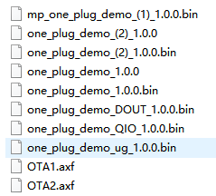
In the compiled .bin file, the production firmware file name contains extension of QIO and DOUT. During production, you can select the applicable firmware according to your flash tool. The file name of the user firmware contains _(1) and _(2), used for debugging phase. The name of the update firmware contains _ug, used for OTA update.
| File name | Description |
|---|---|
| one_plug_demo_(1)_1.0.0.bin | User firmware, used for chip burning tool. |
| one_plug_demo_(2)_1.0.0.bin | User firmware, used for chip burning tool. |
| one_plug_demo_DOUT_1.0.0.bin | Production firmware, used to flash modules in DOUT mode. |
| one_plug_demo_QIO_1.0.0.bin | Production firmware, used to flash modules in QIO mode. |
| one_plug_demo_ug_1.0.0.bin | Firmware updates, used to upload the user firmware and OTA firmware on the Tuya Developer Platform. |
Burning authorization
Upload the firmware to the Tuya Developer Platform, apply for an authorization code, and write the authorization information through the Tuya Cloud Module Burning Authorization Platform. For more information, see General Wi-Fi SDK Burning and Authorization Instruction.
Log level
During debugging, you can monitor the running status of the device and debug the code by printing logs.
The log levels of Tuya general SDK are classified into the following categories:
- Notice
- Warning
- Error
- Debug
You can decide which log to output by setting the log level. For example, if you set the log output level to TY_LOG_LEVEL_INFO, ERROR, WARN, NOTICE, and INFO information will be displayed, but DEBUG and TRACE will not be displayed.
/* tuya sdk definition of log level */
typedef INT_T LOG_LEVEL;
#define TY_LOG_LEVEL_ERR 0 // Error message, which should not occur when the program runs correctly
#define TY_LOG_LEVEL_WARN 1 // Warning message
#define TY_LOG_LEVEL_NOTICE 2 // Notice that needs attention
#define TY_LOG_LEVEL_INFO 3 // Information
#define TY_LOG_LEVEL_DEBUG 4 // Program debugging information, to be deleted in the release version
#define TY_LOG_LEVEL_TRACE 5 // Program running path information, to be deleted in the release version
Is this page helpful?
YesFeedbackIs this page helpful?
YesFeedback


