3, 3S, and 3L Series SMT Application Guide
Purpose
This topic describes the important notes and suggestions on 3, 3S, and 3L series packaging for SMT network modules. You can reduce the problems that might occur during production and improve the yield of SMT.
Scope
This topic is applicable to 3, 3S, and 3L series packaging for SMT network modules provided by Tuya.
References
- 3, 3S, and 3L Series SMT Network Modules Datasheet
- IPC-7525 Stencil Design Guidelines
- IPC-7527 Requirements for Solder Paste Printing
- J-STD-033 Handling, Packing, Shipping and Use of Moisture, Reflow, and Process Sensitive Devices
- IPC-7530 Guidelines for Temperature Profiling for Mass Soldering Processes (Reflow & Wave)
Module packaging
The following figure shows reference information about tape and reel packaging. In this example, 44 mm-width feeders are used at a pitch of 24 mm.
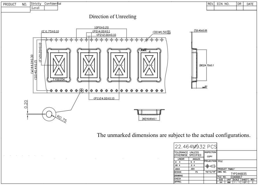
- The cumulative error of 10 round sprocket holes is within ±0.2 mm.
- The bend of a 100 mm tape cannot be more than 1 mm.
- Put up to 900 components on a plastic reel with a 15-inch diameter. The hub of the reel is 100 mm in diameter. Production meters: 22.464m. Keep 10 empty pockets at the start and 10 empty pockets at the end. Each reel has 12 pockets reserved for component wastage.
- Material: The carrier reel is constructed from black polystyrene (PS) film of the PSF-11-X model (double-sided ESD protection).
- Stick a label on the outer package. No label is required on the reel inside the package.
- Add a protection band outside the outermost carrier tape. Specifications of the protection band: 44 mm × 1.0 mm × 1,200 mm.
Confirm module before production
Check relative humidity indicator
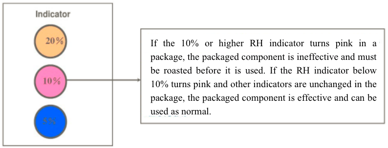
Open its vacuum package and check the relative humidity indicator. If the 10% or higher relative humidity indicator turns pink, as shown in the following figure, the component might be damp and must be baked before it is used.
Treat unpacked module
Modules are Moisture Sensitivity Level-3 (MSL-3) humidity-sensitive components. After a module is unpacked, the module can be exposed to air for up to 168 hours. If it is exposed for more than 168 hours, it must be baked before you use it. In light of this, stick a label on the package of the module to record the time when it is unpacked. If the production is paused for over 24 hours after the module is unpacked, we recommend that you place the module in a moisture-proof box with a relative humidity level below 10%, or pack the module in vacuum again. Then, record the packing time and duration of exposure.
| MSL | Max exposure duration labeled on package Workshop environment ≤ 30°C/60%RH |
|---|---|
| MSL 1 | Unlimited duration of exposure |
| MSL 2 | 1 year |
| MSL 2a | 4 weeks |
| MSL 3 | 168 hours |
| MSL 4 | 72 hours |
| MSL 5 | 48 hours |
| MSL 5a | 24 hours |
| MSL 6 | Forced baking before use |
Baking conditions
For tape and reel packaging, the module is baked at a temperature of 40°C for 8 days. With a high-temperature resistant tray, the module is baked at a temperature of 125°C for 12 hours. The baking method with a high-temperature resistant tray is recommended.
Suggestions on stencil openings
-
For 3, 3S, and 3L series packaged modules, the thickness of the stencil is recommended to range from 0.15 mm to 0.18 mm. If the overall thickness of the stencil goes beyond this range, a step-up stencil can be used. The stencil front for printing is partially thickened.
-
The following table describes the reference dimensions of stencil openings for 3, 3S, and 3L series packaged modules. The recommended dimensions of packaging pads can vary slightly in different product datasheets. Recommended stencil openings cannot be fully described. In this table, the requirements for typical products with the same overall stencil opening solution are described.
Applicable module model Reference of stencil opening Stencil design requirements TYWE3S, TYWE3L, WR3LE, WR3E, WR3L, WR3N, WBR3N, WBR, WBR3, WBR3D, WBR3T, WBR3S, WBR3N, CB3L, CE3S, AXY3L, AXY3S, WT3, BP3L, BT3L, BT3L-A, BT3L-G, BR3L, TYZS3-IPEX, WR3, TYZS3, ZT3L, BH3L, WRD3L 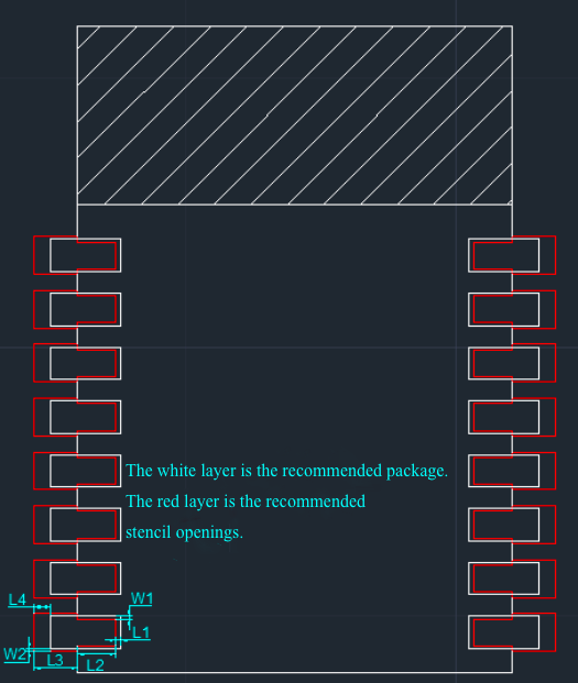
1. The thickness of the stencil is recommended to range from 0.15 mm to 0.18 mm.
2. The stencil openings are shrunk inward by 0.2 mm (as L1 in the figure), and moved outward by 0.4 mm to 0.6 mm (as L4 in the figure) along the direction of length.
3. Along the width direction, the stencil openings are shrunk inward (each side by 0.1 mm, as W1 in the figure) with a length (as L2 in the figure) of the pad covered after SMT.
4. Along the width direction, the stencil openings are moved out by 0.15 mm for each side, as W2 in the figure, with a length of the pad exposed after SMT (as L3 in the figure).Applicable
module modelReference of
stencil openingStencil design
requirementsTYWE3SE, CB3S, CB3SE, CB3S-NL, CR3L, SS3L, WA3, WA3L, WB3L, WB3S, WB3S-IPEX, XR3, ZN3L, ZS3L 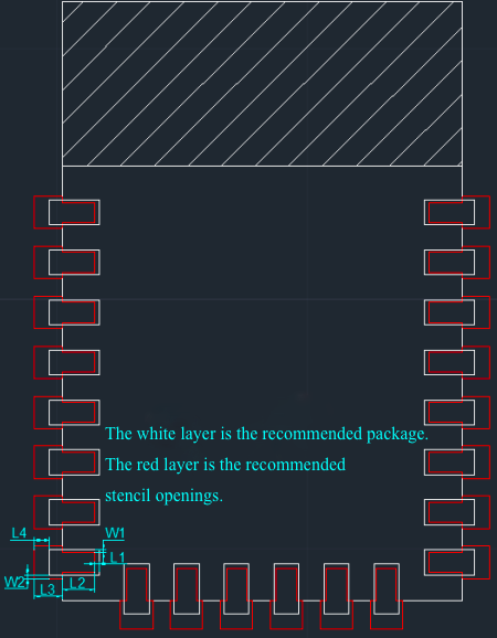
1. The thickness of the stencil is recommended to range from 0.15 mm to 0.18 mm.
2. The stencil openings are shrunk inward by 0.2 mm (as L1 in the figure), and moved outward by 0.4 mm to 0.6 mm (as L4 in the figure) along the direction of length.
3. Along the width direction, the stencil openings are shrunk inward (each side by 0.1 mm, as W1 in the figure) with a length (as L2 in the figure) of the pad covered after SMT.
4. Along the width direction, the stencil openings are moved out by 0.15 mm for each side, as W2 in the figure, with a length of the pad exposed after SMT (as L3 in the figure).- Both diagrams of recommended stencil openings are for reference only. You can optimize the actual dimensions as needed.
- If your module is partially thickened with a step-up stencil, within a distance of 3 mm from the module, we recommend that you do not place 0201 components and those placed at a pitch of less than 0.5 mm. Otherwise, solder bridging might be caused.
- For components located within 1 mm from the area partially thickened with the step-up stencil, the area of stencil openings can be reduced by 10% to 20%, compared with the normal area. This prevents defects caused by excessive solder.
- The pad covered after SMT is shrunk inward to avoid solder beads. Expose the pad outward to ensure the module is soldered as expected.
Suggestions on solder paste printing
-
Solder paste must be strictly managed and controlled as required by the solder paste manufacturer. Before solder paste printing, make sure the solder paste is within its shelf life and has been warmed up and stirred. For more information about the warm-up and stirring duration, see the datasheet of solder paste. If the datasheet is unavailable, we recommend that you warm up the solder paste for 2 to 4 hours and stir it for 1 to 3 minutes if the solder paste is refrigerated at a temperature from 2°C to 10°C. We recommend that you use the solder paste within 24 hours after it is unpacked.
-
Printing parameters are subject to the characteristics of the solder paste product, and printing device. Recommended parameters: The printing speed ranges from 40 mm/s to 70 mm/s. The printing pressure ranges from 0.018 kg to 0.027 kg per the unit length of the scraper in mm. For example, for a 300 mm scraper, the printing pressure ranges from 5.4 kg to 8.1 kg. During printing, the working area of the scraper must have little residual solder paste.
-
Check the quality of solder paste printing.
-
Without a solder paste inspection (SPI) machine, you must arrange for staff to visually inspect the offset, thickness, area, and volume of the solder paste printing.
-
Recommended SPI inspection parameters: Based on the actual stencil openings, the parameters are set for the partially-thickened area separately from that with normal thickness.
- Offset: ±30%
- Thickness: 60%-170%
- Area: 60%-170%
- Volume: 50%-180%
The preceding parameters are for your reference. An SPI device is an optical inspection device. Certain deviations might exist during the inspection. The inspection parameters can be optimized to suit your actual conditions. This helps to locate printing faults prior to the SMT process. Excessive false positive is not recommended.
-
Suggestions on SMT application
-
Before feeding, check whether the 10% relative humidity indicator turns pink in the vacuum package. If so, bake the module in specified baking conditions.
-
Make sure the module is absorbed and mounted with the expected precision. For this purpose, if a tape-and-reel packaged module is unpacked and baked on a high-temperature resistant tray, we recommend that you use a dedicated SMT tray for production. To install a tape-and-reel packaged module, select the feeders with the same width as that of the tape. Adjust the pitch of feeders according to the pitch of the tapes.
-
Select a suction nozzle in a size suitable for suction and SMT application. The diameter of the suction nozzle is recommended to be over 40% of the short side length of the sucked material. Set the suction and SMT speed to low.
-
During image recognition, try to use the back pad of the module for positioning to ensure an image recognition pass rate at 100%. Control the SMT precision to be within ±0.1 mm.
-
Mount the module in the direction strictly along the external frame of the silk screen. The recommended packaging defines the dimensions and direction of the external frame of the silk screen.
Suggestions on reflow soldering
-
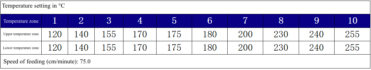
If SAC305 solder paste is used, set the oven temperature of ten temperature zones for the reflow soldering device, as described in the following table. You can adjust the temperature values according to the actual reflow soldering device, printed circuit board (PCB) thickness, and component structure. The oven temperature for all components must fall within the process limits.
-
Oven temperature curve
Use an actual board to create a temperature test board. We recommend that you test the oven temperature each time the product is replaced. During continuous production, test the oven temperature curve once per day. Set the oven temperature curve as recommended in the following process limits.
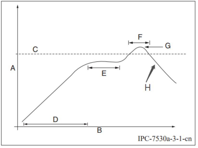
- A: temperature axis
- B: time axis
- C: alloy liquidus temperature from 217°C to 220°C
- D: ramp-up slope from 1°C/s to 3°C/s
- E: constant temperature time from 60s to 120s, constant temperature from 150°C to 200°C
- F: temperature above liquidus temperature for 50s to 70s
- G: peak temperature from 235°C to 245°C
- D: ramp-down slope from 2°C/s to 4°C/s
Suggestions on module dismounting
-
If the product is exposed to air for over 168 hours, we recommend that you bake the product before you disassemble it.
-
To dismount the module, move a heat gun along the edges of the pad at a constant speed to heat the module. After the soldering paste is fully melted, use a pair of tweezers to take the module down. The overall heating duration must be within 100s.
-
After the module is dismounted, cool it down to the environment temperature, and check whether solder bridging occurs on the back pad. If you want to mount the module again, clear the solder on the module pad to make the surface roughness less than 0.1 mm. Place the module on the marble, and use a plug gauge to measure the maximum gap that must be 0.1 mm or less.
-
A module can be repaired up to three times. If it is failed to be repaired after three times, we recommend that you scrap the module.
-
Parameters of the heat gun:
-
Temperature: 350°C
-
Duration: < 100s
-
Wind speed: subject to the actual condition
-
Distance: 1 to 3 cm
During the dismounting process, apply electrostatic discharge (ESD) protection to the tools and workbench. Lay an ESD mat on the workbench. The heat gun and the workbench must be grounded.
-
Is this page helpful?
YesFeedbackIs this page helpful?
YesFeedback


