Extended Features
This topic describes the extended features that are designed to deliver useful IoT-enabled functionalities, including the low power mode, OTA update, production test, and time sync.
All the protocol examples in this topic are performed on the module debugging assistant. This debugger can help you understand how data transmission works.
Bluetooth low energy
The MCU can send the module a command to enable the low power feature. Additionally, the MCU can change the settings of the module, such as changing the advertisement interval and turning off the timer, to maximize power consumption reduction.
How it works
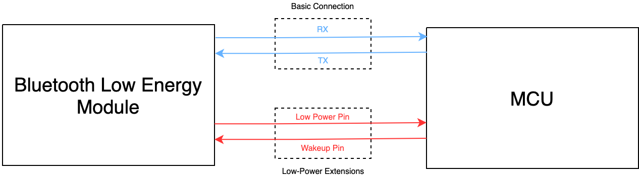
If you do not use the low power feature, you simply connect the TX and RX pins on your MCU to the RX and TX pins on the module to implement the basic serial communication. If you want to implement the low power feature, you also need to connect your MCU to the low power pin on the module.
-
Low power pin: used to make the module enter or exit the low power mode. The MCU can pull down this pin to make the module enter the low power mode. The module will stop serial communication but maintain the Bluetooth connection with the mobile app. The MCU can pull up this pin to wake up the module.
Module model Low power pin Voltage level in low power Voltage level in standard power BT3L-A1, BT3L, BT3L-A, BT3L-G, BT7L-G, BT7L, BT7L-IPEX, and BT2S TL_B5labeled on the silkscreenLow High BT5S TL_C3labeled on the silkscreenLow High The module will wait for 10 milliseconds before receiving serial data after it is woken up from sleep. If the module is woken up from deep sleep, it will be restarted. Therefore, the waiting time will be 600 milliseconds.
-
Wake-up pin: used to wake up the MCU. In the low power mode, the module will change the level of this pin for 10 milliseconds to wake up the MCU for data transmission. After that, the pin will go back to the default level.
Module model Wake-up pin Voltage level on transmitting Voltage level on idle BT3L-A1, BT3L, BT3L-A, BT3L-G, BT7L-G, BT7L, BT7L-IPEX, and BT2S TL_D2labeled on the silkscreenHigh Low BT5S TL_D2labeled on the silkscreenHigh Low Note that the wake-up pin configuration varies depending on chipset platforms. Do not leave the wake-up pin on the MCU floating. Some module models do not support the low power feature. For more information, see Protocols for low power features.
- After the module goes online, it will sync its clock with the system time of the mobile phone. Without an external RTC, the accuracy of the clock inside the Telink-based module is not high. The time drift is less than one minute in 24 hours. If you require highly accurate timekeeping, you can connect an external RTC to the MCU.
- When the supply voltage is below the operating voltage, operations on the flash memory of the module might cause errors in firmware or user data. When the MCU detects a low voltage level, it can perform one of the two operations to prevent such issue:
- Power off the module.
- Turn off advertising and system timer to allow the module to enter deep-sleep mode. The minimum operating voltage for the Telink-based module is 1.8V. You can set the threshold of power-off to 2.0V.
Scenarios
The low power solution is especially useful with devices that operate on batteries and need to conserve as much energy as possible.
The MCU sends the module a command to enable the low power feature. To resume serial communication, the MCU can pull up the low power pin to wake up the module.
Commands
The commands used in the low power mode.
- Enable the low power feature:
0xE5 - Change the advertisement interval in the low power mode:
0xE2 - Turn off system timer:
0xE4 - Disconnect Bluetooth connection proactively:
0xE7 - Configure the low power pin:
0xE3 - Wake up the MCU:
0xB0 - Set the Bluetooth connection interval:
0xB1
For more information, see Protocols for low power features.
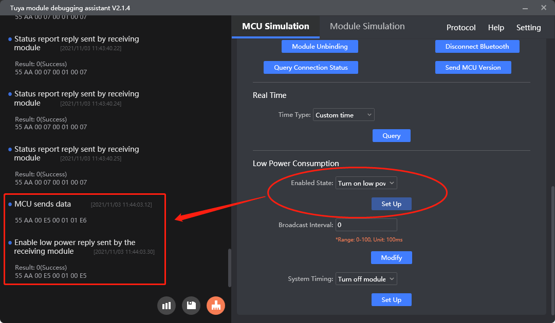
Enable the low power feature (0xE5)
Purpose: Enable the low power feature of the module.
Scenario: If the module defaults to standard power mode, this command can enable the low power feature. After enablement, the MCU can pull down the low power pin to make the module enter the low power mode. This configuration is permanently retained.
- This command is only used to enable the low power feature. The specific power mode depends on the voltage level of the low power pin on the module.
- The smart lock firmware of TYBN1 and BK3431Q does not support enabling the low power feature.
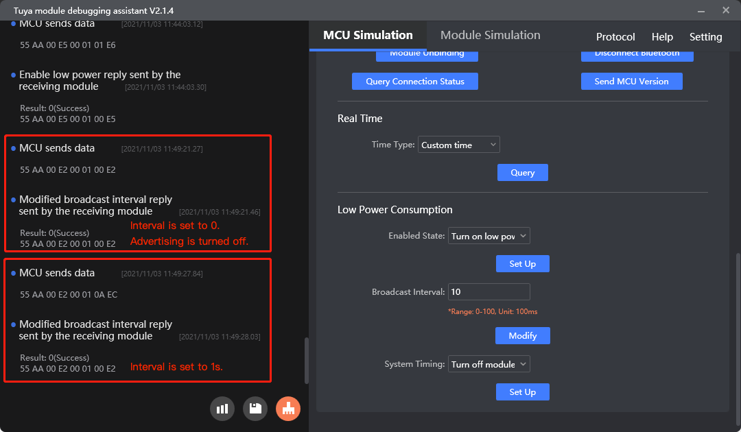
Change the advertisement interval in the low power mode (0xE2)
Purpose: Change the advertisement interval in the low power mode to reduce power consumption.
Scenario: Adjust the advertisement interval in the low power mode to lower power usage. If the interval is set to 0, advertising is turned off. This configuration is permanently retained.
- The value of the advertisement interval ranges from 0 to 20 in units of 100 milliseconds. The advertisement interval defaults to one second in the low power mode. A long interval means taking more time to connect to a mobile phone. If the phone has poor radio performance, the Bluetooth connection attempt might fail.
- The health products firmware of BK3432 does not support this command.
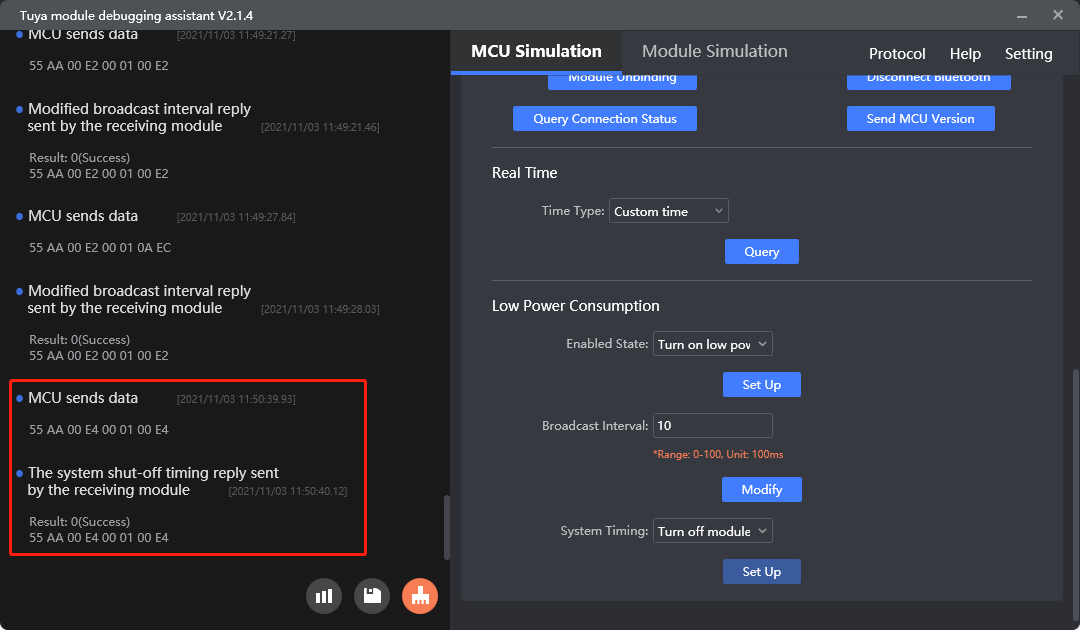
Turn off system timer (0xE4)
Purpose: Turn off the module’s internal timer in the low power mode.
Scenario: If the MCU does not rely on the system time of the module, you can turn off the internal timer of the Telink-based module to reduce the power usage in sleep mode. After both the timer and advertising are turned off, the MCU pulls down the low power pin to make the module enter deep-sleep mode with current consumption reduced to 3 μA. This configuration is permanently retained.
For BK3431Q and TYBN1 modules, writing time data to flash memory is high power consuming and is turned off in sleep mode by default. The timekeeping function is still available because it uses less power. If you turn on the time data writing, the time will be saved to the flash memory every one minute, which can fix the issue of RTC reset after the module is restarted.
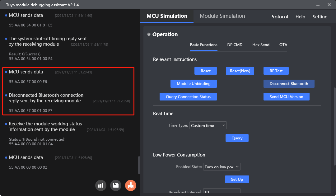
Disconnect Bluetooth connection proactively (0xE7)
Purpose: Disconnect the module from the Bluetooth connection in low power mode.
Scenario: In an idle state, the MCU can send this command to disconnect the module from the Bluetooth connection to maximize power consumption reduction in the low power mode.
This command can work for both the standard and low power modes.
Configure the low power pin (0xE3)
Purpose: Change the default low power pin of the module.
Scenario: You can call this command after the serial initialization to configure a custom GPIO pin for low power mode control. This configuration is permanently retained.
Since the module stops receiving serial data in the low power mode, the MCU must send this command within one second after the module is powered on, or before enabling the low power feature.
This command only applies to the firmware of the BK3432 chip.
Wake up the MCU (0xB0)
Purpose: Set the wake-up time from the low power mode for the MCU.
Scenario: This command applies to smart lock firmware of TYBN1 v6.2 or later and smart lock firmware of BK3431Q v3.3 or later. Set the pull-up time for waking up the MCU in the low power mode. The module needs to pull up the wake-up pin for 200 milliseconds before sending serial data to the MCU by default. After data transmission, it pulls down the pin.
- Wake-up time: The value ranges from 1 to 20, in units of 10 milliseconds. The default value of 200 milliseconds is recommended. After modification, you must verify whether the specified wake-up time works. If the MCU cannot be woken up, you need to set a larger value.
- When to call: The MCU can call this command to configure the wake-up time after receiving the command
0x02of working mode request. This configuration is volatile and will be reset to the default value after a restart.
Set the Bluetooth connection interval (0xB1)
Purpose: Configure the Bluetooth connection parameters.
This command only applies to the firmware of TLSR825x series (including BT2S, BT5S, BT3L, and BT7L) v8.10 and later.
Protocol examples
-
Enable the low power feature
-
Change the advertisement interval in the low power mode
-
Turn off system timer
-
Disconnect Bluetooth connection proactively
MCU SDK sample code
Enable the low power feature
bt_enable_lowpoer_req() in protocol.c is used for the MCU to enable the low power feature of the module.
The process is as follows:
-
Enable
TUYA_BCI_UART_COMMON_ENANBLE_LOWER_POWERto turn on enabling the low power feature. -
The MCU calls
bt_enable_lowpoer_req()to send the command0xE5to the module for enabling the low power feature. -
The MCU gets the enablement result from
data_handle()and callsbt_enable_lowpoer_result()to proceed with the next operation.#define TUYA_BCI_UART_COMMON_ENANBLE_LOWER_POWER 0xE5 //Low power enable/***************************************************************************** Function name: bt_enable_lowpoer_req Function description: send a request to enable low power consumption to the module (currently only applicable to the Telink platform) Input parameters: value 0 off, 1 on Return parameter: none *****************************************************************************/ void bt_enable_lowpoer_req(unsigned char value) { unsigned short length = 0; length = set_bt_uart_byte(length,value); bt_uart_write_frame(TUYA_BCI_UART_COMMON_ENANBLE_LOWER_POWER,length); }void data_handle(unsigned short offset) { ...... #ifdef TUYA_BCI_UART_COMMON_ENANBLE_LOWER_POWER case TUYA_BCI_UART_COMMON_ENANBLE_LOWER_POWER: bt_enable_lowpoer_result(bt_uart_rx_buf[offset + DATA_START]); break; #endif ...... }/***************************************************************************** Function name: bt_enable_lowpoer_result Function description: processing result Input parameters: 0 successful, other failed Return parameter: none Instructions: MCU needs to improve the function on its own. *****************************************************************************/ void bt_enable_lowpoer_result(unsigned char result) { #error "Please improve the function by yourself and delete the line after completion" if(result == 0x00) { //success } else { //failed } }
Change the advertisement interval
bt_modify_adv_interval_req() in protocol.c is used for the MCU to change the advertisement interval in the low power mode.
The process is as follows:
-
Enable
TUYA_BCI_UART_COMMON_MODIFY_ADV_INTERVALto turn on changing the advertisement interval. -
The MCU calls
bt_modify_adv_interval_req()to configure the interval and then sends0xE2to the module for advertisement interval modification. -
The MCU gets the modification result from
data_handle()and callsbt_modify_adv_interval_result()to proceed with the next operation.#define TUYA_BCI_UART_COMMON_MODIFY_ADV_INTERVAL 0xE2//Modify the sleep mode broadcast interval/***************************************************************************** Function name: bt_modify_adv_interval_req Function description: send a request to the module to modify the broadcast interval of the module at low power consumption Input parameter: value * 100ms equals the broadcast interval, value (0-20 to be modified) Return parameter: none Instructions for use: *****************************************************************************/ void bt_modify_adv_interval_req(unsigned char value) { unsigned short length = 0; length = set_bt_uart_byte(length,value); bt_uart_write_frame(TUYA_BCI_UART_COMMON_MODIFY_ADV_INTERVAL,length); }void data_handle(unsigned short offset) { ...... #ifdef TUYA_BCI_UART_COMMON_MODIFY_ADV_INTERVAL case TUYA_BCI_UART_COMMON_MODIFY_ADV_INTERVAL: bt_modify_adv_interval_result(bt_uart_rx_buf[offset + DATA_START]); break; #endif ...... }/***************************************************************************** Function name: bt_modify_adv_interval_result Function description:Processing the result of modifying the broadcast interval Input parameters: result synchronization. result 0 successful, other failed Return parameter: none Instructions: MCU needs to improve the function on its own. *****************************************************************************/ void bt_modify_adv_interval_result(unsigned char result) { #error "Please improve the function by yourself and delete the line after completion" if(result == 0x00) { //success } else { //failed } }
Turn off system timer
bt_close_timer_req() in protocol.c is used for the MCU to turn off the system timer in the low power mode.
The process is as follows:
-
Enable
TUYA_BCI_UART_COMMON_TURNOFF_SYSTEM_TIMEto turn on the feature of turning off the system timer. -
The MCU calls
bt_close_timer_req()to send0xE4to the module for turning off the module’s internal timer. -
The MCU gets the operation result from
data_handle()and callsbt_close_timer_result()to proceed with the next operation.#define TUYA_BCI_UART_COMMON_TURNOFF_SYSTEM_TIME 0xE4//Turn off the system clock function/***************************************************************************** Function name: bt_close_timer_req Function description: send a request to the module to turn off the system clock (currently available on telink platform only) Input parameters: value 0 off, 1 on Return parameter: none Instructions for use: *****************************************************************************/ void bt_close_timer_req(unsigned char value) { unsigned short length = 0; length = set_bt_uart_byte(length,value); bt_uart_write_frame(TUYA_BCI_UART_COMMON_TURNOFF_SYSTEM_TIME,length); }void data_handle(unsigned short offset) { ...... #ifdef TUYA_BCI_UART_COMMON_TURNOFF_SYSTEM_TIME case TUYA_BCI_UART_COMMON_TURNOFF_SYSTEM_TIME: bt_close_timer_result(bt_uart_rx_buf[offset + DATA_START]); break; #endif ...... }/***************************************************************************** Function name: bt_close_timer_result Function description: processing result Input parameters: 0 successful, other failed Return parameter: none Instructions: MCU needs to improve the function on its own. *****************************************************************************/ void bt_close_timer_result(unsigned char result) { #error "Please improve the function by yourself and delete the line after completion" if(result == 0x00) { //success } else { //failed } }
Disconnect Bluetooth connection proactively
bt_enable_lowpoer_req() in protocol.c is used for the MCU to disconnect the module from the Bluetooth connection.
The process is as follows:
-
Enable
TUYA_BCI_UART_COMMON_ACTIVE_DISCONNECTto turn on disconnecting from the Bluetooth connection proactively. -
The MCU calls
bt_disconnect_req()to send0xE7to the module for disconnecting from the Bluetooth connection. -
The MCU gets the operation result from
data_handle()and callsbt_disconnect_result()to proceed with the next operation.#define TUYA_BCI_UART_COMMON_ACTIVE_DISCONNECT 0xE7 //Disconnect device Bluetooth connection/***************************************************************************** Function name: bt_disconnect_req Function description: send a request to disconnect the Bluetooth connection to the module Input parameters: value 0 off, 1 on Return parameter: none Instructions for use: *****************************************************************************/ void bt_disconnect_req(void) { bt_uart_write_frame(TUYA_BCI_UART_COMMON_ACTIVE_DISCONNECT,0); }void data_handle(unsigned short offset) { ...... #ifdef TUYA_BCI_UART_COMMON_ACTIVE_DISCONNECT case TUYA_BCI_UART_COMMON_ACTIVE_DISCONNECT: bt_disconnect_result(bt_uart_rx_buf[offset + DATA_START]); break; #endif ...... }/***************************************************************************** Function name: bt_disconnect_result Function description: receive the result that the module is disconnected from Bluetooth Input parameters: result. result 0 successful, other failed Return parameter: none Instructions: MCU needs to improve the function on its own. *****************************************************************************/ void bt_disconnect_result(unsigned char result) { #error "Please improve the function by yourself and delete the line after completion" if(result == 0x00) { //success } else { //failed } }
OTA firmware updates
An over-the-air (OTA) update is the wireless delivery of new software, firmware, or other data to connected smart devices.
How it works
You can upload the update file to the Tuya Developer Platform. The Bluetooth gateway or mobile app can download the update file and pass through it to the module. The module then transmits the update file to the MCU through serial communication. This way, the MCU gets the file, writes it to the local flash memory, and performs updates.
For more information, see OTA Update Guide.
OTA update
The OTA update consumes the memory of the MCU. After a device is paired, an OTA update can be initiated through preset configuration or check-for updates operation.
Bluetooth serial communication protocol
Scenarios
In debugging phase or after product delivery, you can deploy MCU updates over OTA to fix issues and add new features. The OTA update feature is recommended if your MCU has enough memory resources.
Firmware management: You must upload the verified firmware updates to the Tuya Developer Platform for OTA update deployment. For more information, see Update Firmware.
-
You can implement the Tuya protocol-based serial communication between your MCU and Tuya’s modules through porting MCU SDK or interfacing with the protocol without SDK. Both options require bootloader development.
- Porting MCU SDK: With the OTA-related functions provided in the SDK, the MCU can respond with the single packet size, start the update process, and receive and process the update package.
- Interfacing without SDK: You need to implement the OTA-related protocols, and file transfer and processing.
-
The RAM of your MCU is recommended to be greater than 512 bytes. You must implement the basic features of the protocol before working on the OTA feature.
Commands
The commands used in the OTA MCU firmware update.
- Initiate an update request:
0xEA - Send the update file information:
0xEB - Request the update file offset:
0xEC - Transmit the update file:
0xED - Request the update result:
0xEE
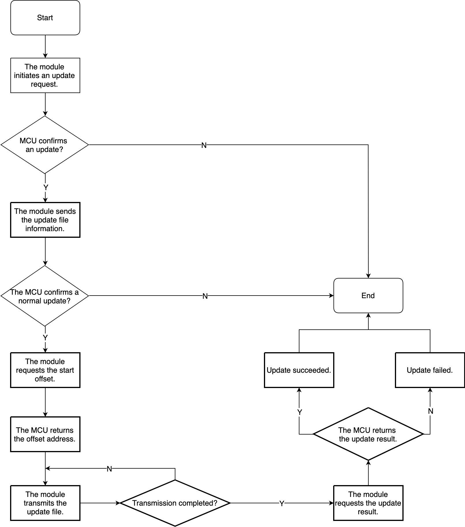
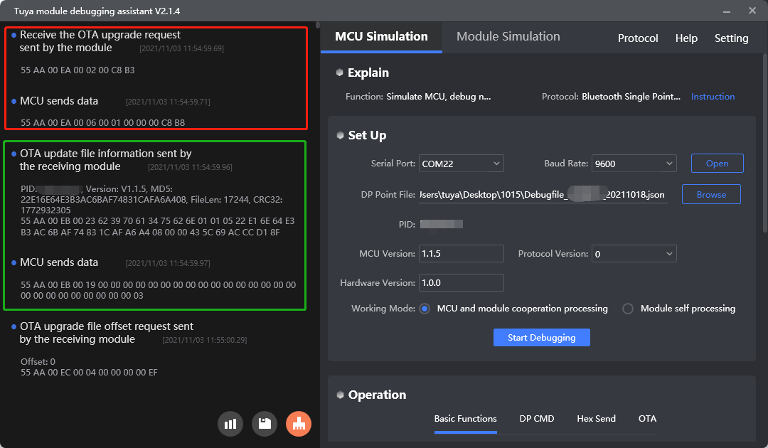
Initiate an update request (0xEA)
Purpose: The module requests the maximum transfer size of each package.
Scenario: After the user initiates an update, the module sends 0xEA to the MCU to get the transfer size of each package.
For more information, see OTA update request.
Send the update file information (0xEB)
Purpose: The module sends the update file information to the MCU, including the product ID (PID), firmware version, MD5 hash, updates size, and CRC32. The MCU returns whether or not to perform the update.
Scenario: After the module gets the transfer size with the command 0xEA, it sends the updates information through 0xEB to allow the MCU to determine whether or not to perform the update.
For more information, see Send update file information.
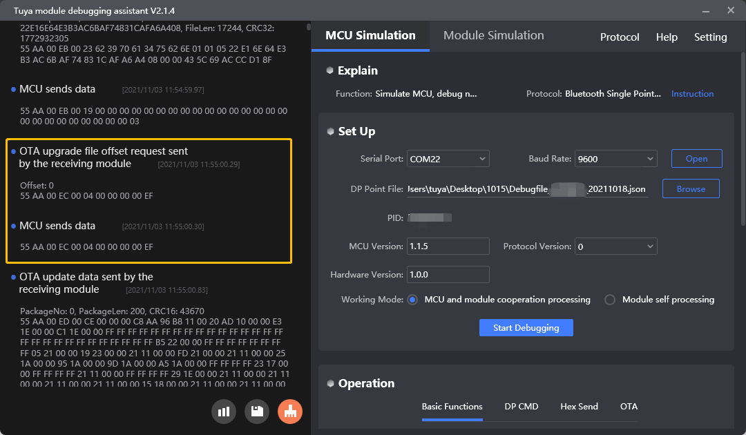
Request the update file offset (0xEC)
Purpose: The module gets the start offset.
Scenario: After the MCU confirms the update with the command 0xEB, the module requests the offset address.
For more information, see Request the offset address.
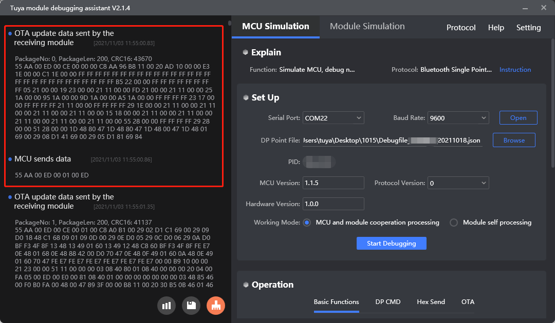
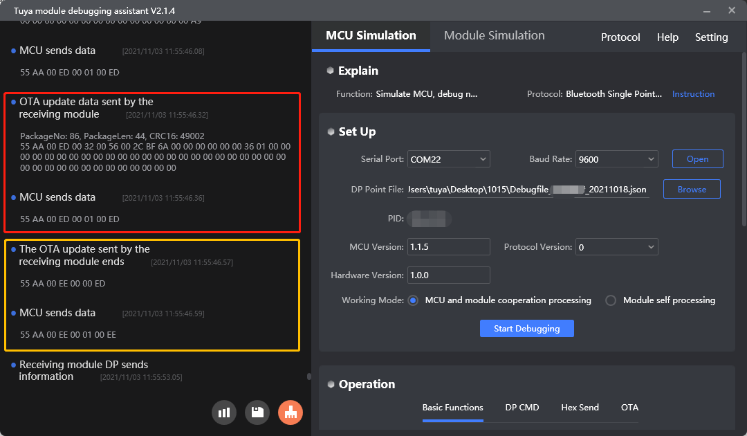
Transmit the update file (0xED)
Purpose: The module transmits the update file to the MCU.
Scenario: After the module gets the offset address, it starts transmitting the update packages to the MCU.
For more information, see Transmit the update file.
Request the update result (0xEE)
Purpose: The module gets the update result.
Scenario: The module requests the update result after the serial data transmission ends.
For more information, see Request the OTA update result.
Protocol examples
MCU SDK sample code
Initiate an update request
mcu_ota_start_req() in mcu_ota_handler.c is used for the MCU to respond to the update request with the maximum transfer size of each package.
The process is as follows:
-
Enable
SUPPORT_MCU_FIRM_UPDATEto turn on the OTA update feature. -
The MCU gets an update request from
data_handle()and callsmcu_ota_proc()to process this request. -
mcu_ota_proc()determines the request type and then callsmcu_ota_start_req()to return the update flag, the current MCU firmware version, and the maximum transfer size of each package.#define SUPPORT_MCU_FIRM_UPDATE //Enable MCU firmware upgrade (default) /* Firmware package size selection */ #ifndef SUPPORT_MCU_FIRM_UPDATE #define BT_UART_QUEUE_LMT 16 //The size of the data receiving queue can be reduced if the RAM of MCU is not enough. #define BT_UART_RECV_BUF_LMT 128 //According to the size of the user's DP data, it must be greater than 32 #else #define BT_UART_QUEUE_LMT 512 //The size of the data receiving queue can be reduced if the RAM of MCU is not enough. #define BT_UART_RECV_BUF_LMT 256 //Firmware upgrade buffer, large cache required, must be greater than 260 #endifvoid data_handle(unsigned short offset) { ...... #ifdef SUPPORT_MCU_FIRM_UPDATE case TUYA_BCI_UART_COMMON_MCU_OTA_REQUEST: case TUYA_BCI_UART_COMMON_MCU_OTA_FILE_INFO: case TUYA_BCI_UART_COMMON_MCU_OTA_FILE_OFFSET: case TUYA_BCI_UART_COMMON_MCU_OTA_DATA: case TUYA_BCI_UART_COMMON_MCU_OTA_END: total_len = bt_uart_rx_buf[offset + LENGTH_HIGH] * 0x100; total_len += bt_uart_rx_buf[offset + LENGTH_LOW]; mcu_ota_proc(cmd_type,&bt_uart_rx_buf[offset + DATA_START],total_len); break; #endif ...... }void mcu_ota_proc(uint16_t cmd,uint8_t*recv_data,uint32_t recv_len) { …… case TUYA_BCI_UART_COMMON_MCU_OTA_REQUEST: mcu_ota_start_req(recv_data,recv_len); break; …… }static void mcu_ota_start_req(uint8_t*recv_data,uint32_t recv_len) { uint8_t p_buf[12]; uint8_t payload_len = 0; uint32_t current_version = MCU_OTA_VERSION; uint16_t length = 0; if(mcu_ota_status_get()!=MCU_OTA_STATUS_NONE) { TUYA_OTA_LOG("current ota status is not MCU_OTA_STATUS_NONE and is : %d !",mcu_ota_status_get()); return; } p_buf[0] = MCU_OTA_TYPE; p_buf[1] = (current_version>>16)&0xff; p_buf[2] = (current_version>>8)&0xff; p_buf[3] = current_version&0xff; p_buf[4] = MAX_DFU_DATA_LEN>>8; p_buf[5] = MAX_DFU_DATA_LEN; mcu_ota_status_set(MCU_OTA_STATUS_START); payload_len = 6; length = set_bt_uart_buffer(length,(unsigned char *)p_buf,payload_len); bt_uart_write_frame(TUYA_BCI_UART_COMMON_MCU_OTA_REQUEST,length); }
Send the update file information
mcu_ota_file_info_req() in mcu_ota_handler.c is used for the MCU to respond to the command 0xEB with its verification result.
The process is as follows:
-
Enable
SUPPORT_MCU_FIRM_UPDATEto turn on the OTA update feature. -
The MCU gets the update file information from
data_handle()and callsmcu_ota_proc()to process this request. -
mcu_ota_proc()determines the request type and then callsmcu_ota_file_info_req()to return its verification result of the update information.void data_handle(unsigned short offset) { ...... #ifdef SUPPORT_MCU_FIRM_UPDATE case TUYA_BCI_UART_COMMON_MCU_OTA_REQUEST: case TUYA_BCI_UART_COMMON_MCU_OTA_FILE_INFO: case TUYA_BCI_UART_COMMON_MCU_OTA_FILE_OFFSET: case TUYA_BCI_UART_COMMON_MCU_OTA_DATA: case TUYA_BCI_UART_COMMON_MCU_OTA_END: total_len = bt_uart_rx_buf[offset + LENGTH_HIGH] * 0x100; total_len += bt_uart_rx_buf[offset + LENGTH_LOW]; mcu_ota_proc(cmd_type,&bt_uart_rx_buf[offset + DATA_START],total_len); break; #endif ...... }void mcu_ota_proc(uint16_t cmd,uint8_t*recv_data,uint32_t recv_len) { …… case TUYA_BCI_UART_COMMON_MCU_OTA_FILE_INFO: mcu_ota_file_info_req(recv_data,recv_len); break; …… }static void mcu_ota_file_info_req(uint8_t*recv_data,uint32_t recv_len) { uint8_t p_buf[30]; uint8_t payload_len = 0; uint32_t file_version; uint32_t file_length; uint32_t file_crc; uint8_t file_md5; // uint8_t file_md5[16]; uint16_t length = 0; uint8_t state; if(mcu_ota_status_get()!=MCU_OTA_STATUS_START) { TUYA_OTA_LOG("current ota status is not MCU_OTA_STATUS_START and is : %d !",mcu_ota_status_get()); return; } file_version = recv_data[0+8]<<16; file_version += recv_data[1+8]<<8; file_version += recv_data[2+8]; if(memcmp(s_dfu_settings.progress.firmware_file_md5,&recv_data[3+8],16)==0) { file_md5 = TRUE; } else { file_md5 = FALSE; } file_length = recv_data[27]<<24; file_length += recv_data[28]<<16; file_length += recv_data[29]<<8; file_length += recv_data[30]; file_crc = recv_data[31]<<24; file_crc += recv_data[32]<<16; file_crc += recv_data[33]<<8; file_crc += recv_data[34]; if (memcmp(&recv_data[0], PRODUCT_KEY, 8) == 0) { if((file_version > MCU_OTA_VERSION)&&(file_length <= APP_NEW_FW_MAX_SIZE)) { if(file_md5&&(s_dfu_settings.progress.firmware_file_version==file_version)&&(s_dfu_settings.progress.firmware_file_length==file_length) &&(s_dfu_settings.progress.firmware_file_crc==file_crc)) { state = 0; } else { memset(&s_dfu_settings.progress, 0, sizeof(dfu_progress_t)); s_dfu_settings.progress.firmware_image_crc_last = 0; s_dfu_settings.progress.firmware_file_version = file_version; s_dfu_settings.progress.firmware_file_length = file_length; s_dfu_settings.progress.firmware_file_crc = file_crc; memcpy(s_dfu_settings.progress.firmware_file_md5,&recv_data[3+8],16); s_dfu_settings.write_offset = s_dfu_settings.progress.firmware_image_offset_last; state = 0; mcu_flash_write(DFU_SETTING_SAVE_ADDR,(uint8_t*)&s_dfu_settings,sizeof(s_dfu_settings)); } m_firmware_start_addr = APP_NEW_FW_START_ADR; m_firmware_size_req = s_dfu_settings.progress.firmware_file_length; } else { if(file_version <= MCU_OTA_VERSION) { TUYA_OTA_LOG("ota file version error !"); state = 2; } else { TUYA_OTA_LOG("ota file length is bigger than rev space !"); state = 3; } } } else { TUYA_OTA_LOG("ota pid error !"); state = 1; } memset(p_buf,0,sizeof(p_buf)); p_buf[0] = state; if(state==0) { uint32_t crc_temp = 0; if(file_crc_check_in_flash(s_dfu_settings.progress.firmware_image_offset_last,&crc_temp)==0) { if(crc_temp != s_dfu_settings.progress.firmware_image_crc_last) { s_dfu_settings.progress.firmware_image_offset_last = 0; s_dfu_settings.progress.firmware_image_crc_last = 0; s_dfu_settings.write_offset = s_dfu_settings.progress.firmware_image_offset_last; mcu_flash_write(DFU_SETTING_SAVE_ADDR,(uint8_t*)&s_dfu_settings,sizeof(s_dfu_settings)); } } p_buf[1] = s_dfu_settings.progress.firmware_image_offset_last>>24; p_buf[2] = s_dfu_settings.progress.firmware_image_offset_last>>16; p_buf[3] = s_dfu_settings.progress.firmware_image_offset_last>>8; p_buf[4] = (uint8_t)s_dfu_settings.progress.firmware_image_offset_last; p_buf[5] = s_dfu_settings.progress.firmware_image_crc_last>>24; p_buf[6] = s_dfu_settings.progress.firmware_image_crc_last>>16; p_buf[7] = s_dfu_settings.progress.firmware_image_crc_last>>8; p_buf[8] = (uint8_t)s_dfu_settings.progress.firmware_image_crc_last; mcu_ota_status_set(MCU_OTA_STATUS_FILE_INFO); current_package = 0; last_package = 0; TUYA_OTA_LOG("ota file length : 0x%04x",s_dfu_settings.progress.firmware_file_length); TUYA_OTA_LOG("ota file crc : 0x%04x",s_dfu_settings.progress.firmware_file_crc); TUYA_OTA_LOG("ota file version : 0x%04x",s_dfu_settings.progress.firmware_file_version); TUYA_OTA_LOG("ota firmware_image_offset_last : 0x%04x",s_dfu_settings.progress.firmware_image_offset_last); TUYA_OTA_LOG("ota firmware_image_crc_last : 0x%04x",s_dfu_settings.progress.firmware_image_crc_last); TUYA_OTA_LOG("ota firmware write offset : 0x%04x",s_dfu_settings.write_offset); } payload_len = 25; length = set_bt_uart_buffer(length,(unsigned char *)p_buf,payload_len); bt_uart_write_frame(TUYA_BCI_UART_COMMON_MCU_OTA_FILE_INFO,length); }
Request the update file offset
mcu_ota_offset_req() in mcu_ota_handler.c is used for the MCU to respond to the offset request with the start offset address.
The process is as follows:
-
Enable
SUPPORT_MCU_FIRM_UPDATEto turn on the OTA update feature. -
The MCU gets the offset address request from
data_handle()and callsmcu_ota_proc()to process this request. -
mcu_ota_proc()determines the request type and then callsmcu_ota_offset_req()to return the start offset address.void data_handle(unsigned short offset) { ...... #ifdef SUPPORT_MCU_FIRM_UPDATE case TUYA_BCI_UART_COMMON_MCU_OTA_REQUEST: case TUYA_BCI_UART_COMMON_MCU_OTA_FILE_INFO: case TUYA_BCI_UART_COMMON_MCU_OTA_FILE_OFFSET: case TUYA_BCI_UART_COMMON_MCU_OTA_DATA: case TUYA_BCI_UART_COMMON_MCU_OTA_END: total_len = bt_uart_rx_buf[offset + LENGTH_HIGH] * 0x100; total_len += bt_uart_rx_buf[offset + LENGTH_LOW]; mcu_ota_proc(cmd_type,&bt_uart_rx_buf[offset + DATA_START],total_len); break; #endif ...... }void mcu_ota_proc(uint16_t cmd,uint8_t*recv_data,uint32_t recv_len) { …… case TUYA_BCI_UART_COMMON_MCU_OTA_FILE_OFFSET: mcu_ota_offset_req(recv_data,recv_len); break; …… }static void mcu_ota_offset_req(uint8_t*recv_data,uint32_t recv_len) { uint8_t p_buf[5]; uint8_t payload_len = 0; uint32_t offset; uint16_t length = 0; if(mcu_ota_status_get()!=MCU_OTA_STATUS_FILE_INFO) { TUYA_OTA_LOG("current ota status is not MCU_OTA_STATUS_FILE_INFO and is : %d !",mcu_ota_status_get()); return; } offset = recv_data[0]<<24; offset += recv_data[1]<<16; offset += recv_data[2]<<8; offset += recv_data[3]; if((offset==0)&&(s_dfu_settings.progress.firmware_image_offset_last!=0)) { s_dfu_settings.progress.firmware_image_crc_last = 0; s_dfu_settings.progress.firmware_image_offset_last = 0; s_dfu_settings.write_offset = s_dfu_settings.progress.firmware_image_offset_last; mcu_flash_write(DFU_SETTING_SAVE_ADDR,(uint8_t*)&s_dfu_settings,sizeof(s_dfu_settings)); } p_buf[0] = s_dfu_settings.progress.firmware_image_offset_last>>24; p_buf[1] = s_dfu_settings.progress.firmware_image_offset_last>>16; p_buf[2] = s_dfu_settings.progress.firmware_image_offset_last>>8; p_buf[3] = (uint8_t)s_dfu_settings.progress.firmware_image_offset_last; mcu_ota_status_set(MCU_OTA_STATUS_FILE_OFFSET); payload_len = 4; length = set_bt_uart_buffer(length,(unsigned char *)p_buf,payload_len); bt_uart_write_frame(TUYA_BCI_UART_COMMON_MCU_OTA_FILE_OFFSET,length); }
Transmit the update file
mcu_ota_data_req() in mcu_ota_handler.c is used for the MCU to return the file reception result.
The process is as follows:
-
Enable
SUPPORT_MCU_FIRM_UPDATEto turn on the OTA update feature. -
The MCU receives the update package from
data_handle()and callsmcu_ota_proc()to process this request. -
mcu_ota_proc()determines the request type and then callsmcu_ota_data_req()to return the file reception result.void data_handle(unsigned short offset) { ...... #ifdef SUPPORT_MCU_FIRM_UPDATE case TUYA_BCI_UART_COMMON_MCU_OTA_REQUEST: case TUYA_BCI_UART_COMMON_MCU_OTA_FILE_INFO: case TUYA_BCI_UART_COMMON_MCU_OTA_FILE_OFFSET: case TUYA_BCI_UART_COMMON_MCU_OTA_DATA: case TUYA_BCI_UART_COMMON_MCU_OTA_END: total_len = bt_uart_rx_buf[offset + LENGTH_HIGH] * 0x100; total_len += bt_uart_rx_buf[offset + LENGTH_LOW]; mcu_ota_proc(cmd_type,&bt_uart_rx_buf[offset + DATA_START],total_len); break; #endif ...... }void mcu_ota_proc(uint16_t cmd,uint8_t*recv_data,uint32_t recv_len) { …… case TUYA_BCI_UART_COMMON_MCU_OTA_DATA: mcu_ota_data_req(recv_data,recv_len); break; …… }static void mcu_ota_data_req(uint8_t*recv_data,uint32_t recv_len) { TUYA_OTA_LOG("%s",__func__); uint8_t p_buf[2]; uint8_t payload_len = 0; uint8_t state = 0; uint16_t len; uint8_t p_balloc_buf[256]; uint16_t length = 0; if((mcu_ota_status_get()!=MCU_OTA_STATUS_FILE_OFFSET)&&(mcu_ota_status_get()!=MCU_OTA_STATUS_FILE_DATA)) { TUYA_OTA_LOG("current ota status is not MCU_OTA_STATUS_FILE_OFFSET or MCU_OTA_STATUS_FILE_DATA and is : %d !",mcu_ota_status_get()); return; } state = 0; current_package = (recv_data[0]<<8)|recv_data[1]; len = (recv_data[2]<<8)|recv_data[3]; if((current_package!=(last_package+1))&&(current_package!=0)) { TUYA_OTA_LOG("ota received package number error.received package number : %d",current_package); state = 1; } else if(len>MAX_DFU_DATA_LEN) { TUYA_OTA_LOG("ota received package data length error : %d",len); state = 5; } else { uint32_t const write_addr = APP_NEW_FW_START_ADR + s_dfu_settings.write_offset; if(write_addr>=APP_NEW_FW_END_ADR) { TUYA_OTA_LOG("ota write addr error."); state = 1; } if(write_addr%CODE_PAGE_SIZE==0) { if (mcu_flash_erase(write_addr,4096)!= 0) { TUYA_OTA_LOG("ota Erase page operation failed"); state = 4; } } if(state==0) { len = (recv_data[2]<<8)|recv_data[3]; memcpy(p_balloc_buf, &recv_data[6], len); uint8_t ret = mcu_flash_write(write_addr, p_balloc_buf, len); TUYA_OTA_LOG("ota save len :%d",len); if (ret != 0) { state = 4; } else { s_dfu_settings.progress.firmware_image_crc_last = crc32_compute(p_balloc_buf, len, &s_dfu_settings.progress.firmware_image_crc_last); s_dfu_settings.write_offset += len; s_dfu_settings.progress.firmware_image_offset_last += len; if((current_package+1)%32==0) { mcu_flash_write(DFU_SETTING_SAVE_ADDR,(uint8_t*)&s_dfu_settings,sizeof(s_dfu_settings)); } } } } p_buf[0] = state; mcu_ota_status_set(MCU_OTA_STATUS_FILE_DATA); payload_len = 1; length = set_bt_uart_buffer(length,(unsigned char *)p_buf,payload_len); bt_uart_write_frame(TUYA_BCI_UART_COMMON_MCU_OTA_DATA,length); if(state!=0) { TUYA_OTA_LOG("ota error so free!"); mcu_ota_status_set(MCU_OTA_STATUS_NONE); mcu_ota_init_disconnect(); memset(&s_dfu_settings, 0, sizeof(dfu_settings_t)); mcu_flash_write(DFU_SETTING_SAVE_ADDR,(uint8_t*)&s_dfu_settings,sizeof(s_dfu_settings)); } else { last_package = current_package; } }
Request the update result
mcu_ota_end_req() in mcu_ota_handler.c is used for the MCU to return the update result.
The process is as follows:
-
Enable
SUPPORT_MCU_FIRM_UPDATEto turn on the OTA update feature. -
The MCU gets the update result request from
data_handle()and callsmcu_ota_proc()to process this request. -
mcu_ota_proc()determines the request type and then callsmcu_ota_end_req()to return the update result.void data_handle(unsigned short offset) { ...... #ifdef SUPPORT_MCU_FIRM_UPDATE case TUYA_BCI_UART_COMMON_MCU_OTA_REQUEST: case TUYA_BCI_UART_COMMON_MCU_OTA_FILE_INFO: case TUYA_BCI_UART_COMMON_MCU_OTA_FILE_OFFSET: case TUYA_BCI_UART_COMMON_MCU_OTA_DATA: case TUYA_BCI_UART_COMMON_MCU_OTA_END: total_len = bt_uart_rx_buf[offset + LENGTH_HIGH] * 0x100; total_len += bt_uart_rx_buf[offset + LENGTH_LOW]; mcu_ota_proc(cmd_type,&bt_uart_rx_buf[offset + DATA_START],total_len); break; #endif ...... }void mcu_ota_proc(uint16_t cmd,uint8_t*recv_data,uint32_t recv_len) { …… case TUYA_BCI_UART_COMMON_MCU_OTA_END: mcu_ota_end_req(recv_data,recv_len); break; …… }static void mcu_ota_end_req(uint8_t*recv_data,uint32_t recv_len) { if(mcu_ota_status_get()==MCU_OTA_STATUS_NONE) { TUYA_OTA_LOG("current ota status is MCU_OTA_STATUS_NONE!"); return; } on_data_write_request_sched(NULL); }
Production test
How it works
The protocol provides the commands used for radio frequency (RF) testing.
Scenarios
After you have tested the basic features, you can perform the RF testing separately or integrate it into the end product test to verify the wireless connectivity performance. You can define how a test is triggered as needed.
Commands
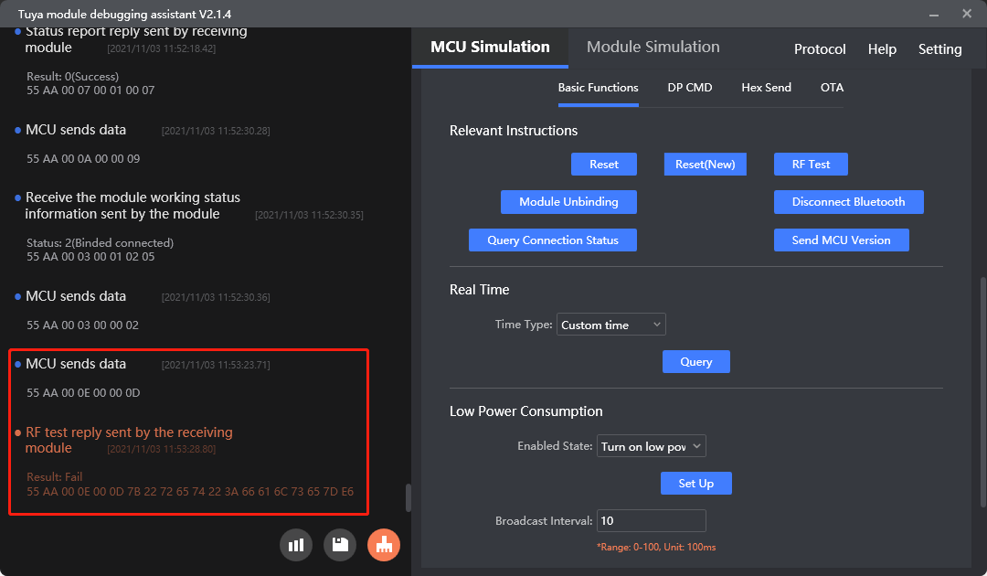
Initiate an RF test (0x0E)
The module scans for the designated Bluetooth beacon ty_mdev and returns signal strength in percentage on successful scanning.
Scenario: Prepare a Bluetooth beacon and set its identifier to ty_mdev. It is recommended that the distance between the router and the device under test should be about 0.5 meters. The MCU sends this command to the module to initiate a test. The module will scan for the designated identifier and return the RSSI. If the RSSI is greater than -70 dB, the RF performance is acceptable.
The BK3431Q and BK3432 do not support scanning for a designated beacon. You need to perform an RF test with a dongle.
- Test tool:
- A Bluetooth dongle provided by Tuya.
- The dongle can return the RSSI result.
- Test steps: Put the dongle around 0.5 meters away from the module. The MCU sends this command to the module to initiate a test. The dongle will connect to the module and return the RSSI. If the RSSI is greater than -70 dB, the RF performance is acceptable.
Protocol examples
RF testing
MCU SDK sample code
RF testing
bt_rf_test_req() in protocol.c is used for the MCU to send the command 0x0E to the module for initiating an RF test.
The process is as follows:
-
Enable
TUYA_BCI_UART_COMMON_RF_TESTto turn on the RF testing. -
The MCU calls
bt_rf_test_req()to send0x0Eto the module for initiating an RF test. -
The MCU gets the test result from
data_handle()and callsbt_rf_test_result()to proceed with the next operation. The implementation ofbt_rf_test_result()is intended to be performed by you.#define TUYA_BCI_UART_COMMON_RF_TEST 0x0E //rf radio frequency test/***************************************************************************** Function name: bt_rf_test_req Function description: transmit frequency test request to the module Input parameters: None Return parameter: none Instructions for use: *****************************************************************************/ void bt_rf_test_req(void) { bt_uart_write_frame(TUYA_BCI_UART_COMMON_RF_TEST,0); }void data_handle(unsigned short offset) { ...... #ifdef TUYA_BCI_UART_COMMON_RF_TEST case TUYA_BCI_UART_COMMON_RF_TEST: if(my_memcmp((unsigned char *)bt_uart_rx_buf + offset + DATA_START+7,"true",4)==0) { bt_rssi = (bt_uart_rx_buf[offset + DATA_START+21]-'0')*10 + (bt_uart_rx_buf[offset + DATA_START+22]-'0'); bt_rssi = -bt_rssi; bt_rf_test_result(1,bt_rssi); } else { bt_rf_test_result(0,0); } break; #endif ...... }/***************************************************************************** Function name: bt_rf_test_result Function description: Bluetooth RF test feedback Input parameter: Result: Bluetooth RF test result;0: failure /1: success Rssi: Successful test indicates that the Bluetooth signal strength/test failure value is meaningless Return parameter: none Instructions: The MCU needs to improve the function itself *****************************************************************************/ void bt_rf_test_result(unsigned char result,signed char rssi) { #error "Please improve the function by yourself and delete the line after completion" if(result == 0) { // The test failed } else { // The test was successful // RSSI is the signal strength, which is generally greater than -70dbM and within the normal range of Bluetooth signals } }
Request the work status of the module
How it works
The MCU sends this command to proactively get the current work status of the module.
Scenarios
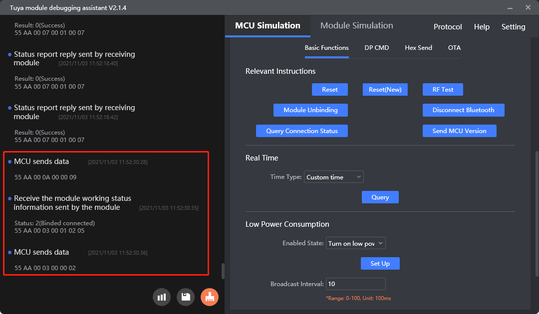
The module proactively sends its current work status to the MCU through 0x03 only when it detects a restart or reconnection. The MCU can send this command to the module to proactively request the current work status of the module.
Commands
Request the work status of the module (0x0A)
Purpose: The MCU proactively gets the current work status of the module. The module returns its work status through 0x03.
For more information, see Request work status.
Protocol examples
Is this page helpful?
YesFeedbackIs this page helpful?
YesFeedback


