LTE Cat.1 Integration Solution
LTE Cat.1 is a medium-speed and Voice over LTE (VoLTE)-support LTE standard designed for a low-power wide-area (LPWA) IoT network. It connects things-to-things and things-to-persons across borders.
Background information
Cat.1 stands for LTE UE Category 1. LTE uses the user equipment (UE) categories to define the performance of LTE devices. The 3rd Generation Partnership Project (3GPP) organization defines 20 different LTE UE categories. Each category has fixed parameters like data rates and bandwidth. Cat.1 provides speeds of 10 Mbit/s downlink and 5 Mbit/s uplink, ideal for feature-rich IoT applications.
Features
- Medium speed: provides a maximum of 10 Mbit/s downlink and 5 Mbit/s uplink speeds.
- Full mobility and low latency: comparable to LTE Cat.4 in terms of the low latency of less than 100 ms. Support movement speeds above 100 km/h. Address requirements for real-time transmission, perfect for IoT applications like mobile payment, mobile devices, and sharing economy.
- VoLTE: For voice-featured smart devices such as two-way radios and robot toys, Cat.1 supports voice interaction over a 4G LTE network.
- Bluetooth 4.2 Low Energy enabled: allows users to activate and control devices through a Bluetooth connection.
- Support Wi-Fi-based indoor positioning.
- Cost efficiency:
-
Network infrastructure: Cat.1 can seamlessly connect to existing LTE networks. You do not need to upgrade or create new software or hardware for base stations. Cat.1 is a cost-efficient choice to improve network coverage.
-
Hardware advantage: The use of a single antenna allows you to reduce the hardware costs compared with Cat.4 modules.
Low power consumption: The average power consumption is 5 mA over a persistent TCP connection. The minimum power consumption is 2.5 mA in the attach procedure and 1 mA in airplane mode.
-
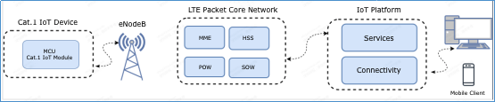
Network architecture
The Cat.1 IoT network consists of the Cat.1 smart devices, LTE base stations, LTE packet core network, Developer Platform, and service platform.
Power saving mode
When the Cat.1 smart device operates in normal mode and the CPU runs at full speed, the power consumption is about 30 mA. In power saving mode, the device can stay either in light sleep mode or deep sleep mode.
-
In light sleep mode: The CPU enters a low-power standby state and the hardware automatically changes the clock to 26 MHz. The power consumption is around 15 mA.
-
In deep sleep mode: The system uses a 32 kHz crystal oscillator and DC-DC buck converter. All peripherals are powered off, such as the serial ports, Inter-Integrated Circuit (IIC), and Serial Peripheral Interface (SPI).
Working mode
-
Fully-operational mode
The device enables radio frequency (RF) communication. Network functionality, Bluetooth, phone calls, SMS messaging, and Wi-Fi positioning are supported.
-
Airplane mode
The device disables radio frequency (RF) communication. Network functionality, Bluetooth, phone calls, SMS messaging, and Wi-Fi services are unavailable.
Delay
-
Delay in initial access: When a Cat.1 device is turned on, it communicates with the cellular network for authentication, channel establishment, and IP address assignment. In varied local network environments, it takes three to eight seconds to complete networking and get an IP address for data transmission.
-
Delay in data communication: The Cat.1 device is directly connected to the Tuya Developer Platform and stays connected.
Module status DP sensitivity (millisecond) Deep sleep 500 Light sleep 150 Normal 100 Note: In deep sleep mode, when the device receives network control data, the system automatically exits the deep sleep mode and enters the normal mode.
Prerequisite for service integration
-
Cat.1 devices run over a cellular network, so the network functionality depends on carrier configuration. Therefore, make sure you selected the correct APN service when you purchase SIM cards.
-
Tuya’s Cat.1 module supports automatic APN configuration. Alternatively, you can write APN settings.
If you do not know how to select a suitable APN service, you can contact the account manager or technical support.
MCU general integration
The MCU general integration lets you connect Cat.1 smart devices to the Tuya Developer Platform. Tuya’s module only serves data transmission.
This solution applies to home appliances, security devices, sensors, personal transporters, and trackers.
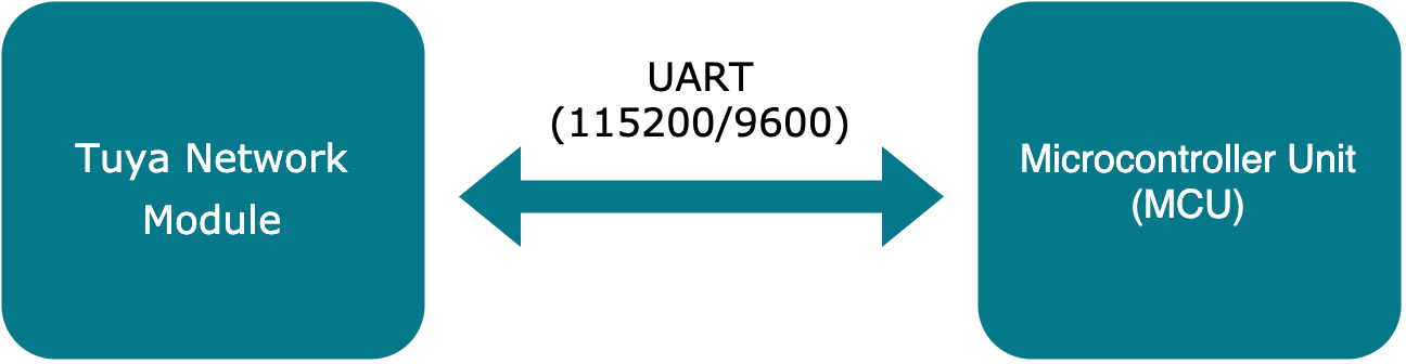
Different from the widely used attention command (AT command) development, Tuya’s open source serial protocol enables low-code development. It allows you to easily and quickly integrate with newly-launched products.
Development procedure
To develop a Cat.1 IoT product on the Tuya Developer Platform, you need to complete product creation, hardware debugging, software development, and function debugging. This section describes how to develop a product on the Tuya Developer Platform. For more information, see Create Products.
Step 1: Create product
Log in to the Tuya Developer Platform. Select the desired product. Select LTE Cat.1 for the protocol type. After you create a product, you can configure the functions, panel, module, and firmware based on your product requirements, and download the MCU development documents accordingly.
Step 2: Select network module
In the following example, the LZ201-CN LTE Cat.1 module is used. This module applies to the most cases of this solution.
After you select a module model, you can purchase the sample module on the Tuya Developer Platform. During the hardware development, you can proceed with the board layout design. For more information about hardware development, see related documents in Tuya’s documentation center.
Note: The peak current of the Cat.1 IoT module is more than 1A. The electric allowance is required in the power circuit design.
Step 3: Associate and verify module
You can use the debugging assistant to pair the module and check whether your received module can work as expected.
In MCU simulation mode, the debugging assistant simulates the MCU and returns the valid data to the module. This can help you understand interaction process over the protocol. After you associate the module with the app, you can test data point (DP) data communication.
The following steps describe how to pair the module and run the debugging assistant. For more information about the debugging assistant, see Module Debugging Assistant.
-
Follow the schematic diagram of the minimal system to build the peripheral circuit of the module with a stable power supply and excellent antenna performance. The 4G LTE IoT card must be inserted.
-
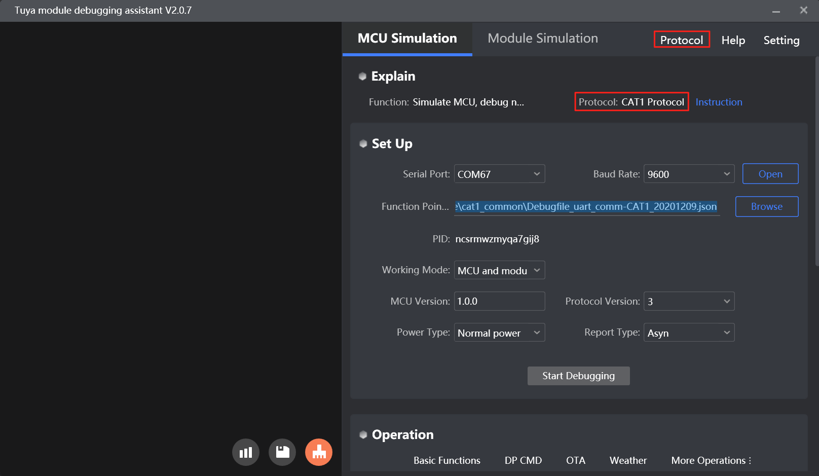
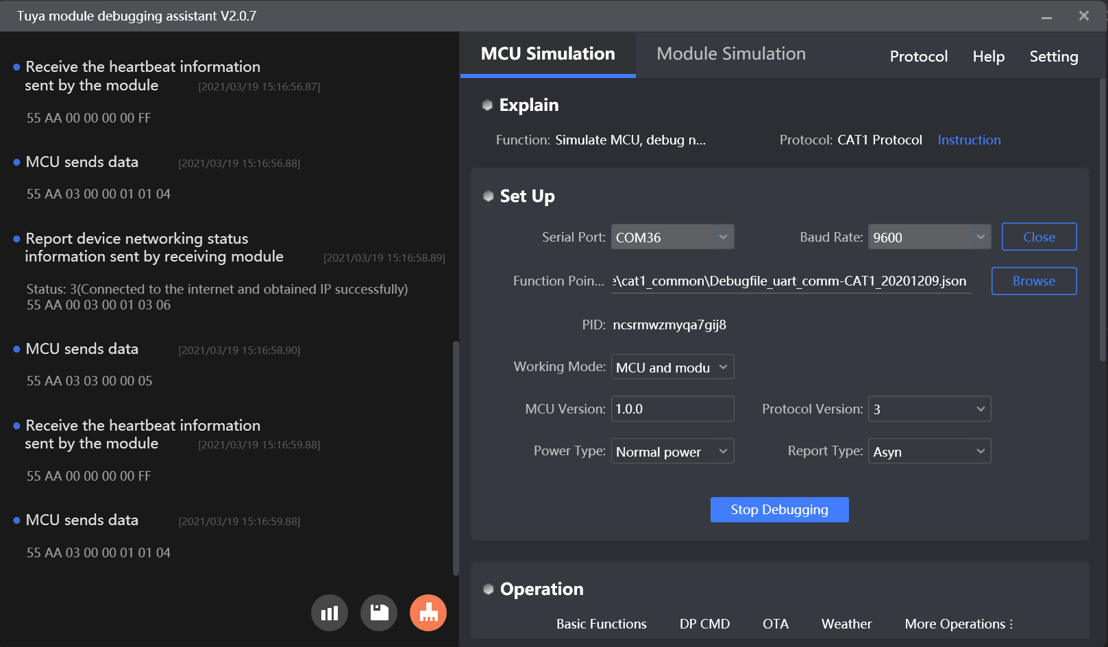
Open the debugging assistant and import the debugging file. Select the Cat.1 Protocol and MCU Simulation.
-
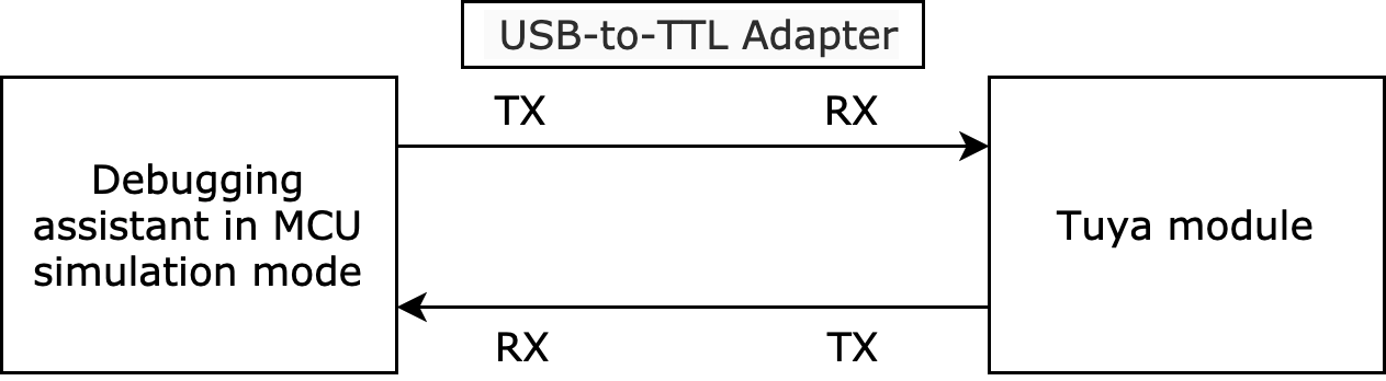
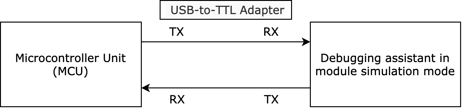
Connect the module to the computer by using a USB-to-TTL adapter. Set the serial port and baud rate in the debugging assistant. You can open the serial port and click Start Debugging to start the protocol initialization.
Note: After power-on, the Cat.1 IoT module constantly sends commands to query the product information. When valid data is returned, the module proceeds with the protocol initialization. If the module does not send data after power-on, you should check whether the peripheral circuit of the module works as expected.
-
Associate the module with the app over Bluetooth:
-
Activate the module
After the Cat.1 IoT module is powered on and initialized for the first time, it is registered on the carrier network based on the information that is read from the inserted SIM card. After the module gets the product information and working mode, it gets ready for association.
-
Bind the device
Only the activated modules that are not associated with other accounts can be associated with the app.
Enable Bluetooth on your mobile phone and open the Tuya app. Then, the app automatically scans the device pending paring.
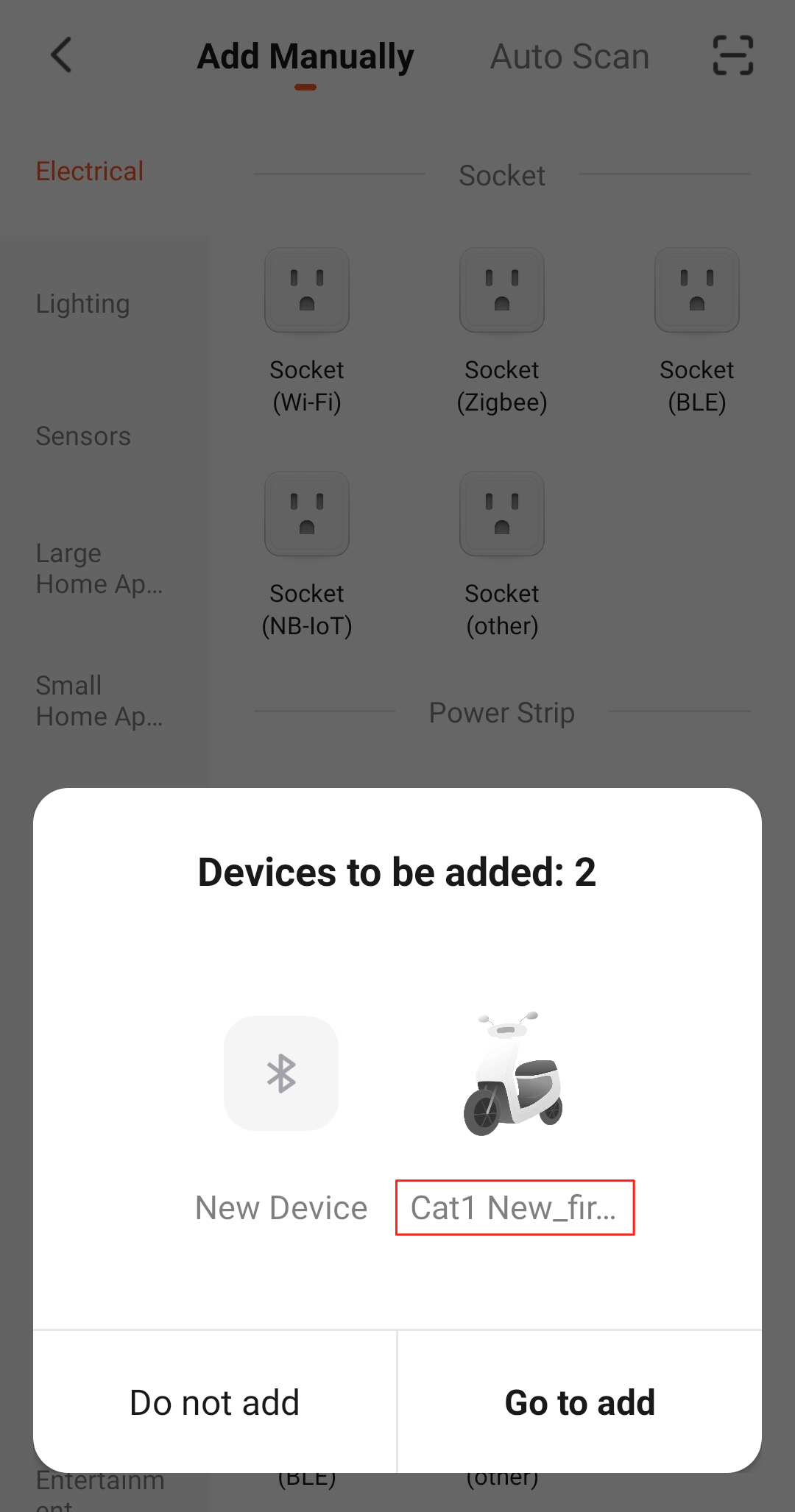
-
-
Scan the QR code to add the device:
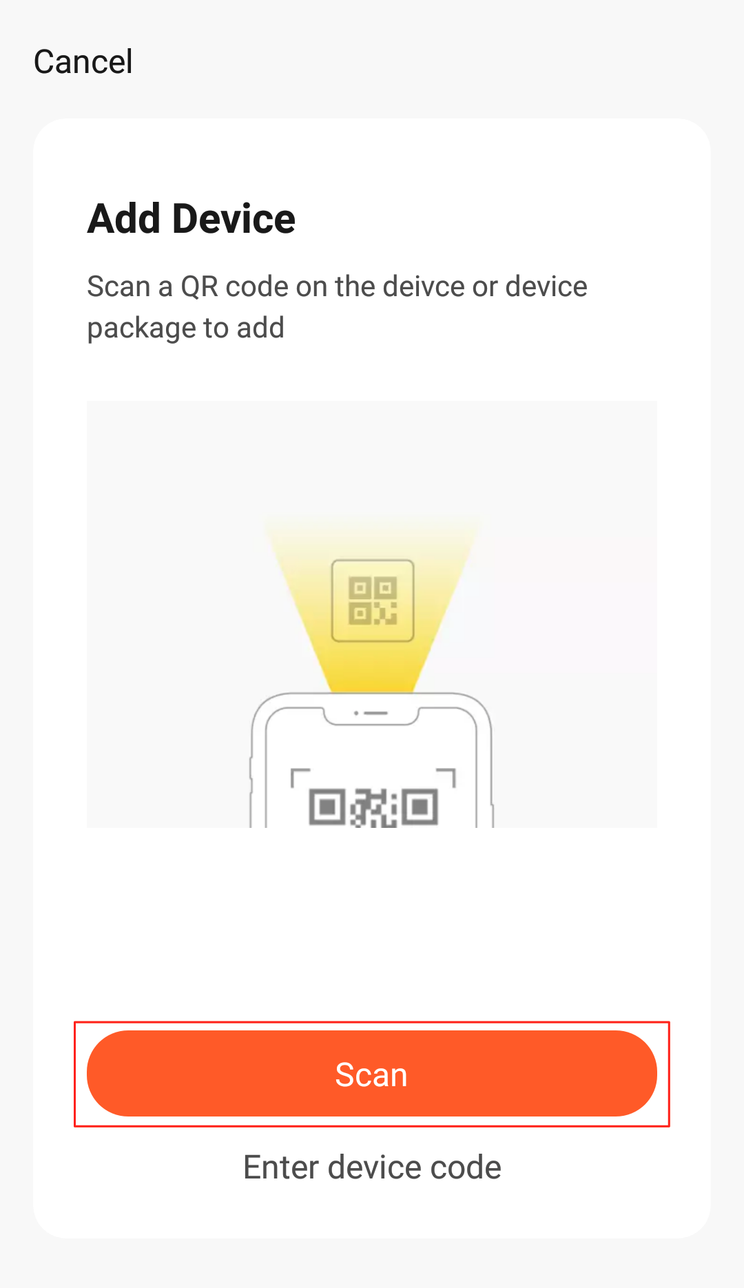
Note: The Cat.1 IoT QR code is generated by Tuya’s printing tools. For more information, contact Tuya’s account manager or request technical support.
Step 4: Develop software
In Step 3, the debugging assistant displays the serial protocol initialization. To understand the protocol details, you can view protocol documentation included in the MCU development documents. The protocol consists of the basic protocol and the function protocol.
-
The basic protocol is product-neutral and shared by the modules. It consists of commands for module initialization and extended functions. For more information, see MCU SDK Migration.
-
The function protocol works to report and send commands based on the basic protocol and specifies the DP data format.
The following serial protocol integration methods are available to support different types of MCUs.
-
Method 1: Integrate with protocol yourself
If your MCU does not have sufficient resources or not support Tuya’s MCU SDK, you can integrate with the serial protocol yourself.
-
Method 2: Port the MCU SDK
If your MCU has sufficient resources, we recommend you port the MCU SDK for efficiency purposes. The MCU SDK in the development documents is the protocol application code in C. You can import the MCU SDK to your MCU project. The MCU SDK requires the following MCU hardware resources: 4 KB flash memory and about 100 bytes of RAM. RAM depends on the DP data length. The 9-level nested function is adopted.
For more information, see MCU SDK Migration.
Step 5: Verify protocol
After you port the MCU SDK, you can use the module simulation mode in the debugging assistant to verify the code.
In module simulation mode, the debugging assistant automatically initiates the module initialization to check whether the MCU can return valid data. If an error occurs, an error message is returned. After the initialization is verified, you can test other extended functions. After that, you can pair the actual module and test device functions.
Note: The module simulation mode only verifies the serial communication and does not support networking.
Step 6: Debug functions
After the code is verified, you can pair the module with the app and test DP data communication.
During the debugging, you can access the following services to troubleshoot issues:
-
Operation: You can view backend data in the Operation center to facilitate function debugging.
-
Service & Support: If you have any problems during development, you can submit a ticket to request technical support.
OTA firmware updates
Over-the-air (OTA) firmware updates are available. For more information, see OTA Update Guide.
Is this page helpful?
YesFeedbackIs this page helpful?
YesFeedback


