Offline Voice IoT Solution
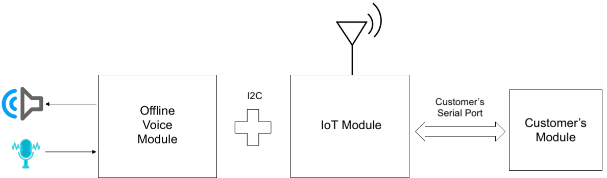
Tuya’s offline voice IoT solution combines offline voice modules and IoT modules. You can remotely control the product through offline voice and mobile app, and you can also call mobile app scenes by voice.
Tuya provides offline voice modules, IoT modules, mobile phone panel components, and offline voice IIC protocols, to provide you with fast product connection solutions.
Introduction
Offline voice module
- Support offline voice module VCT1 and VCT2
- Single microphone input
- Single speaker output
- Support Tuya Voice Service wake-up words
- Support Mandarin Chinese
- Up to 100 entries
- TTS custom reply
- 3m far-field wake-up
- Control the device functions by voice
- Call app scenes by voice
- Guide the devices by voice to enter the pairing mode
IoT module
- Support Wi-Fi + Bluetooth modules WB3S and WB2S
- Support Zigbee modules ZS3L and ZS2S
- Support Wi-Fi and Zigbee universal serial port protocol
- Support Wi-Fi and Zigbee offline voice IIC protocol
Mobile panel components
- Support adding offline voice assistants on the panel studio, and customizing the panel
- Support custom icon for offline voice assistant
- Support speaker volume adjustment
- Support panel display of offline entries
Offline voice IIC protocol
- Support transparent transmission of data points
- Support transparent transmission of scene text
- Support pairing protocol
- Support status interaction
Solution creation
Step 1: Determine the connection method
-
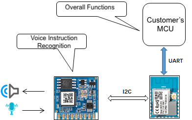
For products with complex functions that require a separate MCU to process, it is recommended to use a custom solution with MCU serial port.
-
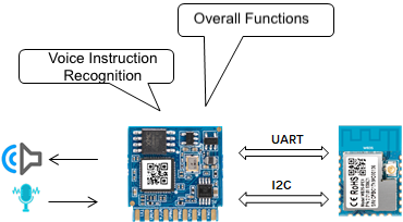
For products with simple functions that can be processed by offline voice modules directly, it is recommended to use the no-code development solution.
Step 2: Determine offline voice requirements
- Determine the functions of the product, and list the control entry text and broadcast response text.
- Determine the preset app scene text.
Step 3: Create a product
This section only describes the general product creation steps. For more information, see Create Products.
-
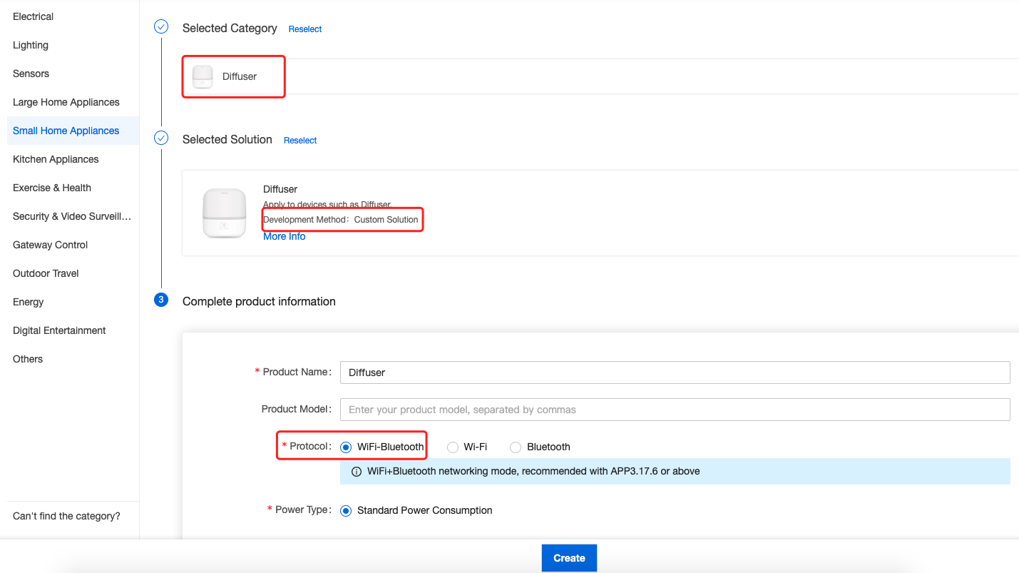
On Tuya Developer Platform, select a product.
-
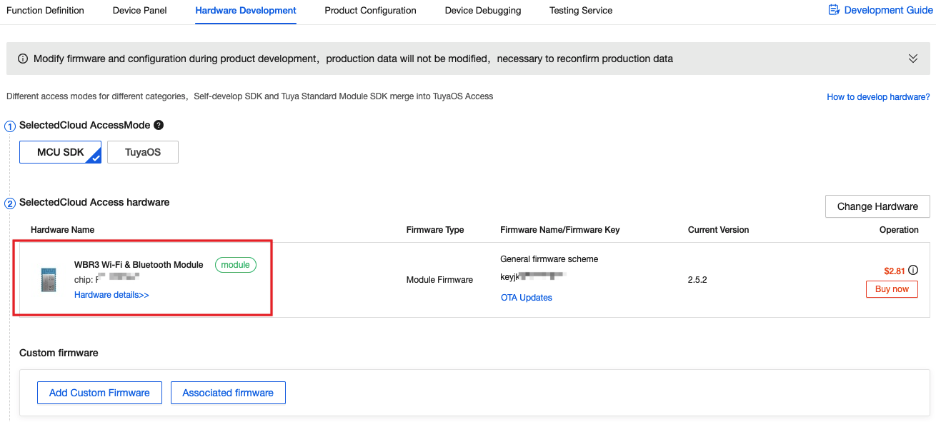
Take the Wi-Fi offline voice aroma diffuser as an example, select the aroma diffuser category, select a custom solution and Wi-Fi + Bluetooth protocol.
-
-
Contact the Tuya account manager to assist in binding the specified Wi-Fi module and firmware, and open the voice system data points 203 to 208.
-
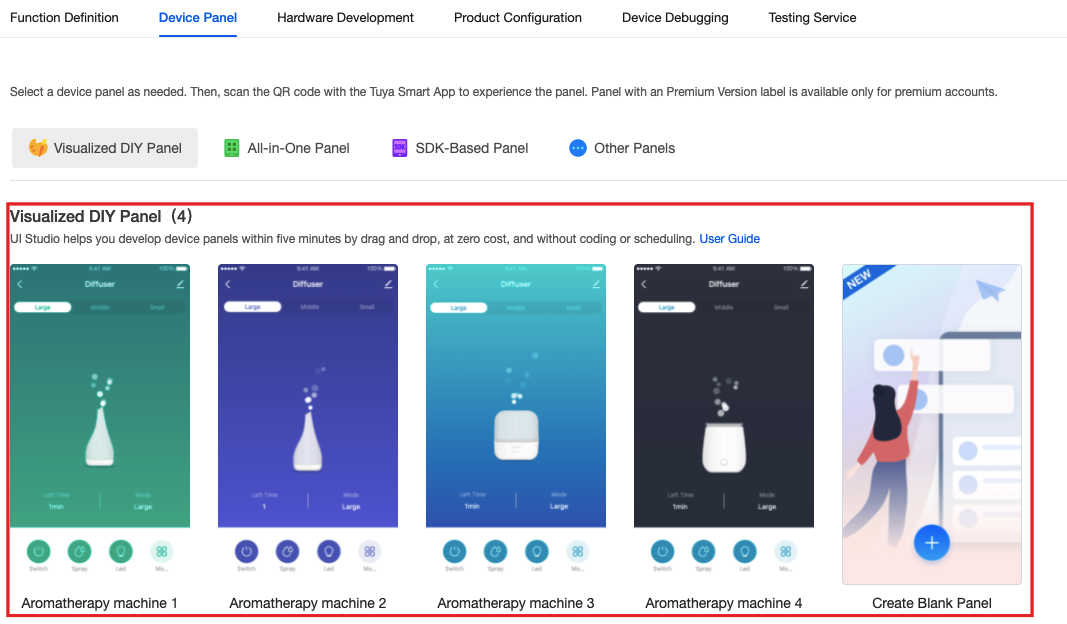
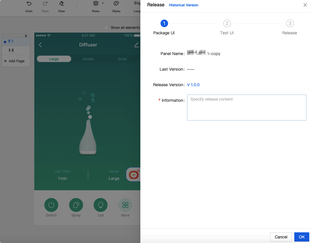
Select Visualized DIY Panel.
-
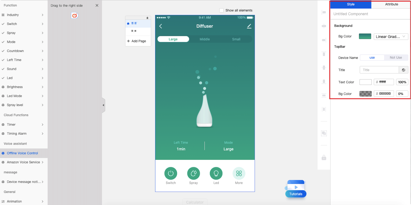
Edit the panel and choose to add an offline voice assistant.
-
You can freely adjust the initial position, icon, background, and transparency of the voice assistant.
-
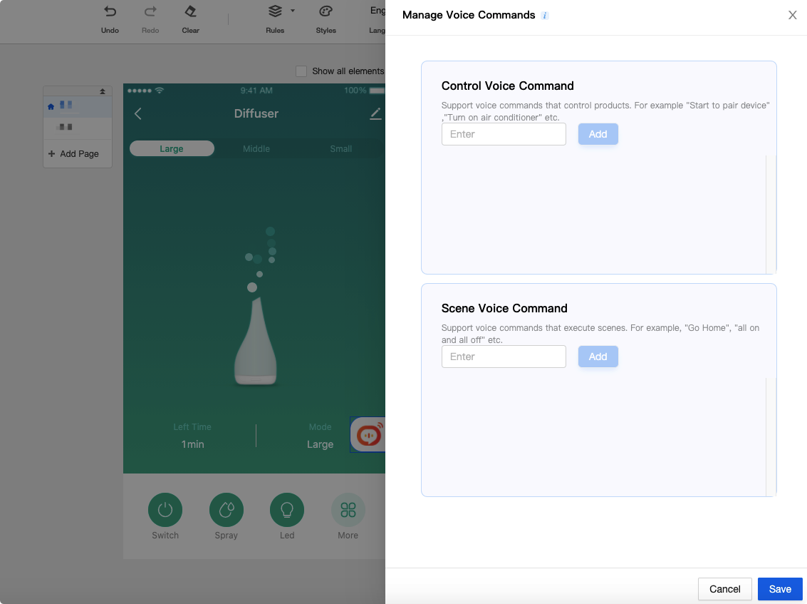
Edit the preset control text and scene text already supported by the offline voice module.
-
Complete panel editing, testing, and release.
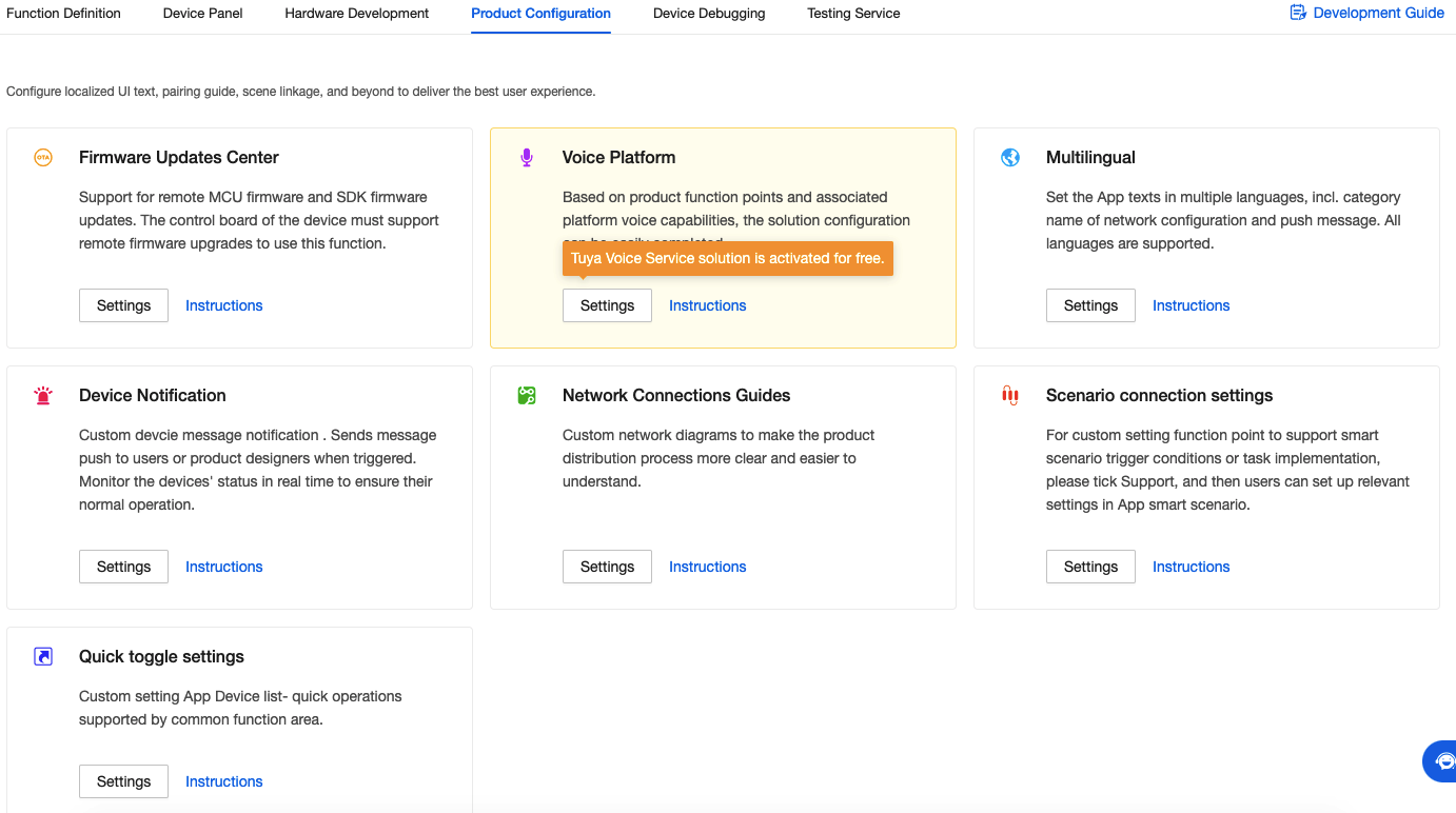
-
-
Complete product configuration such as multi-language, pairing copywriting, and third-party voice skills, and release the product.
Step 4: Product assembly and testing
- Contact Tuya account manager to obtain offline voice module and firmware.
- Complete prototype production, and test the offline voice function and IoT function of the product.
- The test is completed and the order is placed for mass production.
Schematic design reference
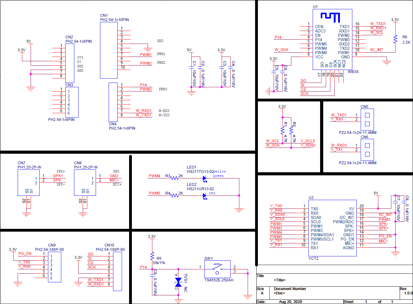
-
Schematic diagram reference of offline voice + Wi-Fi module WB3S solution
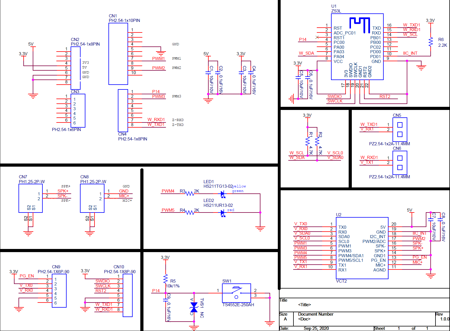
-
Schematic diagram reference of offline voice + Zigbee module ZS3L
Selection and structure design reference
Microphone selection
- Choose an analog microphone, and the sensitivity and signal-to-noise ratio of the microphone should be as high as possible. The recommended sensitivity level is -32±3dB and signal-to-noise ratio >70dB.
- The microphone needs to specify whether it needs to be waterproof and dustproof. If necessary, use a waterproof and dustproof membrane microphone with corresponding specifications.
- The thickness of the microphone sleeve, wire material, and socket interface need to be matched with the structure. The structure is designed with holes and slots according to the physical size of the microphone and the rubber sleeve.
- Since the microphone involves the rubber sleeve and structure, there may be a mold opening and order cycle. Pay attention to this point in advance.
Microphone structure design reference
-
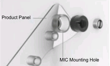
Microphone installation location selection
-
It is necessary to expand the pickup range as much as possible to avoid obstruction.
-
Place it on the front of the product to ensure maximum sound pickup. In short, the microphone needs to be reasonably designed on the front/top/bottom position of the product, and the microphone’s pickup range must be maximized.
-
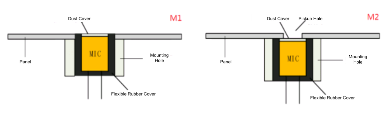
There are usually two ways to open the shell of the microphone installation position. One is that the microphone is completely exposed parallel to the product surface, and the other is that one or more small holes are opened in the microphone, and the diameter of the central opening is 1.5 to 4 mm. The relationship between the center hole diameter and the panel depth (thickness): the hole diameter is required to be >80% of the hole depth.
-
For machines where the microphone position does not vibrate during work, generally, a thin rubber sleeve is used for the microphone (the overall diameter is about 7.2 mm after the rubber sleeve is put on). For machines where the microphone position vibrates during work, it is necessary to avoid vibration to the microphone from the structure. The microphone needs to use a thick rubber sleeve (the overall diameter is about 10 mm after the rubber sleeve is put on). For machines with large vibration, the structure material of the microphone installation position needs to be changed to a soft material to achieve the vibration reduction effect (such as silicone material) .
-
-
Interference source noise reduction reference:
- The microphone should try to avoid the influence of wind and airflow. The medium of sound transmission is air. When the wind is greater than 1m/s, the air will flow, causing the medium to form a state of uneven density. In this case, the sound transmission will be distorted and affect the recognition effect.
- The microphone should be as far away as possible from the noise source. If noise is generated when the machine is working, the microphone should be installed as far away as possible from the noise source.
- The microphone and circuit should be as far away as possible from electromagnetic interference (such as motors). Note that microphones generally have positive and negative directions, and reverse connections will affect the recognition effect.
-
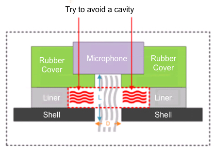
Mounting hole design:
-
Make a cavity to fix the microphone and keep it sealed, so that there can be no air convection in the gap between the microphone and the shell.
-
Mounting hole fixing: After the microphone is installed in the cavity, the back of the microphone needs to be fixed (see installation instructions below). Strictly avoid the vibration, sound source, airflow, and other noise inside the structure from being directly transmitted to the microphone.
-
If the product is designed with AEC (interrupt function), you need to pay special attention to separate the speaker from the microphone and try to avoid the sound from the speaker directly entering the microphone at close range.
-
-
When installing the microphone, it must be fully inserted into the rubber sleeve, and the seal must be kept tight. Avoid skewed installation and the microphone is not inserted into the bottom of the rubber sleeve.
-
Other design considerations:
-
Design the structure of the mounting hole according to the size of the actual microphone.
-
Pay attention to the hole diameter and depth of the pickup hole. The hole diameter is required to be >80% of the hole depth.
-
The center of the pickup hole and the center of the microphone should be aligned.
-
The distance between the center of the pickup hole and the edge of the panel is >1 cm.
-
If the microphone opening inevitably leaves a gap, please ensure that the gap is symmetrical. If the gap on a certain side of the microphone is too large, it will seriously affect the microphone’s sound collection and voice recognition effect.
-
-
After the microphone is correctly installed in the mounting hole, it is recommended to seal the back of the microphone with a rubber pad and fix it with plastic to ensure that the back of the microphone is tightly sealed and firm. This can prevent the sound (or noise) from the back of the microphone (or within the product structure) from entering the inside of the microphone through the back of the microphone and affecting the recognition effect.
-
Through the rubber cover, gasket, and fixing device, the influence of the sound from the directions other than the front of the microphone can be greatly reduced, and the effective sound can be transmitted from the front of the microphone as much as possible, thereby ensuring the recognition effect.
-
It is strictly forbidden to use sharp tools to touch or hold the front of the microphone to remove it, or to grab the microphone cable with bare hands and pull it hard. After disassembling the microphone headband and rubber cover assembly, it is recommended to replace the assembly as a whole to avoid improper disassembly and affect the microphone quality.
-
The microphone should avoid manual soldering of the microphone pad. Manual soldering will affect the performance of important indicators of the microphone (such as sensitivity and SNR).
-
It is recommended to use a sealing material to seal the back of the microphone to prevent sound waves from the back of the microphone from entering the microphone and affecting the recognition effect.
-
If you consider the cost factor and use glue to seal the back of the microphone, you need to pay attention to the working environment to avoid high temperatures and pay attention to the quality of the hot melt glue stick. Our company recommends using high-quality hot-melt glue sticks to avoid premature cracking or falling off of the glue.
Speaker selection
- The basic specification of the power amplifier is 8 ohms 2W. Without changing the power amplifier, please choose 8 ohms 2W and below 2W speakers. If the customer chooses the power amplifier, the customer chooses the speaker power by themselves.
- The size of the speaker is properly selected according to the product structure.
Speaker structure design reference
- The speaker should be as far away from the microphone as possible, and put behind the microphone.
- When designing the product structure, it is necessary to consider and handle the sound transmission and vibration transmission when the speaker is playing. Avoid or reduce the speaker sound to the microphone, and take measures to avoid or reduce vibration.
- If the speaker sound enters the microphone too much, it will affect the voice recognition effect (depending on the specific product, specific structure, and specific application scenarios).
- When designing the product structure, it is recommended to design the sound hole and installation groove of the speaker to prevent the speaker sound from being reflected and transmitted inside the product structure and affecting the recognition effect.
- The sound of the speaker should not be transmitted directly in the product structure as much as possible, and should be transmitted to the outside of the product through the sound hole as much as possible. It can be avoided by adding sealing material around the speaker cone. Open a special installation groove and seal the back of the speaker.
- Considering product appearance, structure, and safety factors, it is recommended to open multiple 1–3 mm small holes as sound holes in the projection area in the direction of the speaker cone.
Is this page helpful?
YesFeedbackIs this page helpful?
YesFeedback


