Quick Start
This topic shows you how to try out product development by editing the demo.
With this demo, you can implement:
- Pressing and holding the S2 (
TY_GPIOA_9) button on the CBU Nano board can reset the device to make it enter pairing mode. - Pressing the S2 button can control the onboard LED indicator D2 (
TY_GPIOA_16).
Preparation
-
Hardware:
-
A CBU Nano development board. Other Tuya’s Wi-Fi modules or development boards also work.
-
A micro-USB cable.
If your hardware does not have a built-in USB to TTL transfer chip, prepare at least one USB to TTL converter. It is best to have two converters, one for logging and the other for flashing firmware to the hardware.
The following describes the pins for use. For more information about pin definition, see CBU Nano Board Datasheet.
Silkscreen markings GPIOs Notes S2 GPIO_9 The button pin. When the button is pressed, the pin outputs low. The silkscreen marking is TY_GPIOA_9.D2 GPIO_16 The LED pin. When the light is on, the pin outputs low. The silkscreen marking is TY_GPIOA_16.
-
-
Software:
-
Code editor
Code is compiled on Ubuntu. You can use a preferred code editor such as the Windows-friendly Visual Studio Code. -
Wi-Fi SDK
For more information about getting the SDK, see Compilation and Verification.
-
-
Before getting started, create a product on the Tuya Developer Platform to get a product ID (PID). For more information, see Create Products.
-
Request a PMS account and download the production software.
-
Register with the PMS
Visit Smart PMS and register an account. Select Personal Developer and complete the required information as instructed. You will receive an email on successful registration.
-
Download and install production software
-
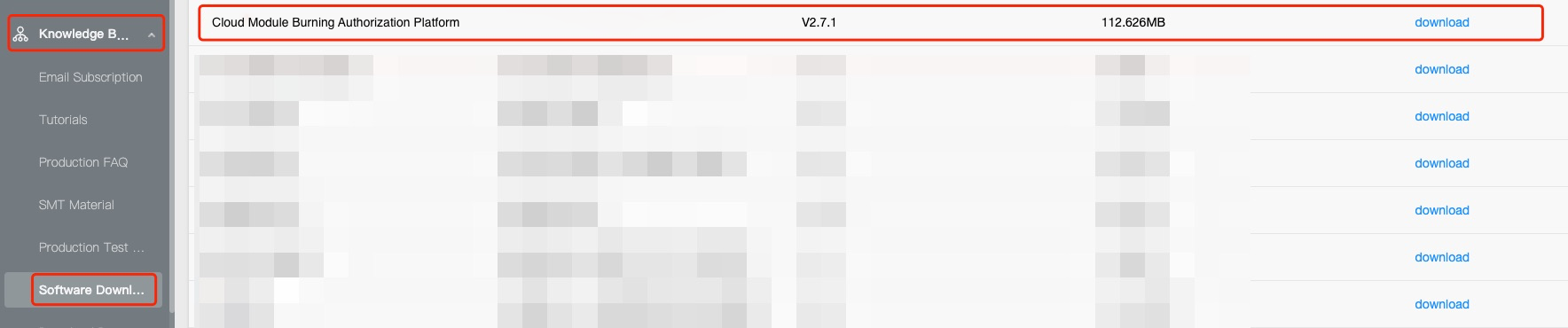
Log in to the Smart PMS. Choose Knowledge Base Management > Software Download. Find Cloud Module Burning Authorization Platform and download it.
-
Install the software.
Open the installer. When you are prompted with the following window, click More info and then click Run anyway.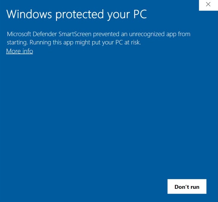
-
Follow the onscreen instructions to begin installing. You can specify an installation directory as needed.
After installation, open the software and log in with your Smart PMS account and password. Click Network Module to install the flashing and authorization software. -
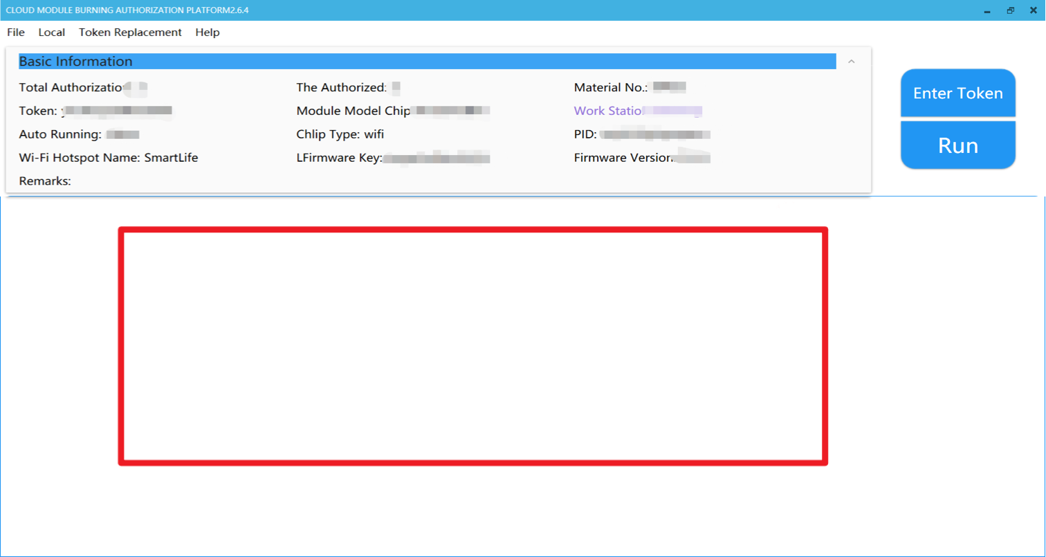
After installation, if you have a white blank screen as shown in the following figure, you need to set the software to make it run correctly. If you have a yellow screen, it means the installation is successful.
-
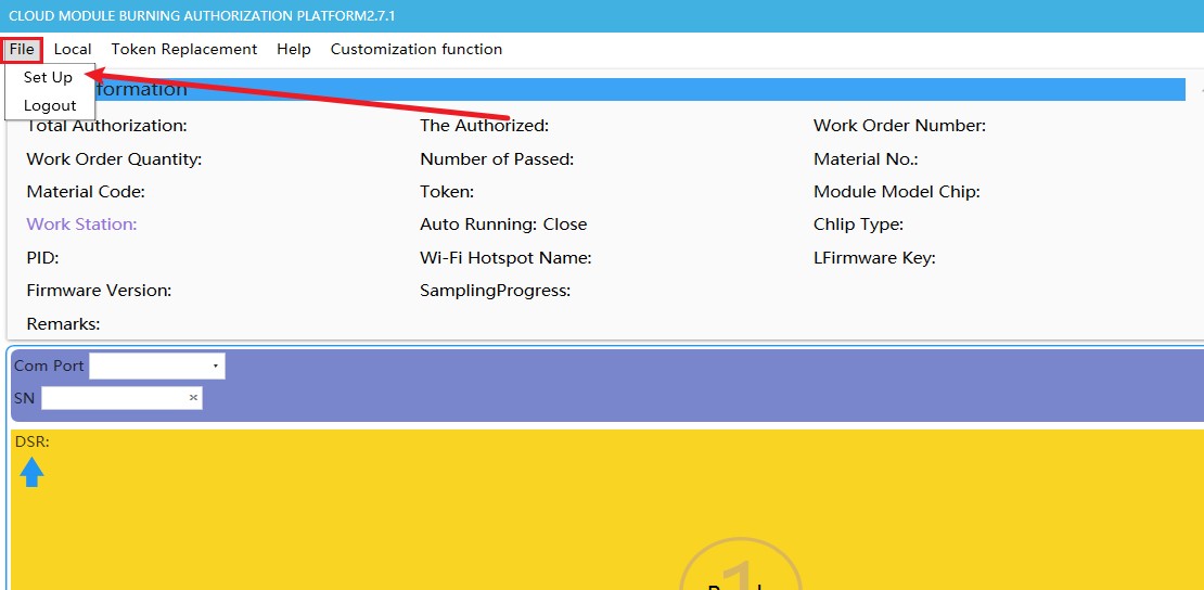
Choose File > Set Up.
-
Change 1*1 for Multi Selection to 1*2 and click OK.
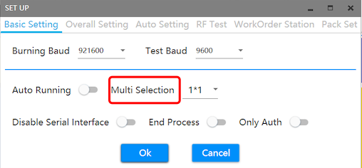
-
You will have two yellow screen sections.
-
Then, change 1*2 back to 1*1. This software will work fine.
-
-
Get application code
Open Ubuntu. Use the cd command to navigate to the apps directory of the SDK. Run the following command to download the sample code from GitHub.
git clone https://github.com/Tuya-Community/bk7231n_light1_io_xx.git
Assume that you are in the /home/share/samba/ty_iot_sdk_bk7231n_2.3.1/apps. Navigate to the apps directory and run the following command to download the code. Alternatively, visit the GitHub repository, download the code, and copy it to the apps directory.
Create a folder named bk7231n_light1_io_xx under the apps directory of the SDK. The folder name will be the project name and the firmware identifier. Make sure to give it a unique name to differentiate multiple projects.
You can use this naming rule: chipset platform + product type + product feature + manufacturer or individual name initials.
Take bk7231n_light1_io_xx as an example. bk7231n indicates the chipset platform. light1 indicates cool white light. io indicates LED on/off is controlled by high and low signals. xx is the name initials.
Edit code
You can edit the information as instructed in this step or leave the default parameter as is and directly move to the next step.
Under the /apps/bk7231n_light1_io_xx/include directory, open tuya_device.h and replace the PRODECT_ID with your own value.
#ifndef __TUYA_DEVICE_H__
#define __TUYA_DEVICE_H__

/* Includes ------------------------------------------------------------------*/
#include "tuya_cloud_types.h"
#include "tuya_cloud_com_defs.h"

/* Exported types ------------------------------------------------------------*/
/* Exported constants --------------------------------------------------------*/
/* Exported macro ------------------------------------------------------------*/
#ifdef __cplusplus
    extern "C" {
#endif /* __cplusplus */

#ifdef _TUYA_DEVICE_GLOBAL
    #define _TUYA_DEVICE_EXT
#else
    #define _TUYA_DEVICE_EXT extern
#endif /* _TUYA_DEVICE_GLOBAL */

// device information define
#define DEV_SW_VERSION USER_SW_VER
#define PRODECT_ID "fnrwpglflmbhjvvh" /* Replace the PID with your own value. */

/* Exported functions ------------------------------------------------------- */

_TUYA_DEVICE_EXT \
OPERATE_RET device_init(VOID_T);

#ifdef __cplusplus
}
#endif /* __cplusplus */

#endif /* __TUYA_DEVICE_H__ */
Under the /apps/bk7231n_light1_io_xx/src directory, open tuya_device.c and set WIFI_KEY_PIN in line 38 to the reset button pin.
Under the /apps/bk7231n_light1_io_xx/include directory, open light_system.h and set LIGHT_PIN to the LED pin.
Compile project
Compilation
In Ubuntu terminal, navigate to the build_app.sh directory and run the following command to compile code.
sh build_app.sh ./apps/bk7231n_light1_io_xx bk7231n_light1_io_xx 1.0.0
Assume that you are in the /home/share/samba/ty_iot_sdk_bk7231n_2.3.1/.
| Commands | Description |
|---|---|
| sh build_app.sh | Use the shell command to execute the build_app.sh script. |
| ./apps/tuya_demo_light_pwm | The path where the project resides. |
| tuya_demo_light_pwm | The firmware identifier. It must be identical to the project folder name. |
| 1.0.0 | The software version number. |
Production output
The generated files are sorted by version and stored in the output folder.
Assume that you are to compile the bk7231n_light1_io_xx project in the apps folder, and its version is 1.0.0. The generated files will be stored in the apps/bk7231n_light1_io_xx/output/1.0.0 directory, as shown in the following figure.
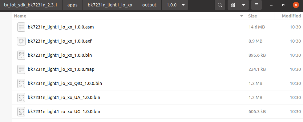
Take care of the three files: bk7231n_light1_io_xx_QIO_1.0.0.bin, bk7231n_light1_io_xx_UA_1.0.0.bin, and bk7231n_light1_io_xx_UG_1.0.0.bin.
| File name | Feature |
|---|---|
bk7231n_light1_io_xx_QIO_1.0.0.bin |
Production firmware: boot, user area firmware, and detection firmware. |
bk7231n_light1_io_xx_UA_1.0.0.bin |
User area firmware |
bk7231n_light1_io_xx_UG_1.0.0.bin |
Firmware updates |
Upload firmware
You must upload the custom firmware to the Tuya Developer Platform and then flash the UA file to the hardware. Otherwise, device pairing will fail.
-
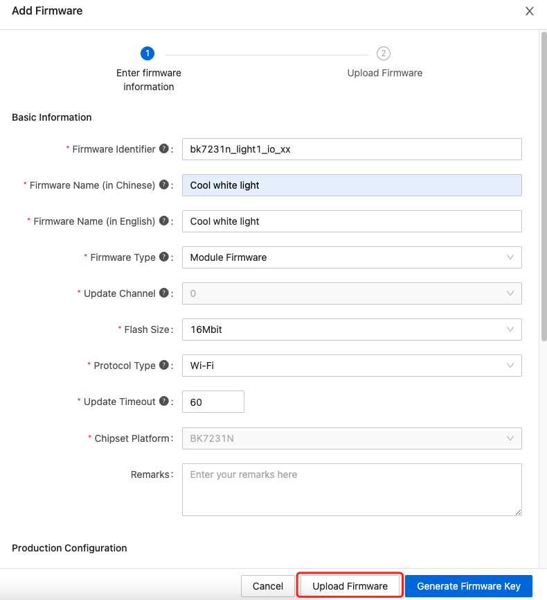
Log in to the Tuya Developer Platform. Under the Hardware Development tab, click Add custom firmware and complete the required information. Click Upload Firmware.
-
The Firmware Identifier must be identical to the name of the project folder under the
appsdirectory. Assume that the firmware identifier iswifi_one_light. You should upload the production file of the projectwifi_one_lightunder theappsdirectory. -
The Flash Size is
16 Mbit, equal to 2 MB. Check out the flash size of your module from Network Modules documentation.1 byte = 8 bits 16 Mbit ÷ 8 = 2 MB
-
-
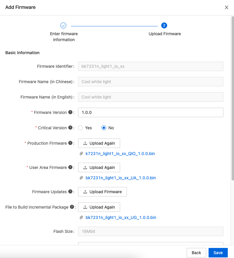
The Firmware Version must be identical to the one used for compilation. For Production Firmware, upload the binary file with the suffix
QIO. For User Area Firmware, upload the binary file with the suffixUA. For Firmware Updates, upload the binary file with the suffixUG. Click Save.Make sure you select the correct file to upload.
-
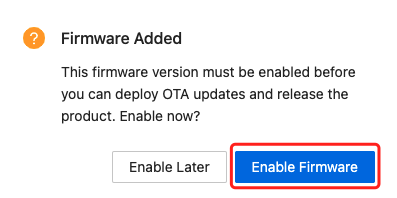
Click Enable Firmware.
-
Choose General availability for deployment scope and click Save and Enable.
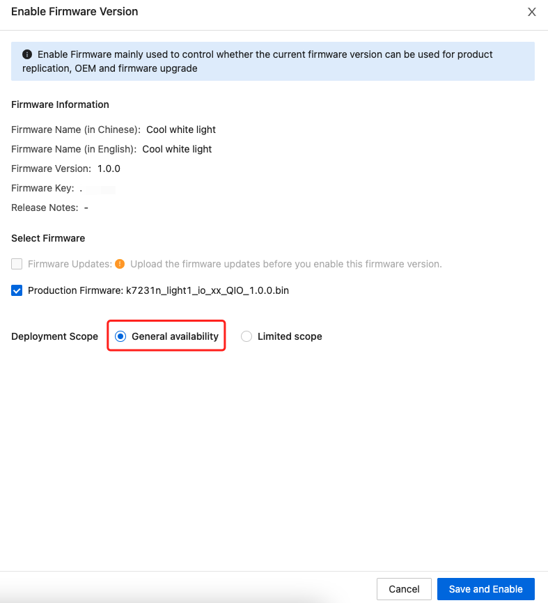
If your product is built for mass production, proceed with caution when choosing the development scope.
Get production credentials
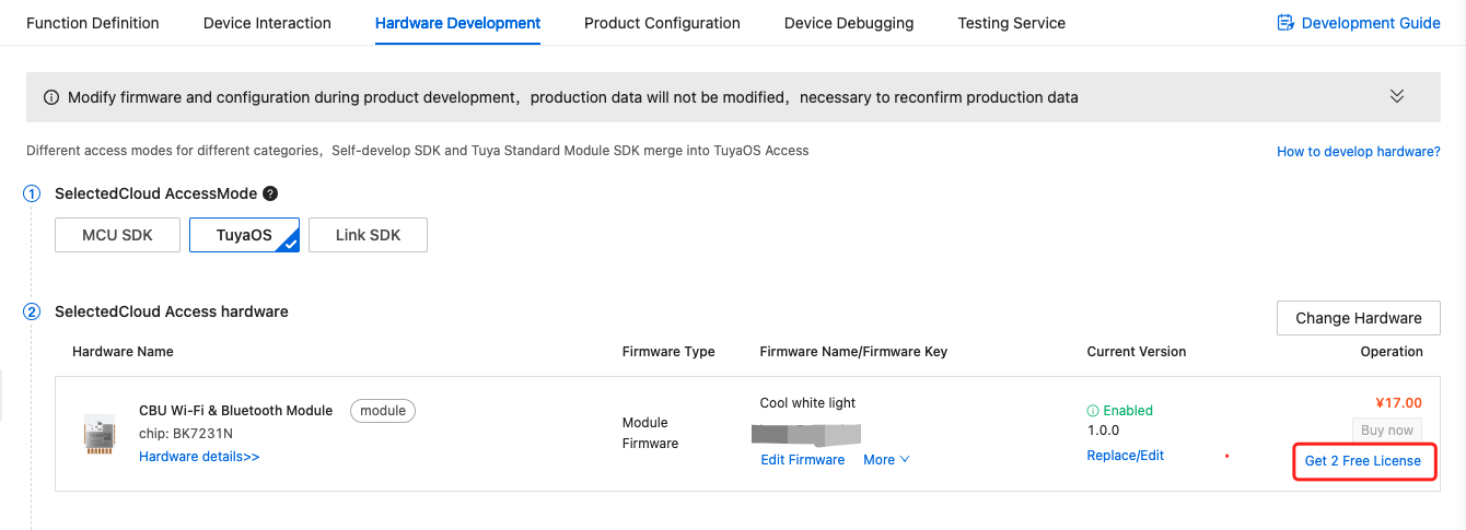
For more information about the account and tools used for firmware flashing, see Flashing and Authorization. After uploading firmware to the platform, request two free licenses for debugging your project.
-
Click Get 2 Free Licenses.
-
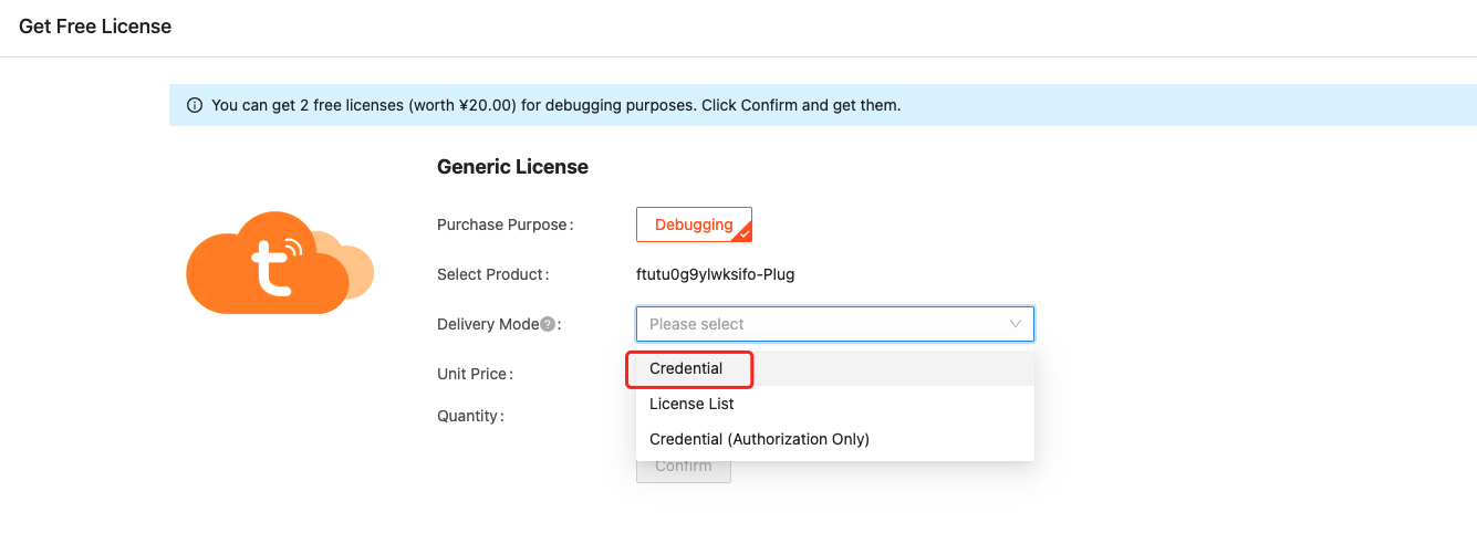
For Delivery Mode, choose Credential and click Submit.
- Credential: The flashing and authorization software writes a unique credential to a device. It can read the specified numbers of credentials and write them to devices in bulk. To use credentials, make sure you have uploaded the production firmware to the platform.
- License List: A list provides license information in plain text, which must be written to devices manually one by one.
- Credential (Authorization Only): The flashing and authorization software writes a unique credential to a device for the purpose of authorization only without the need for firmware.
-
Click View Order List.
-
Find your product by PID and click Download Credential.
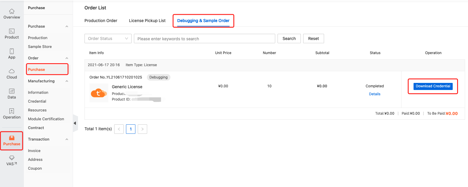
-
Extract the downloaded file and open the
Token_information.txtfile. Copy the credential. Open the software, enter your credential in the token input box, and select Burning Authorization for the work station. -
If you get an error message saying Failed to get token, no permissions for actions, try troubleshooting with the following steps.
Visit Smart PMS. Choose Production Manage > Work Order Management > Activation Code Verification. Enter your credential with issue and click OK. Go back to the software. Enter your credential again and you should be good to go.
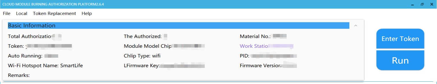
-
Your screen will look like the figure below. Basic Information displays the firmware states.
Flashing and authorization
Flip the four toggles on the CBU Nano board to the ON position to enable flashing and logging.
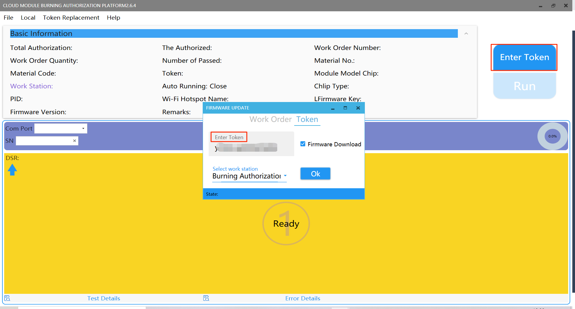
-
Open the software, click Enter Token, enter your credential, select Burning Authorization for the work station, and click OK.
-
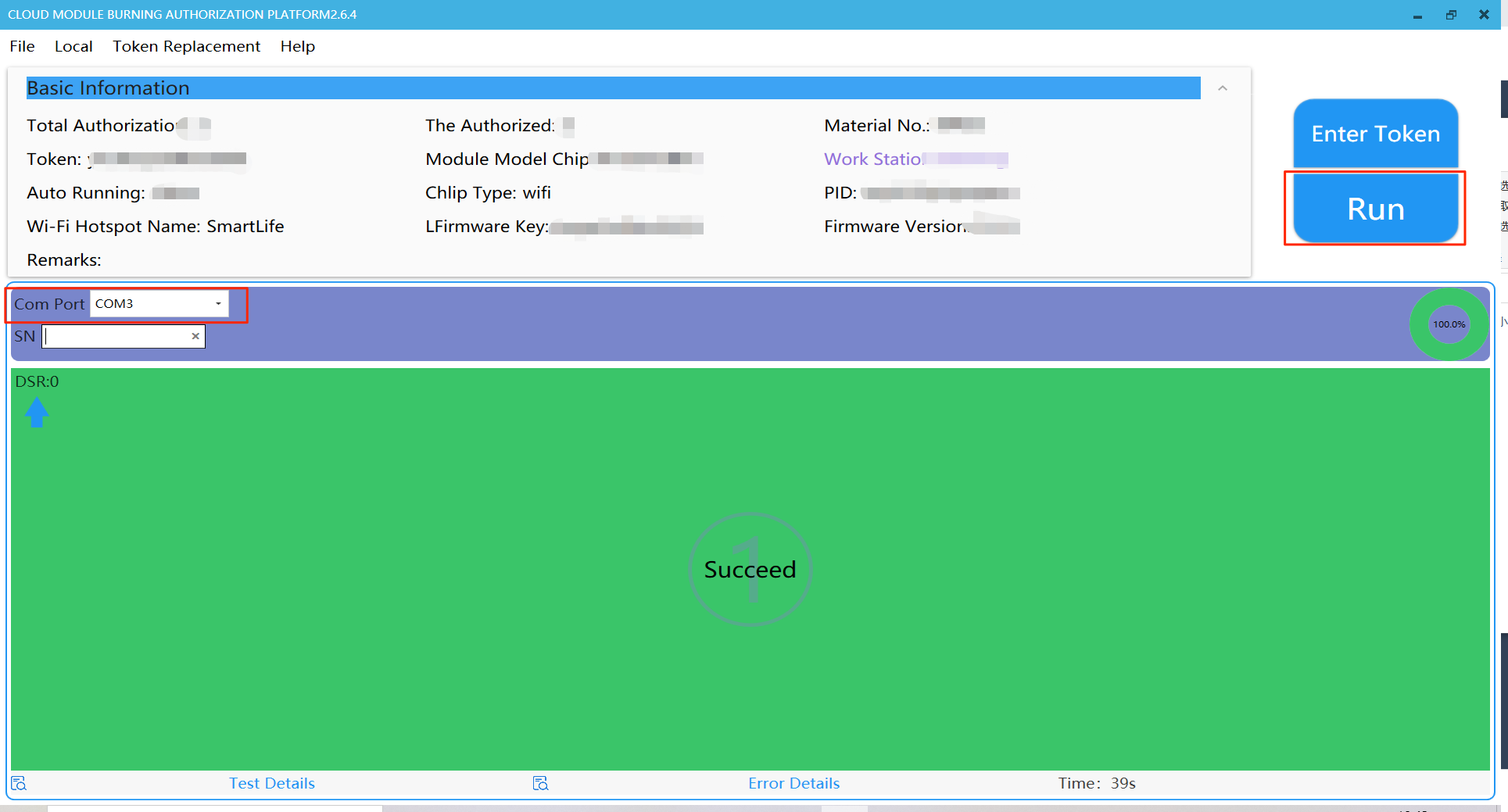
Connect your board to your computer. The pin connection table is as below:
USB to UART converter pins CBU Nano board pins VCCVCCGNDGNDTXRXRXTXSelect the correct COM Port and click Run. Immediately power off the board and power on it again. Alternatively, you can directly press the reset button to restart the board.
To restart the board, do not directly disconnect the USB to UART converter from your computer. Otherwise, flashing will fail. You should disconnect the VCC and GND jumper wires between the board and the USB to UART converter and connect them again.
The CBU Nano board comes with a USB to serial CH340 chip. After you click Run on the software, press the reset button on the board to restart it.
-
If you failed to enter the production test, it might be because the board has been connected to the network for more than 15 minutes and the testing channel has been shut down. For more information about this issue, see Troubleshoot Production Test Failures.
Device pairing
After the firmware is flashed to the module, you can use the SmartLife app to connect the module to the cloud for remote control. You can download the app for iOS or Android from app stores or scan the following QR code and download.

Things to note:
If you use Tuya’s flashing and authorization software, your board will enter pairing mode after a restart on successful flashing.
If you use the chip manufacturer’s flashing tool and your board has been paired, your board will connect to the last connected network after a restart. This is because the board is only flashed with firmware without the PID being replaced. In this case, reset the board to make it enter pairing mode.
The pairing processes vary depending on the modules for use. The CBU module is Wi-Fi and Bluetooth Low Energy (LE) combo. It uses 2.4 GHz Wi-Fi network.
Wi-Fi and Bluetooth LE combo devices
The family of Wi-Fi and Bluetooth LE combo modules includes the WB series, WBR series, JWBE series, CB series, CR series, and HPWSMS1 modules.
-
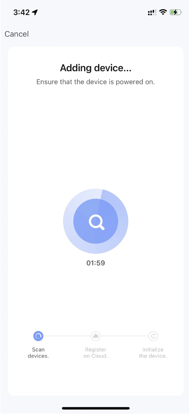
When the device is in pairing mode, open the SmartLife app. It will be displayed on the app.
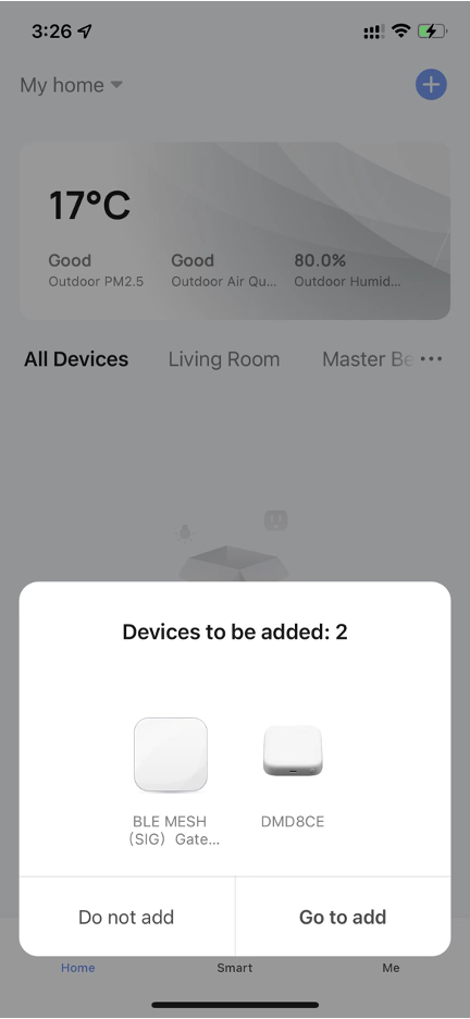
-
The Wi-Fi and Bluetooth LE combo module receives the information for pairing to the device from the mobile app over Bluetooth. The app automatically searches for devices pending pairing.
-
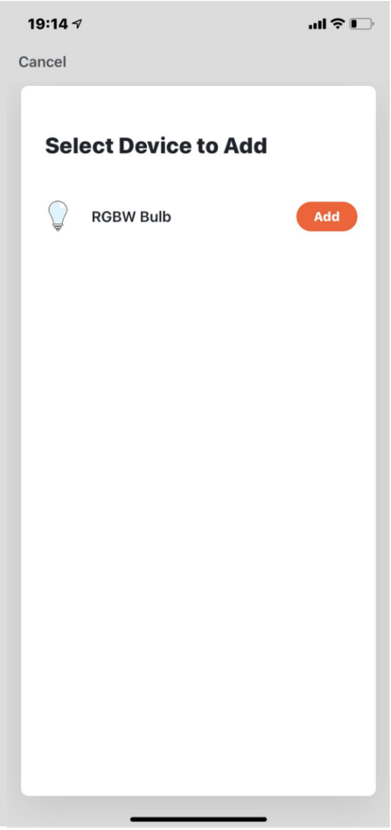
When your device is discovered, select it and tap the + icon.
-
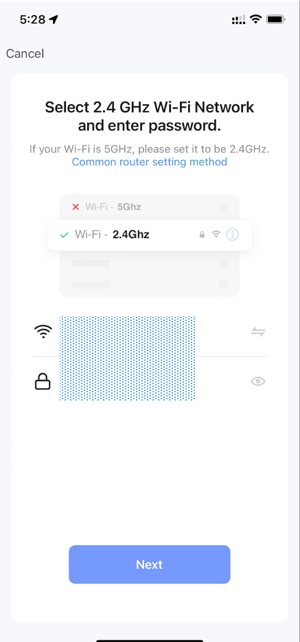
Check for the Wi-Fi SSID and password that appeared on the screen. If the password input box is empty, enter the password.
-
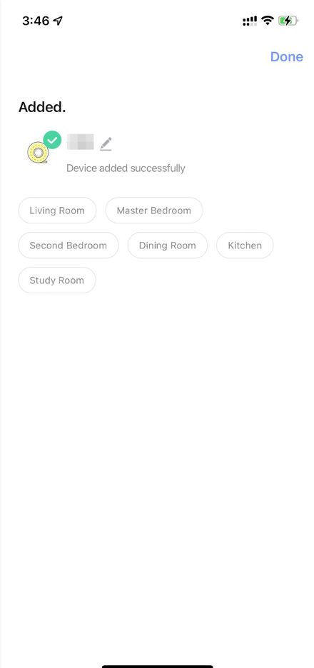
If your device is added successfully, you can use the app to control it.
Wi-Fi devices
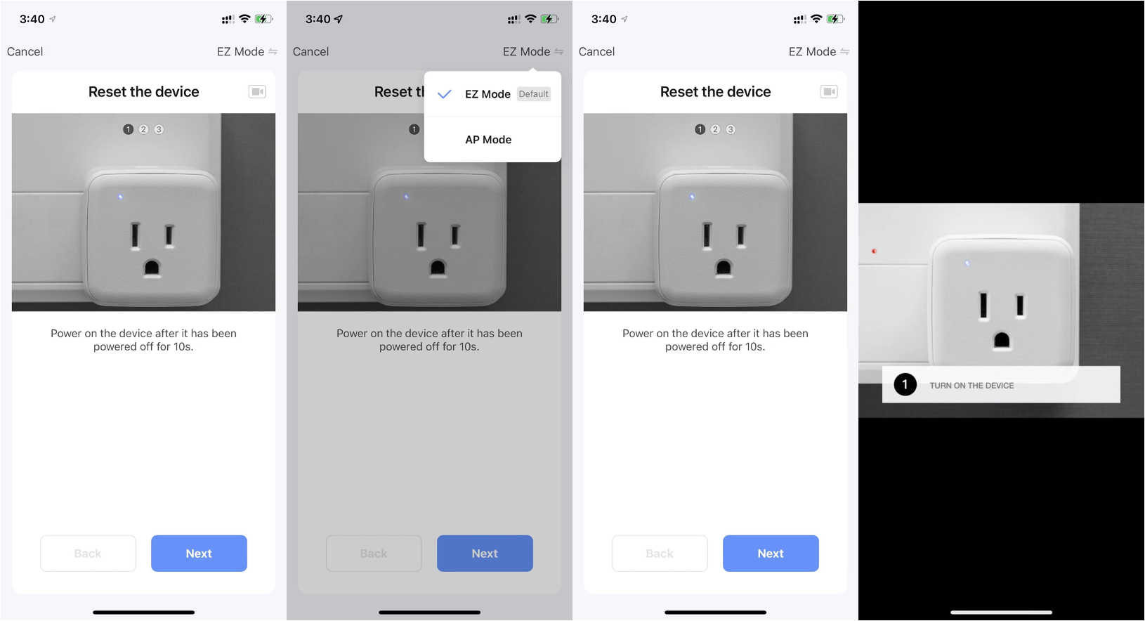
For Wi-Fi devices without a Bluetooth feature, pair them through the EZ or AP mode.
-
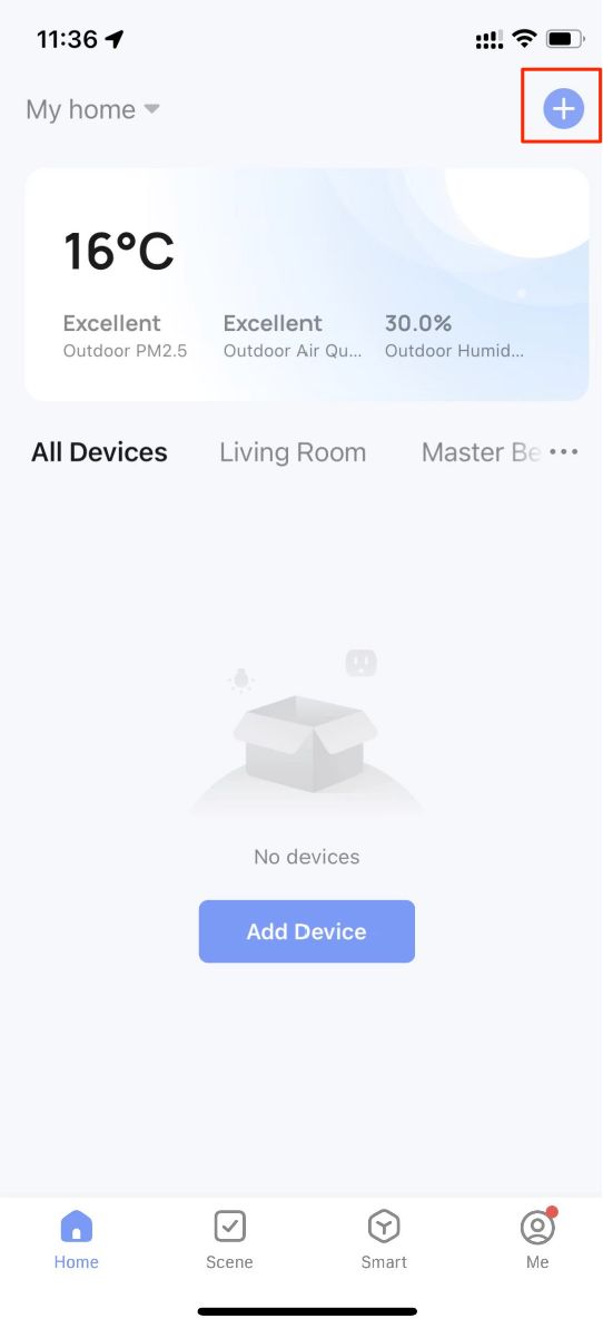
Open the SmartLife app. Tap + in the top right corner and then Add Device.
-
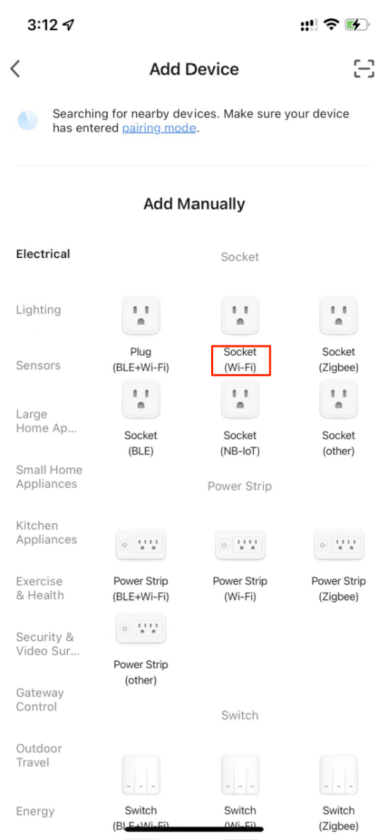
From the product categories, tap a device icon with Wi-Fi.
-
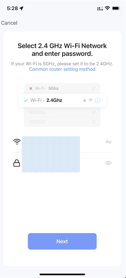
Make sure you are using the 2.4 GHz Wi-Fi and enter the correct password.
-
Reset your device as instructed to make it enter pairing mode.
-
Wait for a while to finish pairing.
-
If your device is added successfully, you can use the app to control it.
Is this page helpful?
YesFeedbackIs this page helpful?
YesFeedback


