Smart Plug
This topic describes how to develop a smart plug with Tuya standard Zigbee module. We use the smart plug demo in the SDK as an example to illustrate this process.
Get the demo
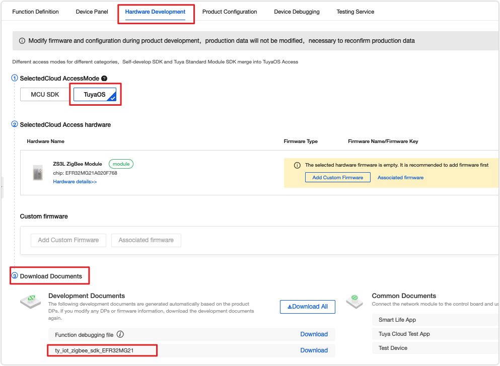
Before downloading the SDK, make sure you have created a Zigbee product on the Tuya Developer Platform. Go to Hardware Development, choose TuyaOS, and select the desired network module. Then, in the Download Documents area, download the SDK. The SDK contains several demos to help you understand how to prototype a Zigbee product.
Demo directory
Extract the downloaded file and find the apps folder that contains demos. The directory of the smart plug demo is as follows.
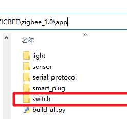
The directory of the app folder:
    app
     ├── build-all.py
     ├── light
     ├── sensor
     ├── smart_plug
     └── switch
           ├── common
           │   ├── include
           │   └── src
           └── project
                 └── sample_switch1
                          ├── documents
                          ├── EFR32MG13P732F512
                          ├── EFR32MG21A020F768
                          ├── include
                          ├── src
                          ├── pre-build.py
                          └── pre-build-iar.py
The description of files included in the sample_switch1 folder:
| Folder/File | Description |
|---|---|
| EFR32MG13P732F512 | The entry to build EFR32MG13P732F512 chip based project. The folder includes project files for IAR and GCC compiler. |
| EFR32MG21A020F768 | The entry to build EFR32MG21A020F768 chip based project. The folder includes project files for IAR and GCC compiler. |
| include | Contains the .h header file of the application project. |
| src | Contains the .c source code of the application project. |
| pre-build.py | The script for GCC compiler. Modification of this file is not required. |
| pre-build-iar.py | The script for IAR compiler. Modification of this file is not required. |
| switch/common | Contains the common build files if needed. |
Code implementation
This section describes how the sample code works and how to write code to implement smart plug features.
Communication logic
The following describes how a device interacts with the cloud.
-
Data exchange
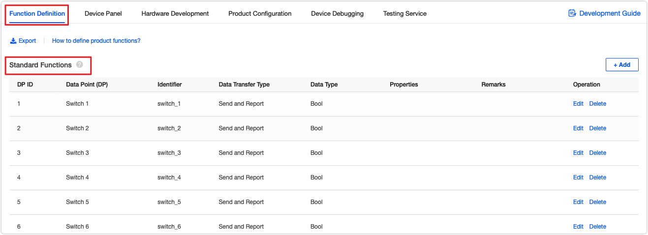
The Zigbee device sends data to the gateway. The gateway parses the received data in the format required by the Tuya-defined protocol and then sends the parsed data in JSON to the cloud. The data identifier and definition are configured in the Function Definition step when you create a product on the Tuya Developer Platform.
-
Device identifier
-
A product ID (PID) is a unique identifier assigned to each product that is created on the Tuya Developer Platform. A PID is associated with product configurations, such as app panel, cloud configuration, and voice capability. You need to write the PID of your product to the
package.jsonfile in the demo. -
The firmware fingerprint comprises the firmware identifier and the firmware version. In the production process, the host reads the firmware fingerprint to verify the firmware information.
-
The firmware identifier and firmware version can be specified in the
package.jsonfile. Thenamefield represents the firmware identifier (generally the project name) and theversionfield represents the firmware version (in the formatx.x.x).The firmware identifier and version number specified in the
package.jsonfile must be consistent with the one configured on the Tuya Developer Platform. Otherwise, the license authorization will fail.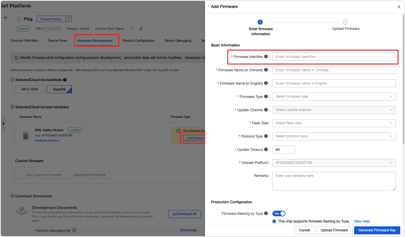
-
module_namerepresents the name of the module you use. -
model_idrepresents the model ID of a Zigbee device, which is used to identify the Zigbee device type by the gateway. For more information, see the Zigbee Connectivity Specifications.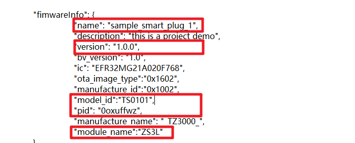
-
-
License authorization
To connect your Zigbee device permanently to the cloud, you must perform license authorization. Otherwise, the cloud connection is only valid for seven days. For more information, see Flashing and Authorization Guide.
Demo features
The following table lists the features the demo can implement.
| Feature | Implementation methods |
|---|---|
| Local control | Detect the state of the pushbutton and control the signal that a relay outputs to switch on or off the device accordingly. The device will report its current status to the gateway. Then, the gateway sends the data to the cloud. |
| Network forming | After the pushbutton is pressed and held for a specified period such as 10 seconds, the network forming function is called to make the device enter the network forming mode. |
| Status indication | Determine the current status of the device and indicate the status by LED activities including steady on, steady off, and blinking. |
| Network forming controlled by mobile app | The SDK contains the implementation of this feature. After the device enters the pairing mode, you can operate network forming by using the mobile app. |
| Remote control by mobile app | Parse the commands from the cloud and control the hardware accordingly. After that, the device reports its current status to the cloud. |
| Removing devices by mobile app | Call the device reset function to make the device enter the pairing mode. |
| Voice control | The implementation code for voice control shares the same control logic for device control. |
| OTA updates | Receive updates from the cloud and install them on the device. |
| Production testing | Perform a test through UART communication or scanning for beacon signals. |
Feature implementation
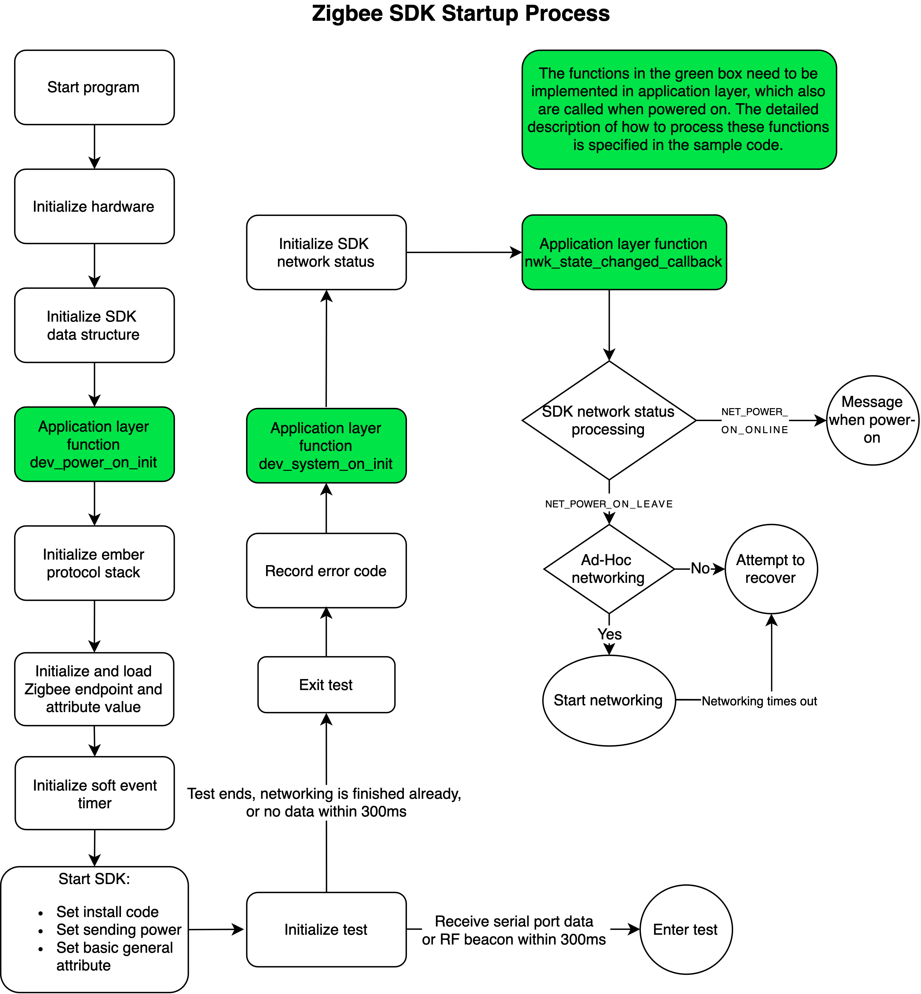
Before directly moving to how the demo code implements device management and control, we describe how SDK initialization works.
This section describes the feature code. In some cases, several features can be implemented by one function so only the unique code is displayed and shared code is represented with *****.
Basic functions
Take care of the following important crucial functions.
dev_power_on_init();     // Initialization after power on.
dev_system_on_init();   // Initialization after the stack and system components are started.
dev_mf_test_callback();        // The user callback of production testing.
nwk_state_changed_callback(); // The callback of network status changes.
-
Configure firmware information
Before configuring firmware information, make sure you have created a product on the Tuya Developer Platform. Find the
package.jsonfile and replace the information in the following code snippet with your own.package.json { "fimwareInfo": { "name": "oem_si32_zg_plug_10A_USB_dlx", // The firmware name. "description": "ZigBee switch common", // The firmware description. "version": "1.0.9", // The firmware version. "bv_version": "1.0", // A fixed value. Modification is not required. "ic": "efr32mg13p732gm48", // The Zigbee chip model. "ota_image_type":"0x1602", // A fixed value for OTA updates. Modification is not required. "manufacture_id":"0x1002", // A fixed value for OTA updates. Modification is not required. "model_id":"TS0105", // The mode ID is used to quickly identify the type of Zigbee device by the gateway. "pid": "ZHahfZRP", // The PID of your product. "manufacture_name": "_TZ3000_",// The prefix of the PID, used to determine the applicable protocol by the gateway. "module_name":"ZS3L" // The model of your Zigbee module. } } -
Create Zigbee devices and set up network forming parameters
Zigbee device creation depends on the network connection so
dev_power_on_init()must be implemented. The following code uses the smart plug as an example to describe the process of creating Zigbee devices.const attr_t g_group_attr_list[] = { GROUP_ATTR_LIST }; const attr_t g_scene_attr_list[] = { SCENE_ATTR_LIST }; #define ON_OFF_PRIVATE_ATTR_LIST \ { 0x0000, ATTR_BOOLEAN_ATTRIBUTE_TYPE, 1, (ATTR_MASK_TOKEN_FAST), (uint8_t*)0x00 }, \ const attr_t g_light_attr_list[] = { ON_OFF_PRIVATE_ATTR_LIST }; const cluster_t g_server_cluster_id[] = { DEF_CLUSTER_GROUPS_CLUSTER_ID(g_group_attr_list) DEF_CLUSTER_SCENES_CLUSTER_ID(g_scene_attr_list) DEF_CLUSTER_ON_OFF_CLUSTER_ID(g_light_attr_list) }; #define SERVER_CLUSTER_LEN get_array_len(g_server_cluster_id) /** * @note Represents one `ON_OFF_LIGHT` device, one endpoint. * Support group, scene, and on/off cluster on the server. * Correspond to attributes `GROUP_ATTR_LIST`, `SCENE_ATTR_LIST`, and `ON_OFF_PRIVATE_ATTR_LIST` respectively. */ const dev_description_t g_dev_des[] = { { 0x01, ZHA_PROFILE_ID, ZG_DEVICE_ID_ON_OFF_LIGHT, SERVER_CLUSTER_LEN, (cluster_t *)&g_server_cluster_id[0], 0, NULL}, }; void dev_power_on_init(void) { zg_dev_config_t g_zg_dev_config; join_config_t cfg; /** * @note Describe a device in terms of the number of endpoints and the associated clusters and attributes of each endpoint. */ dev_register_zg_ep_infor((dev_description_t *)g_dev_des, EP_SUMS); /** * @note Configure the Zigbee device as a router device. */ memset(&g_zg_dev_config, 0, sizeof(zg_dev_config_t)); g_zg_dev_config.dev_type = ZG_ROUTER; dev_register_zg_dev_config(&g_zg_dev_config); /** * @note Configure auto network forming after power on or remote deletion. The timeout period is one minute. */ memset(&cfg, 0, sizeof(cfg)); cfg.auto_join_power_on_flag = TRUE; cfg.auto_join_remote_leave_flag = TRUE; cfg.join_timeout = 60000; dev_zg_join_config(&cfg); return; -
Join and leave a Zigbee network
-
dev_zigbee_join_start()can be called to leave the current network and then join a new one. -
dev_zigbee_leave_for_user()can be called to leave the current network without joining a new network. -
You can implement a button press handler to trigger network joining and leaving through button events.
/* * @note __dev_key_handle Assume that this is a registered button press handler. */ static void __dev_key_handle(uint32_t key_id, key_st_t key_st, uint32_t push_time) { switch(key_id) { case KEY_1_INDEX: { if(key_st == KEY_ST_PUSH) { /// The button is being pressed. if(push_time == 3000) { /// After the button is pressed and held for 3,000 ms, the LED2 starts blinking. dev_led_start_blink(LED_2_INDEX, 500, 500, DEV_LED_BLINK_FOREVER, DEV_IO_OFF); /// The LED1 alternately outputs high for 500 ms and low for 300 ms to emit blinking signals. } } else { if(push_time < 3000) { /// If the button is pressed and held for less than 3,000 ms, it is recognized as a short press. //TODO: } else { dev_zigbee_join_start(60000); // / After the button is pressed and held for more than three seconds, network forming is triggered. The network forming times out after one minute. } } break; } case KEY_2_INDEX: { if(key_st == KEY_ST_PUSH) { /// The button is being pressed. if(push_time == 3000) { /// After the button is pressed and held for 3,000 ms, the LED2 starts blinking. dev_led_start_blink(LED_2_INDEX, 500, 500, DEV_LED_BLINK_FOREVER, DEV_IO_OFF); // / The LED1 alternately outputs high for 500 ms and low for 300 ms to emit blinking signals. } } else { if(push_time < 3000) { /// If the button is pressed and held for less than 3,000 ms, it is recognized as a short press. //TODO: } else { dev_zigbee_leave_for_user(); // / After the button is pressed and held for more than three seconds, network leaving is triggered. dev_led_stop_blink(LED_2_INDEX, DEV_IO_ON); // / If the LED is steady on, it means the network leaving state. } } break; } default: { break; } } } -
-
Manage Zigbee gateway heartbeat
Set a heartbeat mechanism to detect the connection between the Zigbee device and the gateway as well as to refresh the router. Since the heartbeat transmission relies on the system software timer, you must call
dev_heartbeat_setindev_system_on_init()or in the subsequent procedure. If the heartbeat checking is not performed either on the Zigbee device or the gateway regularly, the device status displayed on the mobile app will be offline.The SDK will schedule the heartbeats based on the device type. You can also make an explicit call to change the default setting. The following code shows an example implemented in
dev_system_on_init().void dev_system_on_init(void) { dev_heartbeat_set(APP_VERSION, 180000); // / < 180s + 30s. Send a heartbeat at a random value. } -
Zigbee network status
The SDK provides a callback to report the current network status of the Zigbee gateway. You can implement an LED indication of network status. Here is a sample code of the callback:
void nwk_state_changed_callback(NET_EVT_T state)
{
	switch(state) {
		case NET_POWER_ON_LEAVE: {
			//TODO: Network not connected after power on.
			break;
		}
		case NET_JOIN_START: {
			//TODO: Initiate network forming.
			break;
		}
		case NET_JOIN_TIMEOUT: {
			//TODO: Network forming failed.
			break;
		}
		case NET_POWER_ON_ONLINE: {
			//TODO: Network connected after power on.
			break;
		}
		case NET_JOIN_OK: {
			//TODO: Network forming succeeded.
			break;
		}
		case NET_REJOIN_OK: {
			//TODO: Connection retry succeeded.
			break;
		}
		case NET_LOST: {
			//TODO: Lost connection to parent.
			break;
		}
		case NET_REMOTE_LEAVE: {
			//TODO: Notify of leaving network initiated by remote control.
			break;
		}
		case NET_LOCAL_LEAVE: {
			//TODO: Notify of leaving network initiated by local control.
			break;
		}
		case NET_MF_TEST_LEAVE: {
			//TODO: Notify of leaving network initiated by production testing.
			break;
		}
		default: {
			break;
Remote control by mobile app
After the device is paired, you can control it by using the mobile app. dev_msg_recv_callback() is used to receive data from the Zigbee gateway. The following code snippet uses the switch as an example to show you the data reception handler.
ZCL_CMD_RET_T dev_msg_recv_callback(dev_msg_t *dev_msg)
{
    ZCL_CMD_RET_T result = ZCL_CMD_RET_SUCCESS;

    switch (dev_msg->cluster) {
        case CLUSTER_PRIVATE_TUYA_CLUSTER_ID: { // Process the private data.
            uint8_t len = dev_msg->data.bare_data.len;
            uint8_t *data = dev_msg->data.bare_data.data;
            //TODO: Implement your private protocol.
            break;
        }

                // Process the standard data.
        case CLUSTER_ON_OFF_CLUSTER_ID: {
            attr_value_t *attr_list = dev_msg->data.attr_data.attr_value;
            uint8_t attr_sums = dev_msg->data.attr_data.attr_value_sums;
            uint8_t i;

            for(i=0; i<attr_sums; i++) {
                switch(attr_list[i].cmd) {
                    case CMD_OFF_COMMAND_ID: {
                        //TODO: Turn off the switch.
                        break;
                    }
                    case CMD_ON_COMMAND_ID: {
                        //TODO: Turn on the switch
                        break;
                    }
                    case CMD_TOGGLE_COMMAND_ID: {
                        //TODO: Negation command
                        break;
                    }
                    default: {
                        break;
                    }
                }
                break;
            }

        }
        default:
            // Unrecognized cluster ID, error status will apply.
            break;
    }

    return result;
}
Report data to the cloud
The Zigbee device reports data to the gateway and then the gateway syncs the data with the cloud and the mobile app.
static void __send_result_cb(SEND_ST_T st, dev_send_data_t *msg)
{
    switch(st) {
        case SEND_ST_OK: {
            //TODO: Data is sent successfully.
            break;
        }
        default: {
            //TODO: Failed to send the data.
            break;
        }
    }
}

static void send_data_demo(void)
{
    dev_send_data_t send_data;

    memset(&send_data, 0, sizeof(dev_send_data_t));

    send_data.zcl_id = 0;  /// The user-defined ID, which is returned in the sending callback.
    send_data.qos = QOS_1; /// Data packet will be sent again if no acknowledgement is received.
    send_data.direction = ZCL_DATA_DIRECTION_SERVER_TO_CLIENT;
    send_data.command_id = CMD_REPORT_ATTRIBUTES_COMMAND_ID;       /// The command used to report property values.
    send_data.addr.mode = SEND_MODE_GW;                            /// Send data to the gateway.
    send_data.addr.type.gw.cluster_id = CLUSTER_ON_OFF_CLUSTER_ID; /// The on/off property.
    send_data.addr.type.gw.src_ep = 1; /// The endpoint.
    send_data.delay_time = 0;   /// The timer for delaying packet sending.
    send_data.random_time = 0;  /// The time range for random sending.
    send_data.data.zg.attr_sum = 1;  /// The number of properties to be reported.
    send_data.data.zg.attr[0].attr_id = ATTR_ON_OFF_ATTRIBUTE_ID; /// The status of the on/off property.
    send_data.data.zg.attr[0].type = ATTR_BOOLEAN_ATTRIBUTE_TYPE; /// The data type of the property.
    send_data.data.zg.attr[0].value_size = 1;                     /// The data length of the property.
    send_data.data.zg.attr[0].value[0] = 1; /// 1 means ON. 0 means OFF.
    dev_zigbee_send_data(&send_data, __send_result_cb, 1000); /// Send the data packet. `1000` indicates that the maximum duration of packet retransmission is one second.
}
Voice control
The implementation code for voice control shares the same logic for device control using a mobile app.
To enable voice control, you must subscribe to the required voice assistant services on Tuya Value-Added Service. For more information, see Third-Party Access.
Production testing
The code-based automated test is introduced to mass production for promoting efficiency, which is called production testing.
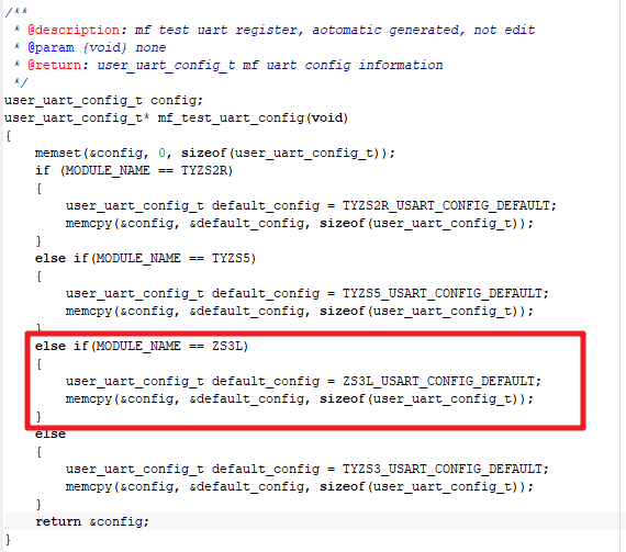
The following code snippet shows the interfaces used for production testing. You need to determine whether to initialize related interfaces.
/**
 * @description: mf test uart register, aotomatic generated, not edit
 * @param {void} none
 * @return: user_uart_config_t mf uart config information
 */
user_uart_config_t config;
user_uart_config_t* mf_test_uart_config(void)
{
    memset(&config, 0, sizeof(user_uart_config_t));
    if (MODULE_NAME == TYZS2R)
    {
        user_uart_config_t default_config = TYZS2R_USART_CONFIG_DEFAULT;
        memcpy(&config, &default_config, sizeof(user_uart_config_t));
    }
    else if(MODULE_NAME == TYZS5)
    {
        user_uart_config_t default_config = TYZS5_USART_CONFIG_DEFAULT;
        memcpy(&config, &default_config, sizeof(user_uart_config_t));
    }
    else
    {
        user_uart_config_t default_config = TYZS3_USART_CONFIG_DEFAULT;
        memcpy(&config, &default_config, sizeof(user_uart_config_t));
    }
    return &config;
}
MODULE_NAME follows the module_name field in the package.json file. If the sample code does not contain the required model name, you can configure a program for your module model. For example, if your module is ZS3L, you can write code like this:
The SDK has implemented the functions for some testing items. For example, enter testing mode, read MAC address, detect firmware version, write PID, test RF performance, get RSSI value, and verify authorization.
/**
 * @description: device manufactury test callback, when device is in manufactury test model,
 * sdk will use this callback to notify application the test item and test command;
 * @param {cmd} manufactury test type
 * @param {*args} manufactury test data
 * @param {arg_len} manufactury test data length
 * @return: none
 */
MF_TEST_RET_T dev_mf_test_callback(MF_TEST_CMD_T cmd, uint8_t *args, uint16_t arg_len)
{
    switch(cmd)
    {
        case MF_TEST_LED_ON_ALL:
        {
            dev_led_stop_blink(NET_LED_1_IO_INDEX, DEV_IO_ON);
            dev_led_stop_blink(LED_1_IO_INDEX, DEV_IO_ON);
            break;
        }
        case MF_TEST_LED_OFF_ALL:
        {
            dev_led_stop_blink(NET_LED_1_IO_INDEX, DEV_IO_OFF);
            dev_led_stop_blink(LED_1_IO_INDEX, DEV_IO_OFF);
            break;
        }
        case MF_TEST_LED_BLINK_ALL:
        {
            dev_led_start_blink(NET_LED_1_IO_INDEX, 500, 500, 4, DEV_IO_OFF);
            dev_led_start_blink(LED_1_IO_INDEX, 500, 500, 4, DEV_IO_OFF);
            break;
        }
        case MF_TEST_RELAY_ON_ALL:
        {
            dev_led_stop_blink(RELAY_1_IO_INDEX, DEV_IO_ON);
            break;
        }
        case MF_TEST_RELAY_OFF_ALL:
        {
            dev_led_stop_blink(RELAY_1_IO_INDEX, DEV_IO_OFF);
            break;
        }
        case MF_TEST_RELAY_BLINK_ALL:
        {
            dev_led_start_blink(RELAY_1_IO_INDEX, 500, 500, 4, DEV_IO_OFF);
            break;
        }
        case MF_TEST_BUTTON:
        {
            g_work_st = DEV_WORK_ST_TEST;
            return MF_TEST_DOING;
        }
        case MF_TRANSFER:
        {
        }
        default :
        {
            break;
        }
    }
    return MF_TEST_SUCCESS;
}
OTA updates
The Zigbee module comes with the OTA update feature. After the firmware build is completed, you will get two types of output files. The .s37 file is used for flashing to the chip and the .bin file is used for OTA update deployment.
/**
 * @note (OPTION) This function is called when an OTA event occurs.Includes the beginning and end of the OTA
 * @param[in] {evt} The type of OTA event. Refer to enum ZG_OTA_EVT_T definition for details.
 * @return none
 */
Build the firmware
Use sample_switch1 as an example to show you how to build projects with IAR.
-
Navigate to
silicon_labs_zigbee\app\switch\project\sample_switch1\EFR32MG13P732F512. -
Double click
tuya_sdk.ewwto open the project. -
Build the project.
Do not open your project by
Open Workspace. Otherwise, the build process might fail. BeforeRebuild All,Cleanis recommended.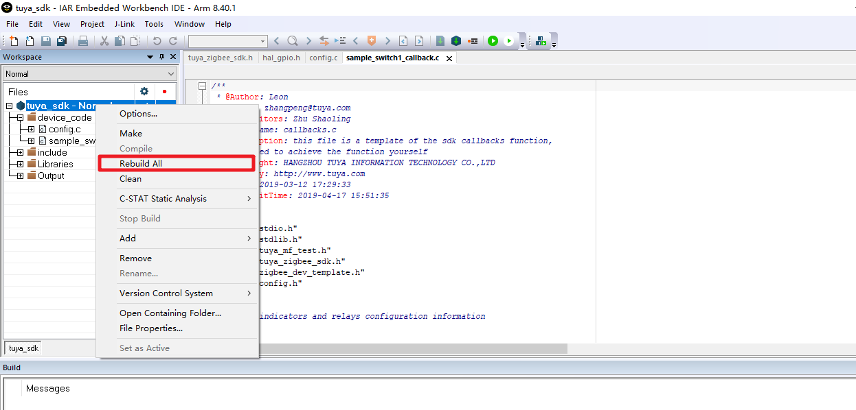
-
The build outputs are
.s37and.bin, stored in\app\smart_plug\project\sample_plug1\EFR32MG21A020F768\build\exe.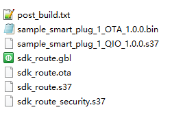
-
The file with the suffix
.s37is the firmware file that is uploaded to the Tuya Developer Platform for flashing.
Flashing and authorization
Upload the firmware file to the Tuya Developer Platform and request the free licenses. Download Tuya’s flashing tool and authorize your module. For more information, see Firmware Flashing and Authorization.
Is this page helpful?
YesFeedbackIs this page helpful?
YesFeedback


