Bluetooth Basics Demo
This topic demonstrates how to develop a Tuya-enabled Bluetooth device with TuyaOS, using the popular Bluetooth chip nRF52832 as an example.
The instructions in this topic also apply to other platforms, except for the firmware flashing procedure. Currently, the Bluetooth low energy (LE) chips compatible with TuyaOS include Nordic’s nRF52832, FREQCHIP’s FR801x, Phyplus’s PHY6222, Telink’s TLSR825x, and BEKEN’s BK3431Q and BK32881. The procedure in this topic also applies to the Bluetooth beacon and Bluetooth mesh products.
Hardware
Tuya’s proprietary development board is recommended. You can purchase the development board (part number: 2.03.99.00045) from the Tuya Developer Platform. This board uses Tuya’s Bluetooth LE dongle hardware.
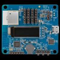
You can also use Nordic’s development boards or other nRF52832 development boards. Prepare an I2C OLED display with a resolution of 128 × 32 pixels. If you do not have a display, you can still debug other features, excluding I2C.
Software
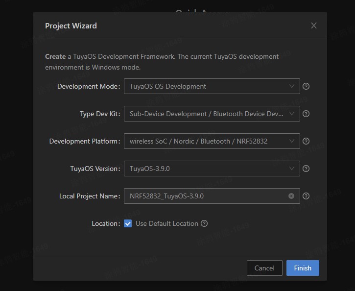
Install the TuyaOS development environment and download the latest version of TuyaOS BLE SDK (nRF52832). For detailed steps, refer to Environment Setup.
Procedure
Build and flash
-
(Optional) If your project is not intended for production, you can perform temporary authorization by altering the code. This is for debugging purposes only. Before production, make sure to change the code back.
-
Right-click
nRF52832-3.5.3/software/TuyaOS/apps/tuyaos_demo_ble_peripheral. -
Choose Build Project and wait for the building to complete.
-
To flash the full firmware, open the
nRF52832-3.5.3\software\TuyaOS\.log\hexand double-clickload_softdevice_bootloader_app.bat. (You can right-click the directory and select Flash Prod to flash the full firmware later.) See the Development Platform for other approaches to firmware flashing.
Handshake
-
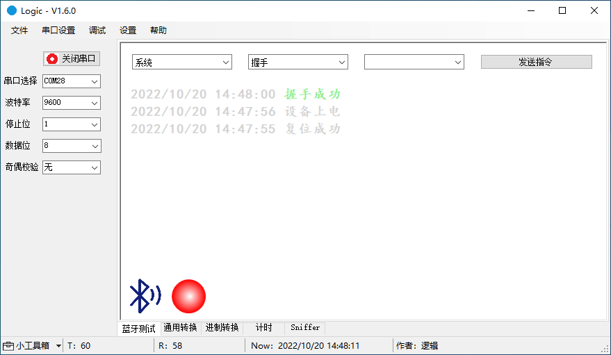
Connect Tuya’s development board to the computer using a micro-USB cable. The serial port TX is P0.06 and RX is P0.08.
-
Click to download the host software. For more information, see the Host Software User Guide. Open the host software. If you receive a pop-up window, choose More info > Run anyway. Select the correct serial port and set the baud rate 9600.
-
Choose System > Handshake and click Send Command to initiate a handshake with the device.
Pairing
Search for the Tuya app on app stores and install it on your mobile phone. Log in to the app and tap Add Device or the + in the top right corner and choose Add Device. The host software displays the updated pairing status, MTU, timestamp, and connection parameters. The figure below demonstrates the process.
Data exchange
Communicate with the mobile app using the host software that simulates a real device. You can report data, send commands, modify reported data, and present status.
The figure below demonstrates the following actions:
-
Report LED on: The LED on the panel comes on.
-
Report LED off: The LED on the panel comes off.
-
Report welcome message: A welcome message is displayed on the app panel.
-
Report custom data:
123456is displayed on the app panel. -
Report a fault: Fault 2 alert is displayed on the app panel.
-
Report a fault: The alert disappears when no fault is reported.
Debug GPIO
You can implement the following features:
- Control any GPIO to output high level or low level.
- Read the GPIO level.
- Reset the GPIO to its initial state.
- Modify the GPIO serial number directly using the host software.
The figure below demonstrates the following actions:
-
GPIO outputs high.
-
GPIO outputs low.
-
GPIO outputs high again.
-
GPIO is reset to its initial state, which has the same effect as output low.
Debug weather service
Location:
-
1: The location where the device is paired. -
2: The location where the mobile phone is.
Weather parameters:
(1 << 0), /**< temperature. */
(1 << 1), /**< high temperature. */
(1 << 2), /**< low temperature. */
(1 << 3), /**< humidity. */
(1 << 4), /**< weather condition. */
(1 << 5), /**< pressure. */
(1 << 6), /**< sensible temperature. */
(1 << 7), /**< uvi. */
(1 << 8), /**< sunrise. */
(1 << 9), /**< sunset. */
(1 << 10), /**< unix time, used with sunrise and sunset. */
(1 << 11), /**< local time, used with sunrise and sunset. */
(1 << 12), /**< wind speed. */
(1 << 13), /**< wind direction. */
(1 << 14), /**< wind speed scale/level. */
(1 << 15), /**< aqi. */
(1 << 16), /**< tips. */
(1 << 17), /**< detailed AQI status and national ranking. */
(1 << 18), /**< pm10. */
(1 << 19), /**< pm2.5. */
(1 << 20), /**< o3. */
(1 << 21), /**< no2. */
(1 << 22), /**< co. */
(1 << 23), /**< so2. */
(1 << 24), /**< weather condition mapping ID. */
A day:
1 to 7: day 1 to day 7.
The figure below demonstrates the following actions:
-
Get the current temperature for day 1.
-
Get the current temperature, highest temperature, and lowest temperature for day 1.
-
Get the current temperature, highest temperature, lowest temperature, weather conditions, air pressure, and apparent temperature for day 1.
Debug PWM
Modify the PWM frequency and duty cycle and select a channel. Mappings between channels and pins:
-
Channel 0: the pin P0.28
-
Channel 1: the pin P0.29
-
Channel 2: the pin P0.30
-
Channel 3: the pin P0.31
The figure below demonstrates the following actions:
-
Set the PWM frequency to 1000 and the duty cycle to 20%.
-
Set the PWM frequency to 1000 and the duty cycle to 50%.
-
Set the PWM frequency to 2000 and the duty cycle to 50%.
Debug scanning
Support the following features:
- Start and stop scanning.
- Modify scanning interval and window.
- Switch between proactive and passive scanning.
After scanning is started, the device will report the number of discovered devices every second.
The more devices discovered per second, the greater the scanning performance. This metric can be used to determine if the scanning is acceptable.
The figure below demonstrates the following actions:
-
Start passive scanning.
-
Start proactive scanning.
-
Stop scanning.
Debug RTC
Get and set RTC and start RTC timer (restart RTC). When the device is powered on, the RTC will start counting from zero.
The figure below demonstrates the following actions:
-
Turn on or off the serial port. Each time the serial port is restarted, a command will be sent to restart the device.
-
Get the RTC, which approaches zero, because the RTC starts counting from zero every time the device is powered on.
-
Set the RTC to 100.
-
Get the RTC again, which approaches 100.
Debug watchdog
Start the watchdog, enable and disable scheduled feeding, and stop the watchdog (if supported by the chip).
The figure below demonstrates the following actions:
-
Start the watchdog, with scheduled feeding disabled. The device will restart in four seconds.
-
Start the watchdog, with scheduled feeding enabled. The watchdog is fed every two seconds, so the device will not restart.
-
Restart the watchdog, with scheduled feeding disabled. You are notified that the watchdog has been activated. The device will restart four seconds after the last feeding.
Debug flash memory
Read, write, and erase the flash memory and modify the start address and operation length.
The figure below demonstrates the following actions:
-
Read the flash memory. The result is all
FF. -
Write
12345678to the flash memory. -
Read
12345678from the flash memory. -
Erase the flash memory.
-
Read the flash memory. The result is all
FFbecause the flash memory has been erased.
Debugging description
Each macro is a test case. You can debug each test case using the host software and search for a macro to find the code to facilitate your development.
/***********************************************************************
*********************constant (macro and enum)*********************
**********************************************************************/
//GID - Group ID, CID - Command ID
#define TEST_GID_SYSTEM                 0x01
#define TEST_GID_DEVICE_INFO            0x02
#define TEST_GID_ADV                    0x03
#define TEST_GID_SCAN                   0x04
#define TEST_GID_CONN                   0x05
#define TEST_GID_DATA                   0x06
#define TEST_GID_ELSE                   0x07
#define TEST_GID_GPIO                   0x10
#define TEST_GID_UART                   0x11
#define TEST_GID_PWM                    0x12
#define TEST_GID_ADC                    0x13
#define TEST_GID_SPI                    0x14
#define TEST_GID_IIC                    0x15
#define TEST_GID_RTC                    0x16
#define TEST_GID_FLASH                  0x17
#define TEST_GID_WATCHDOG               0x18
#define TEST_GID_POWERMANGER            0x19

#if (4 == TUYA_SDK_TEST_TYPE)
#define TEST_GID_BREDR_SYSTEM           0x20
#define TEST_GID_BREDR_CONNECT          0x21
#define TEST_GID_BREDR_AVTCP            0x22
#define TEST_GID_BREDR_HFP              0x23
#define TEST_GID_BREDR_EQ               0x24
#endif

// TEST_GID_SYSTEM
#define TEST_CID_SHAKE_HAND             0x00
#define TEST_CID_RESET                  0x01
#define TEST_CID_FACTORY_RESET          0x02
#define TEST_CID_GET_TIME               0x03
#define TEST_CID_REQ_TIME               0x04
#define TEST_CID_GET_RAND               0x05
#define TEST_CID_GET_QUEUE_SIZE         0x06
#define TEST_CID_POWER_ON               0x80

// TEST_GID_DEVICE_INFO
#define TEST_CID_SET_MAC                0x00
#define TEST_CID_GET_MAC                0x01
#define TEST_CID_SET_PID                0x02
#define TEST_CID_GET_PID                0x03
#define TEST_CID_SET_VERSION            0x04
#define TEST_CID_GET_VERSION            0x05

// TEST_GID_ADV
#define TEST_CID_ADV_ENABLE             0x00
#define TEST_CID_SET_ADV_INTERVAL       0x01
#define TEST_CID_SET_ADV_PARAM          0x02
#define TEST_CID_SET_ADV_DATA           0x03
#define TEST_CID_CONN_REQUEST           0x04
#define TEST_CID_MESH_FAST_PROV         0x05

// TEST_GID_SCAN
#define TEST_CID_SCAN_START             0x00
#define TEST_CID_SCAN_STOP              0x01
#define TEST_CID_ADV_REPORT             0x80

// TEST_GID_CONN
#define TEST_CID_CONN                   0x00
#define TEST_CID_SET_CONN_INTERVAL      0x01
#define TEST_CID_SET_CONN_PARAM         0x02
#define TEST_CID_DISCONN                0x03
#define TEST_CID_NET_STATE              0x04
#define TEST_CID_GET_MESH_ADDR          0x05
#define TEST_CID_UNBIND_MODE            0x80
#define TEST_CID_CONN_PARAM_UPDATE      0x81
#define TEST_CID_MTU_UPDATE             0x82

// TEST_GID_DATA
#define TEST_CID_MASTER_SEND            0x00
#define TEST_CID_SLAVE_SEND             0x01
#define TEST_CID_DP_REPORT              0x02
#define TEST_CID_LONG_DP_REPORT         0x03
#define TEST_CID_DP_REPORT_TIME         0x04
#define TEST_CID_LONG_DP_REPORT_TIME    0x05
#define TEST_CID_DP_PASSTHROUGH         0x06
#define TEST_CID_MESH_DP_REPORT         0x07
#define TEST_CID_DP_REPORT_RSP          0x80
#define TEST_CID_DP_REPORT_TIME_RSP     0x81
#define TEST_CID_DP_WRITE               0x82
#define TEST_CID_LONG_DP_WRITE          0x83
#define TEST_CID_MESH_DP_WRITE          0x84

// TEST_GID_ELSE
#define TEST_CID_GET_WEATHER            0x00
#define TEST_CID_SET_BULK_DATA          0x01
#define TEST_CID_GET_SCENE_LIST         0x02
#define TEST_CID_REQ_SCENE_CTRL         0x03
#define TEST_CID_GET_WEATHER_RSP        0x80
#define TEST_CID_GET_WEATHER_DATA       0x81
#define TEST_CID_GET_REMOTER_DATA       0x82
#define TEST_CID_GET_LOCAL_TIMER        0x83
#define TEST_CID_GET_LOCAL_TIMER_RSP    0x84
#define TEST_CID_GET_LOCAL_TIMER_PARSER 0x85
#define TEST_CID_GET_SCENE_RSP          0x86

// TEST_GID_GPIO
#define TEST_CID_PIN_DEINIT             0x00
#define TEST_CID_OUTPUT_HIGH            0x01
#define TEST_CID_OUTPUT_LOW             0x02
#define TEST_CID_PIN_READ               0x03

// TEST_GID_UART
#define TEST_CID_SET_BAUDRATE           0x00
#define TEST_CID_TX_UART_DATA           0x01
#define TEST_CID_RX_UART_PORT           0x80
#define TEST_CID_RX_UART_DATA           0x81

// TEST_GID_PWM
#define TEST_CID_PWM_DEINIT             0x00
#define TEST_CID_SET_FREQ_DUTY          0x01

// TEST_GID_ADC
#define TEST_CID_ADC_DEINIT             0x00
#define TEST_CID_READ_ADC_DATA          0x01
#define TEST_CID_READ_ADC_DATA_RSP      0x80
#define TEST_CID_READ_VOLTAGE_RSP       0x81

// TEST_GID_SPI
#define TEST_CID_TX_SPI_DATA            0x00
#define TEST_CID_RX_SPI_DATA            0x80

// TEST_GID_IIC
#define TEST_CID_TX_IIC_DATA            0x00
#define TEST_CID_RX_IIC_DATA            0x80

// TEST_GID_RTC
#define TEST_CID_SET_RTC_TIME           0x00
#define TEST_CID_GET_RTC_TIME           0x01
#define TEST_CID_START_RTC              0x02
#define TEST_CID_STOP_RTC               0x03

// TEST_GID_FLASH
#define TEST_CID_READ_FLASH_DATA        0x00
#define TEST_CID_ERASE_FLASH_DATA       0x01
#define TEST_CID_WRITE_FLASH_DATA       0x02

// TEST_GID_WATCHDOG
#define TEST_CID_START_WDG              0x00
#define TEST_CID_FEED_WDG               0x01
#define TEST_CID_STOP_WDG               0x02

// TEST_GID_POWERMANGER
#define TEST_CID_ENTER_SLEEP            0x00
#define TEST_CID_WAKEUP_SRC_SET         0x01
The debugging code can be found in tal_sdk_test.c and tal_sdk_test.h.
You can disable the debugging feature using the macro.
#define TUYA_SDK_TEST 0
Is this page helpful?
YesFeedbackIs this page helpful?
YesFeedback


