Wi-Fi Solution
The MCU SDK for Wi-Fi enables your MCU to communicate with Tuya’s Wi-Fi module through serial communication so that your device can be connected to the cloud. Tuya provides one-stop services including network modules, mobile apps, and cloud services, to help you implement Wi-Fi connectivity for your current product.
How it works
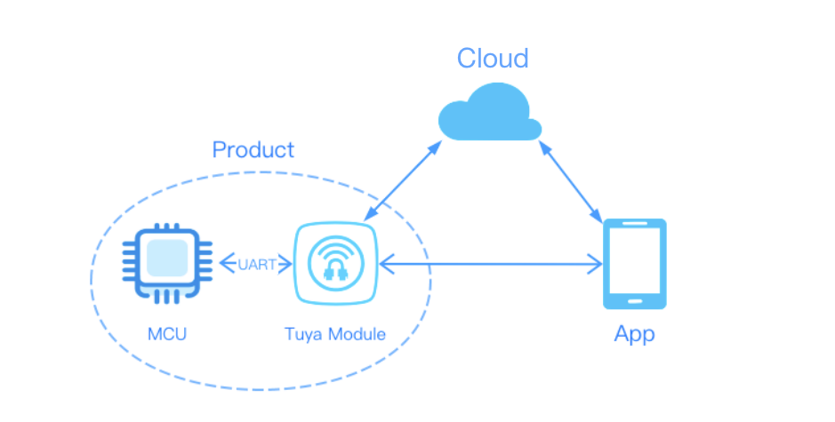
The Wi-Fi module is connected to the cloud through a router without a gateway, which means you can provide users with fast and easy interaction with smart devices. The following block diagram shows how communication works.
Development process
Tuya Developer Platform provides self-service development services, allowing you to complete IoT product development in one place, including product creation, hardware debugging, software development, connectivity verification, and functionality debugging.
Step 1: Create product
Create a Wi-Fi product on the Tuya Developer Platform and define the required function. For more information, see Product Creation.
-
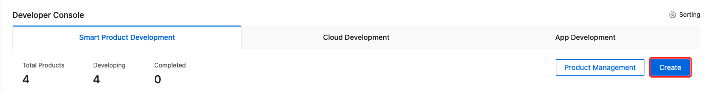
Log in to the Tuya Developer Platform. Click Create.
-
Select the desired product category. Choose Wi-Fi for Protocol.
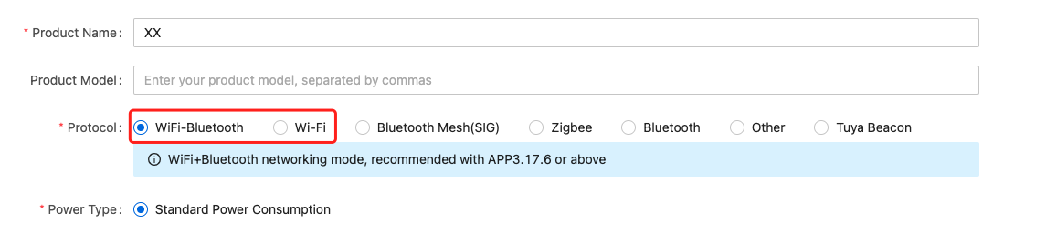
Wi-Fi and Bluetooth combo protocol is subject to the Tuya Wi-Fi serial communication protocol. It supports both Wi-Fi and Bluetooth connectivity. Wi-Fi acts as the primary connectivity protocol. Bluetooth is adopted for device pairing, or device control when the internet is disconnected and LAN is connected.
Some product category supports the option for low power consumption. For mains-powered products, choose standard power. For battery-powered products, choose low power. Power consumption determines the network modules and firmware available for selection.
-
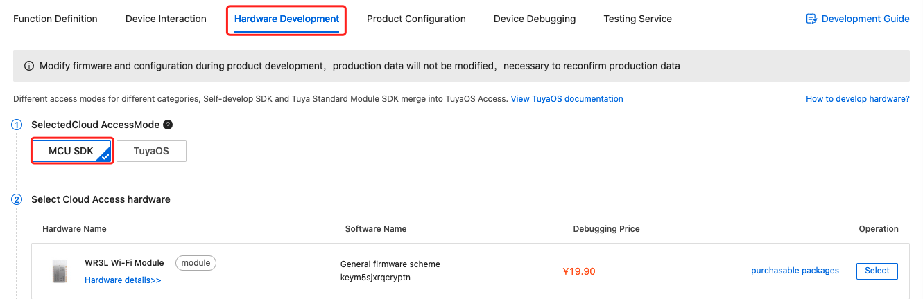
After you create a product, you can configure the function, panel, module, and firmware based on your requirements. Then, download the MCU SDK accordingly.
-
The Wi-Fi modules are broken down into three series:
- WR1/WBR1/WBR1D: indicates series 1. They are the common models with relatively large assembly and support the PCB antenna and external antenna. Modules supporting external antenna take the name format of
Model Name-IPEX. - WR2/WBR2/WBR2D: indicates series 2. They use DIP assembly and are suitable for space-constrained products.
- WR3/WBR3/WBR3D: indicates series 3. They are the common models and smaller than series 1.
- CBU: indicates series U. They support DIP and SMT assembly.
For more information, see Solution Center.
- WR1/WBR1/WBR1D: indicates series 1. They are the common models with relatively large assembly and support the PCB antenna and external antenna. Modules supporting external antenna take the name format of
-
After you select the module and firmware, you can purchase modules online and proceed with the PCB layout. For more information about hardware development, see the following documentation:
-
Wi-Fi hardware design guideline
The operating current of the module is within 100 mA on average but the peak current is more than 400 mA with a duration of microseconds. The consideration for electricity allowance is required in your circuit design.
Step 2: Debug hardware
Use Tuya’s Module Debugging Assistant to verify the functionality of the Wi-Fi module. This debugger supports two modes, MCU simulation mode and module simulation mode. In the MCU simulation mode, the computer can simulate the MCU. This allows you to directly verify the hardware functionality of the module without software development up front.
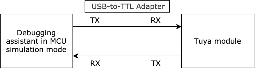
In the MCU simulation mode, the debugging assistant simulates the MCU and responds to commands from the module. After you pair the module with the mobile app, you can test whether the module can receive and send data point (DP) data correctly. This section briefly describes how to test data communication by using the debugging assistant. For more information, see Module Debugging Assistant.
-
Set up the peripheral circuit according to the minimal system schematics.
If you want to perform a simple test, you can use the jump wire to set up the testing environment.
-
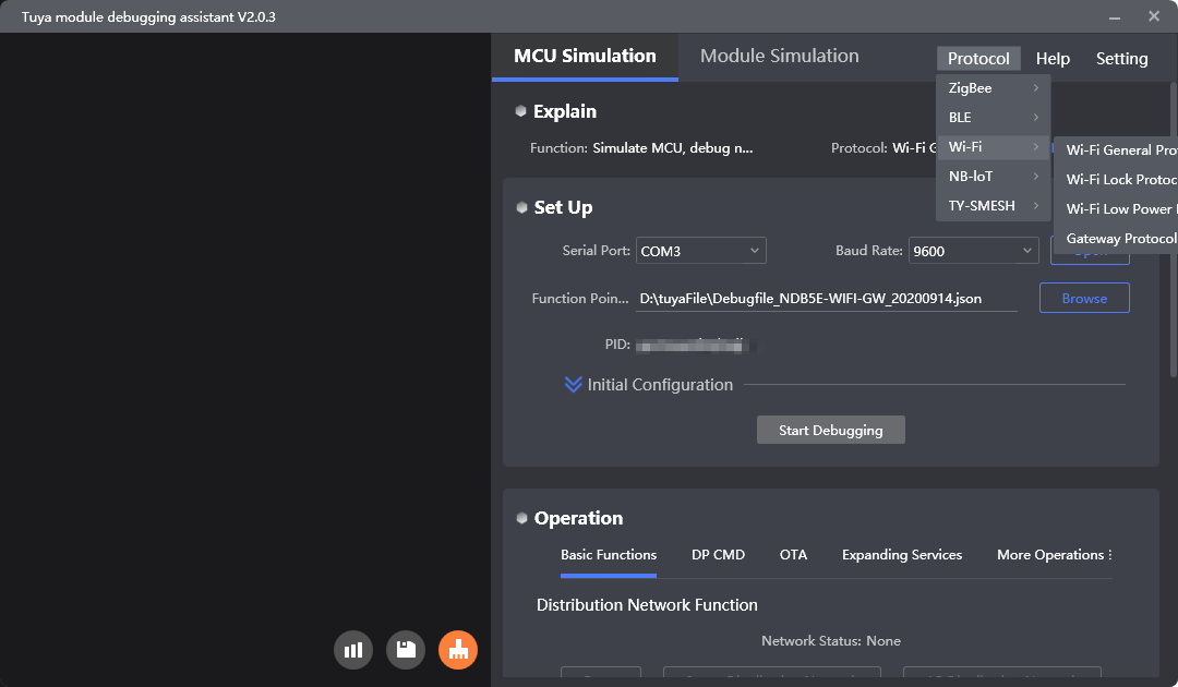
Open the debugging assistant and import the debugging file. Click MCU Simulation and choose Wi-Fi General Protocol for Protocol.
-
Connect the module to your computer by using a USB to TTL converter. Set the Serial Port and Baud Rate. Click Open and then Start Debugging to start the data communication.
The module constantly sends heartbeats to the MCU after power-on. It will start initialization on receiving the correct response from the MCU. If the module does not send data after power-on, you should check whether the peripheral circuit of the module works as expected.
-
Reset the module to enter pairing mode.
The module supports both EZ mode and AP mode for pairing. Press the rest button to toggle between these two modes. For more information about two Wi-Fi pairing modes, go to Help Center.
-
Pair the module with the mobile app as instructed by the guide.
Step 3: Develop software
In the previous testing step, the left interface of Tuya’s debugging assistant shows you the data communication between the MCU and the module. For more information about communication logic, see the protocol documentation included in the development document. The protocol consists of the basic protocol and the function protocol.
-
The basic protocol is product-neutral and shared by the modules. It consists of commands for module initialization and extended functions. For more information, see Serial Communication Protocol.
-
The function protocol works to report and send commands based on the basic protocol and specifies the DP data format.
Tuya provides two methods to implement the communication between your MCU and Tuya’s module.
-
Interface with the protocol yourself
If your MCU does not have sufficient resources or porting SDK is not feasible, you can interface the serial protocol yourself. For more information, see Serial Communication Protocol.
-
Port the MCU SDK
If your MCU has sufficient resources, we recommend you port the MCU SDK for efficiency purposes. The MCU SDK is written in C language. You can directly import it to your project. The MCU SDK requires the following MCU hardware resources:
-
4 KB flash memory.
-
About 100 bytes of the RAM are required, depending on the data length of the data point (DP). If you enable OTA updates, it must be greater than 260 bytes.
-
The 9-level nested function is adopted. The functions in the SDK can be your reference.
For more information, see Port MCU SDK.
-
Step 4: Verify protocol
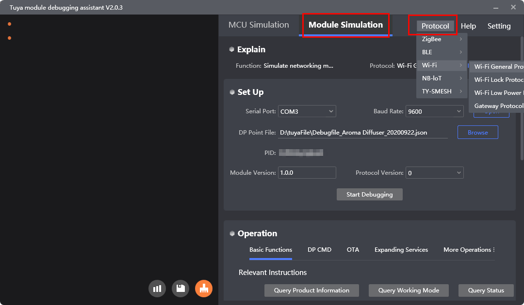
After you port the MCU SDK, you can use the module simulation mode in the debugging assistant to verify the code.
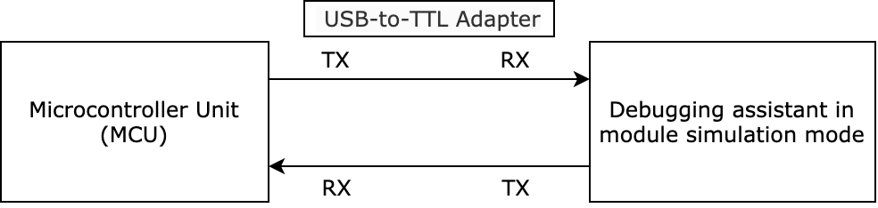
In the module simulation mode, the debugging assistant automatically sends the initial data to the MCU to check whether the communication works properly. An error message will be returned if any issue occurs. After initialization, you can test different functions.
The module simulation mode only verifies the communication between the MCU and the module and does not provide real networking capability. After finishing the test, you can connect the MCU to the actual module and test pairing functionality and specific features.
Step 5: Debug functionality
After the code is verified, you can pair the module with the app and test DP data communication. During the debugging, you can access the following services to troubleshoot issues:
-
You can query device logs by device ID on the Tuya Developer Platform. For more information, see Device Log Service.
-
If the documentation cannot resolve your questions, you can submit a ticket to request technical support. For more information, see Service and Support.
Development resources
Documentation
| Documents | Description |
|---|---|
| Protocol application | It describes the solution for interfacing with Tuya’s Wi-Fi modules, consisting of protocol features description and common troubleshooting questions. |
| MCU SDK Porting | The MCU SDK contains all you need to get started with MCU development, such as functions and sample code. It is automatically generated based on the product features defined on the Tuya Developer Platform. The documentation describes how to port the MCU SDK to your project. |
| Module datasheet | It describes the types of network modules in terms of protocols, naming rules, features, and development methods. |
| Hardware design guidelines | It describes the hardware design for implementing the UART communication between Tuya’s network modules and microcontrollers. |
| Module Debugging Assistant | Tuya Module Debugging Assistant is an all-in-one debugger using serial communication. It can simulate both the network modules and microcontrollers and support a bunch of protocols to help you perform a comprehensive test on your embedded system. |
Routines
Routines for your reference:
Is this page helpful?
YesFeedbackIs this page helpful?
YesFeedback


