Basic Features
This topic describes the basic features in the Wi-Fi generic protocol, including module initialization, device pairing, and two-way data transmission between the device and the cloud, which are essential to make your product IoT-enabled.
- If your MCU does not have sufficient resources or porting SDK is not feasible, you can interface the serial protocol yourself. Note that the basic features must be implemented. Otherwise, your product will not work properly.
- All the protocol examples in this topic are performed on the module debugging assistant. This debugger can help you understand how data transmission works.
Module initialization
Module initialization indicates a process where a module performs the initial configuration with the information sent from the MCU.
Feature description
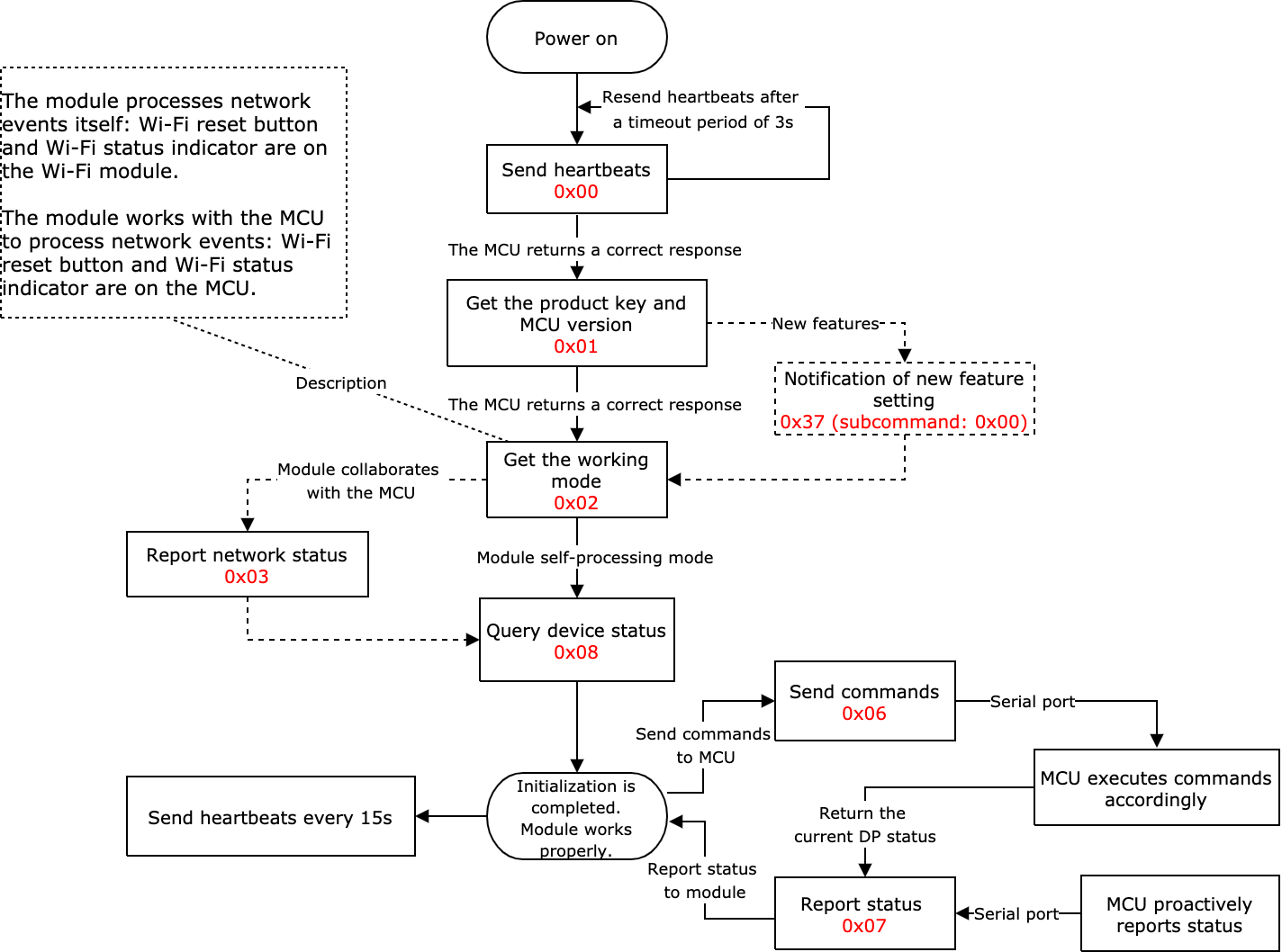
After the module establishes communication with the MCU, it must complete the initialization process before performing pairing with the mobile app, data processing, and extended features. Module initialization includes but is not limited to the following actions:
- Establishing a heartbeat connection with the MCU.
- Getting product information.
- Getting the working mode.
- Reporting the current network status to the MCU (required if the module works with the MCU to process network events).
- Getting device status.
After power on, the module keeps sending heartbeats to the MCU and will not proceed with the initialization process until receiving a correct response from the MCU.
Auto-baud detection
The latest firmware supports automatic baud selection from 9600 or 115200. Automatic baud detection will occur before the first initialization. It is normal to get some garbled text or startup latency. The following describes how auto-baud detection works.
-
The module reads the baud history saved in the flash memory.
-
The module enters the correct initialization process according to whether the baud is detected.
- If baud detected: The module sets the baud to the detected value and sends three heartbeats to the MCU with an interval of one second. If the MCU does not return a response, the module will enter the detection mode again.
- If baud not detected: The module enters the detection mode. It sends two heartbeats at
9600baud and waits for a response from the MCU. Then, it repeats the same heartbeat sending pattern at115200baud. The interval between baud detections can be 300 ms to 400 ms. If the module receives the intended response, it means the correct baud is detected. The detected baud will be used to initialize serial communication and be saved on the flash memory.
Scenarios:
The initialization is triggered after the module is restarted or reset. There can be two situations:
-
Device is not paired: The configuration of the product information and working mode is completed. The module reports the current network status to the MCU and is ready for pairing.
-
Device is paired: The configuration of the product information and working mode is completed. The module is connected to the remembered network and reports the current network status to the MCU. It also requests device status to sync with the mobile app. The MCU needs to return the current status of all DPs to the module.
Commands
The commands used in the initialization process.
- Heartbeat detection:
0x00 - Product information query:
0x01 - Notification of new feature setting:
0x37(subcommand:0x00) - Working mode query:
0x02 - Reporting network status:
0x03
Precondition: The module works with the MCU to process network events. - Device status query:
0x08
Precondition: The device has been paired.
The following describes how each command works.
Heartbeat detection (0x00)
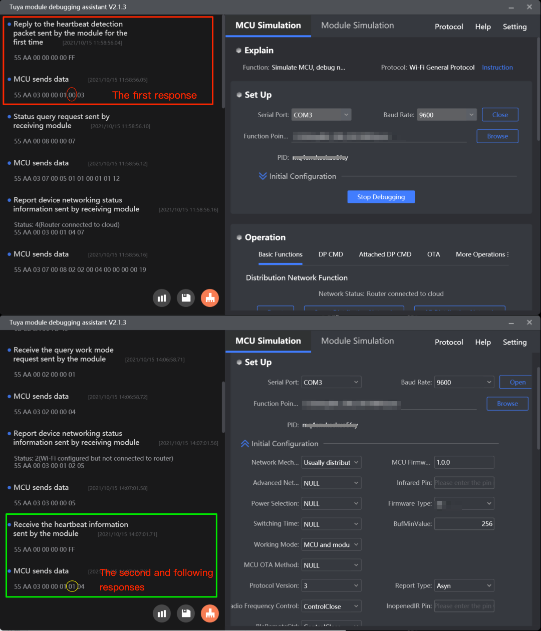
The heartbeat protocol is used to monitor the availability of the MCU, which also serves as one of the important indicators to determine whether a device is offline. Therefore, the MCU must respond to a heartbeat timely. For more information, see Send heartbeats.
- After the first-time heartbeat connection, the module will send a heartbeat to the MCU every 15 seconds. We recommend that the MCU return a response within three seconds after receiving a heartbeat.
- Clear cache after timeout: With an established heartbeat connection, if the module does not receive a response after two consecutive heartbeat packets, it will clear the cached data in the serial buffer if any, and stop serial transmission. For example, the module intends to update the current network status to the MCU but has to stop transmission due to failed heartbeat check. On the MCU side, the result is that this network status notification is missing.
- Restart after timeout: With an established heartbeat connection, if the module does not receive a response after six consecutive heartbeat packets (that is within 90 seconds), it will automatically restart. For a paired device, if a heartbeat connection fails to be established after a restart, the server will declare that this device is offline about three minutes later.
The MCU can determine whether the module works properly by detecting heartbeats. If the module does not send heartbeats at regular intervals, the MCU can use the reset pin to reset the module.
Make sure to properly test the heartbeat connection, which is fundamental to successful serial communication. If your product requires low power, you can use the command 0x25 to turn off the heartbeat detection.
Product information query (0x01)
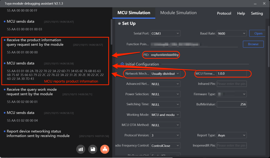
After the MCU responds to a heartbeat, the module will request the production information. The MCU returns the product ID (PID), MCU version, working mode, and optional configuration information. For more information, see Query product information.
If the MCU returns the wrong information, the module will keep sending the request. Check whether the data content and format are correct.
Command example
-
The module sends
55 aa 00 01 00 00 00. -
The MCU returns
55 aa 03 01 00 2a 7b 22 70 22 3a 22 52 4e 32 46 56 41 67 58 47 36 57 66 41 6b 74 55 22 2c 22 76 22 3a 22 31 2e 30 2e 30 22 2c 22 6d 22 3a 30 7d 0c.Field Description ASCII Hexadecimal pProduct ID (PID) "p":"RN2FVAgXG6WfAktU"22 70 22 3a 22 52 4e 32 46 56 41 67 58 47 36 57 66 41 6b 74 55 22vMCU version "v":"1.0.0"22 76 22 3a 22 31 2e 30 2e 30 22mWorking mode of the module "m":022 6d 22 3a 30
Convert ASCII characters and punctuation marks in {"p":"RN2FVAgXG6WfAktU","v":"1.0.0","m":0} to hexadecimal values. To configure additional fields, follow the format and add them to the MCU’s return data.
Field description
| Field | Description | Configuration content | Description |
|---|---|---|---|
m |
Operation mode of the module |
|
|
mt |
Timeout period | Set a timeout period between 3 and 10 minutes for pairing in safe mode and anti-misoperation mode. If you leave this field empty, the period defaults to 3 minutes. | For example, if you set the timeout to five minutes, add "mt":5 to the MCU’s return data. |
n |
Pairing mode | If you leave this field empty, the pairing mode is switched between the Wi-Fi Easy Connect (EZ) mode and the access point (AP) mode.
|
For more information about pairing modes, see Device pairing. |
ir |
Infrared functionality | Used to enable the infrared (IR) feature and notify the module of the IR transmission (TX) pin and IR reception (RX) pin. If you leave this field empty, the IR feature is disabled. If you add "ir":"5.12" to the MCU’s return data, it indicates the IR TX pin is I/O 5 and the IR RX pin is I/O 12. |
If the module works in the self-processing mode, the IR I/Os must not be used for the reset button or the Wi-Fi status indicator. For cross-module I/O configuration, the pin number plus 32 makes the pin number we need. For example, the pin number to be set for PB20 is 52 (20 + 32 = 52). The IR TX pin requires PWM signals. The IR RX pin requires I/O interrupts. For more information about the pin configuration, see the datasheet of your modules. |
low |
Low power mode | Used to enable the low power mode while maintaining a persistent connection. If you leave this field empty, the low power mode is disabled. When a paired device is connected to the router but not executing any commands, its power consumption can be lower than 15 mA on average by reducing the consumption of radio frequency.
|
If you add "low":1 to the MCU’s return data, it indicates enabling low power mode while maintaining a persistent connection. |
vt |
MCU firmware type | Your specified value must match the value of the field Update Channel that appears when you add firmware on the Tuya Developer Platform. The MCU firmware type defaults to 9. You can set a value between 10 and 19 to specify a firmware type. |
The value of vt you specified in the SDK must be consistent with the value of Update Channel specified on the Tuya Developer Platform. Otherwise, the device cannot receive OTA updates or receives the wrong OTA updates. |
Notification of new feature setting (0x37, subcommand 0x00)
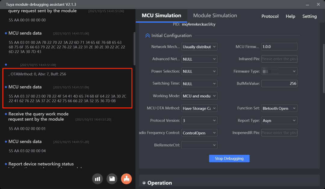
After the product information query, the module will send 0x02 to get the working mode. The MCU can use this command to send new features to the module for configuration, such as feature enablement, IR indicator, buffer size, and OTA updates. For more information, see Notify new feature configuration.
If no new feature configuration is required, the MCU does not need to send this command. If there is a new feature to be set, the MCU needs to send this command to the module after power on or a restart.
Command example
- The module sends
55 aa 00 01 00 00 00. - The MCU returns
55 AA 03 37 00 27 00 7B 22 6D 63 75 5F 6F 74 61 22 3A 30 2C 22 61 62 76 22 3A 31 2C 22 69 72 22 3A 37 2C 22 62 75 66 22 3A 32 35 36 7D 42.
| Field | Description | ASCII | Hexadecimal |
|---|---|---|---|
mcu_ota |
Specifies whether an MCU has a scratchpad. This field only applies to HomeKit accessories currently.
|
"mcu_ota":0 |
22 6D 63 75 5F 6F 74 61 22 3A 30 |
abv |
Enables features. Bit0: Bluetooth connection notification (applies to Wi-Fi and Bluetooth combo modules).
|
"abv":1 |
22 61 62 76 22 3A 31 |
ir |
Sets the GPIO pin used for IR status indicator in the module self-processing mode. The data content follows the definition of the command 0x02. |
"ir":7 |
22 69 72 22 3A 37 |
buf |
The maximum buffer size of the MCU serial port. The minimum buffer is 256 bytes. | "buf":256 |
22 62 75 66 22 3A 32 35 36 |
- The fields of this command will be added as the service is extended.
- You can refer to the implementation of query product information in the MCU SDK and implement the command of notification of new feature setting yourself.
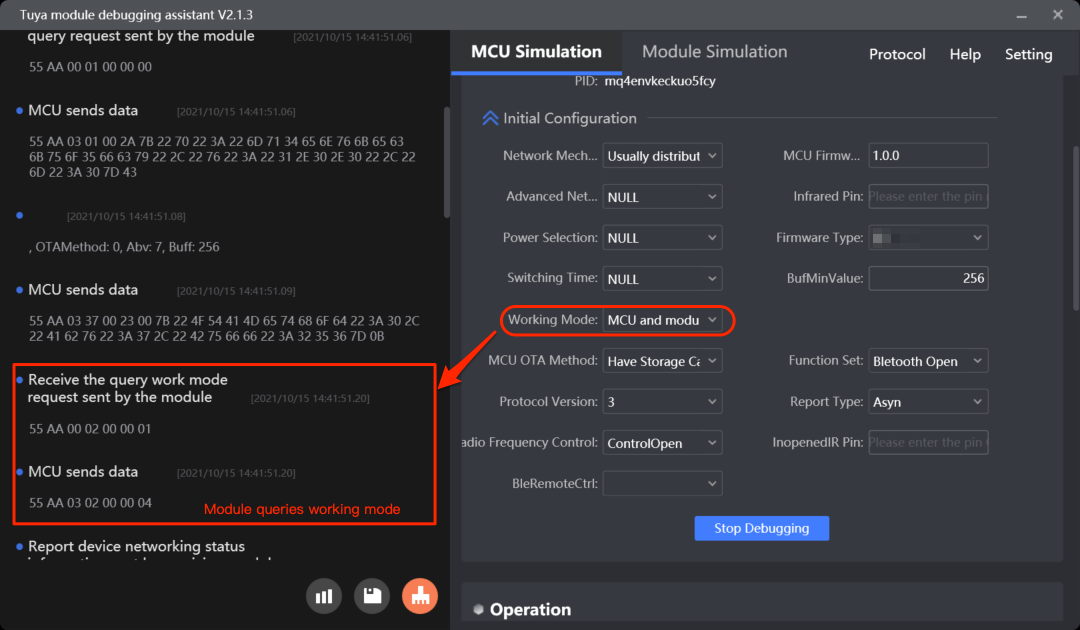
Working mode query (0x02)
After the product information query, the module will send 0x02 to get the working mode. For more information, see Query working mode. The working mode indicates how the network status is indicated and the way to trigger module reset. The Wi-Fi module can work in the following two modes.
-
The MCU works with the module to process network events.
-
Reset method: The MCU sends a reset command to enable the module to enter pairing mode.
-
Network status indication: The module sends the current network status to the MCU through serial communication. The MCU controls the LED to indicate network status accordingly.
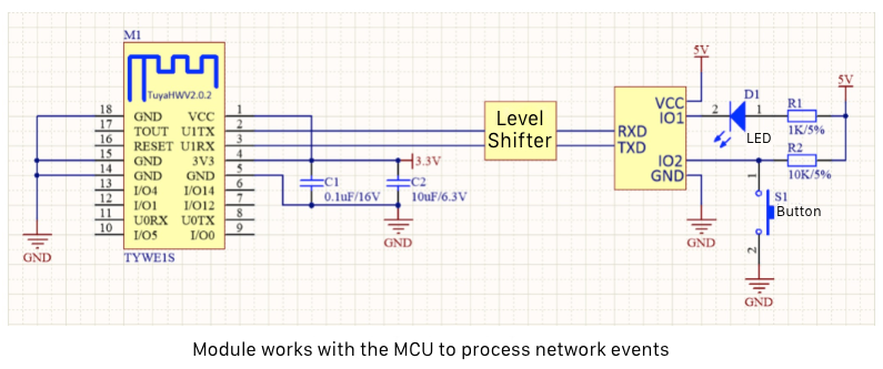
-
-
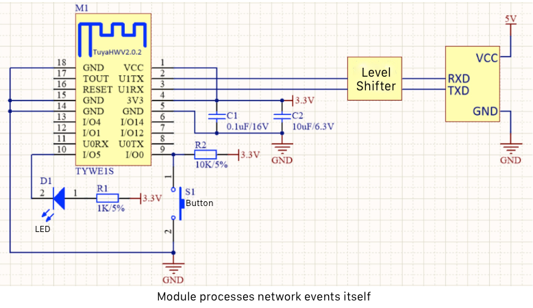
The module processes network events itself.
- Reset method: When the module detects a low level on the reset pin for more than five seconds, it will trigger a reset action. The commands in the following table specify the GPIO pins of the LED indicator and the reset button.
- Network status indication: The GPIO pin on the module drives the LED indicator to indicate the network status. For more information, see Serial Communication Protocol.
| Type | Header | Version | Command | Data length | Data | Checksum |
|---|---|---|---|---|---|---|
| Command sent from module | 0x55aa | 0x00 | 0x02 | 0x0000 | None | 0x01 |
| Command returned from MCU (module works with MCU on network events) | 0x55aa | 0x03 | 0x02 | 0x0000 | None | Checksum |
| Command returned from MCU (module processes network events itself) | 0x55aa | 0x03 | 0x02 | 0x0002 | The first byte represents the GPIO pin used to indicate Wi-Fi status. The second byte represents the GPIO pin used to reset the Wi-Fi network. |
Checksum |
- If the module processes network events itself, the steps of reporting network status and network reset in the initialization process are not needed. This means that a network reset can only be made by pulling down the reset pin.
- After a reset, the pairing mode switches between EZ mode and AP mode, similar to the command of resetting Wi-Fi connection (
0x04).
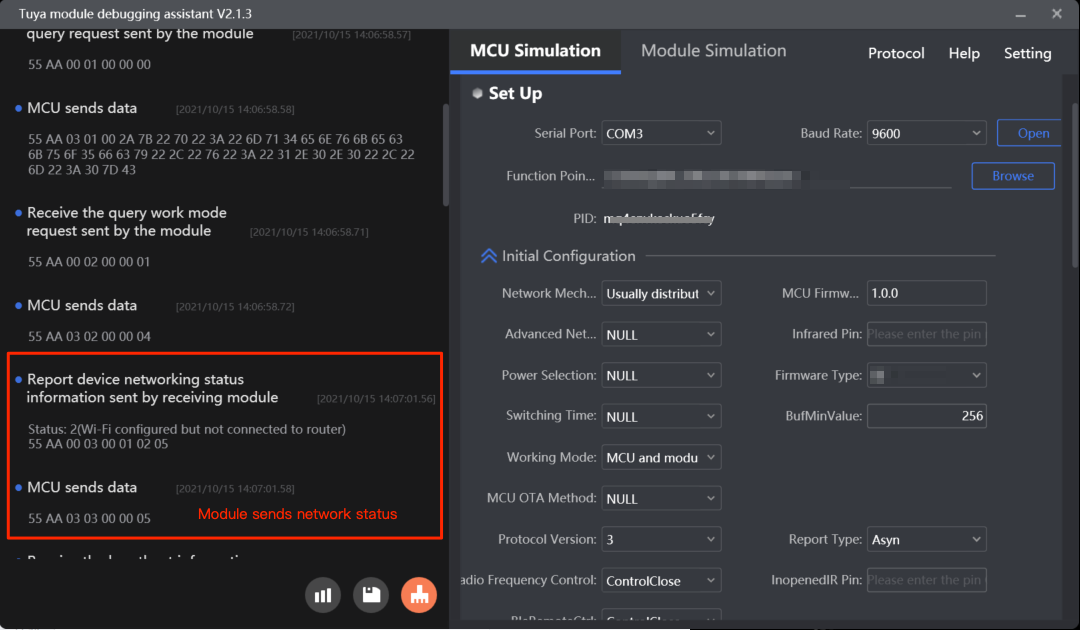
Reporting network status (0x03)
This command is used only when the module works with the MCU to process network events.
After getting the working mode, the module will report the current network status to the MCU. The MCU can control the LED indicator to indicate the network status accordingly. For more information, see Report network status.
When the module detects that the device is restarted or the network connection is changed, it will proactively send the current network status to the MCU so that the MCU can control the LED to provide the correct network status indication. It is recommended that the setting of LED activity is the same as the one used when the module processes network events itself. For example, the LED blinks every 250 ms in status 1.
Device status query (0x08)
For more information, see Query DP status. The module sends device status queries in the following situations:
- The module is powered on for the first time after being paired. If the module processes network events itself, it queries device status after it gets the working mode in the initialization process. If the module works with the MCU to process the network event, it queries device status after it reports network status to the MCU in the initialization process.
- For the paired module, when it detects the MCU is restarted or disconnected and then goes online, it sends status queries.
The MCU needs to report the current status of all DPs through 0x07 so that the module can sync with the mobile app.
Protocol examples
-
Heartbeat connection
-
Product information query
-
Notification of new feature setting
-
Working mode:
The module works with the MCU to process network events.
-
Report network status
-
Device status query
MCU SDK sample code
Heartbeat connection
heat_beat_check() in system.c is used for the MCU to respond to heartbeats. The process is as follows:
-
The serial data handler
data_handle()receives a heartbeat. -
The MCU calls
heat_beat_check()to respond to a heartbeat. It returns0x00on its first response to a heartbeat and returns0x01on later heartbeat checks./** * @brief Data frame processing * @param[in] {offset} The start bit * @return Null */ void data_handle(unsigned short offset) { …… case HEAT_BEAT_CMD: // Send a heartbeat. heat_beat_check(); // Respond to a heartbeat. break; ...... }/** * @brief Heartbeat detection * @param Null * @return Null */ static void heat_beat_check(void) { unsigned char length = 0; static unsigned char mcu_reset_state = FALSE; if(FALSE == mcu_reset_state) { length = set_wifi_uart_byte(length, FALSE); // The MCU returns 0x00 on its first response to a heartbeat. mcu_reset_state = TRUE; }else { length = set_wifi_uart_byte(length, TRUE); // The MCU returns 0x01 on later heartbeat checks. } wifi_uart_write_frame(HEAT_BEAT_CMD, MCU_TX_VER, length); }data_handle()is used to receive and process data from the module.wifi_uart_write_frame()is used for the MCU to send serial data to the module.
Product information query
product_info_update() in system.c is used for the MCU to return product information. The process is as follows:
-
The serial data handler
data_handle()receives a product information query. -
The MCU calls
product_info_update()to report product information.You can enable or modify corresponding macros to report product information such as PID and MCU version number or other fields you need.
#define PRODUCT_KEY "orxyzazpfw******"    // The 16-digit product ID (PID) is the unique identifier of the product you have created on the Tuya Developer Platform.
#define MCU_VER "1.0.0"         // The MCU firmware version number, which must be changed to the new one after MCU updates.
/* You can only select one operation mode from the three available modes. Anti-misoperation is recommended. */
//#define CONFIG_MODE     CONFIG_MODE_DEFAULT             // Active pairing, the default mode.
//#define CONFIG_MODE     CONFIG_MODE_LOWPOWER            // Passive pairing, the safe mode.
#define CONFIG_MODE     CONFIG_MODE_SPECIAL             // Anti-misoperation mode.

/*  Set a timeout period between 3 and 10 minutes for pairing in safe mode and anti-misoperation mode. If you leave this macro commented out, the period defaults to 3 minutes.   */
//#define CONFIG_MODE_DELAY_TIME    10         // Set a timeout period, in minutes.

/*  Set the pairing mode. If you leave this macro commented out, the pairing mode will be switched between EZ mode and AP mode. */
//#define CONFIG_MODE_CHOOSE        0         //  EZ mode and AP mode coexist, corresponding to network status `0x06`.
//#define CONFIG_MODE_CHOOSE        1         //  Only AP mode supported.

/*   You can enable the infrared (IR) feature and notify the module of the IR transmission (TX) pin and IR reception (RX) pin. If you leave this field empty, the IR feature is disabled.  */
//#define ENABLE_MODULE_IR_FUN                  // Enable the infrared feature.
#ifdef ENABLE_MODULE_IR_FUN
#define MODULE_IR_PIN_TX      5       // The IR transmission pin.
#define MODULE_IR_PIN_RX      12      // The IR reception pin.
#endif

/*  You can enable the low power mode while maintaining a persistent connection. If you leave this field empty, the low power mode is disabled. */
//#define LONG_CONN_LOWPOWER        0         //  Disable low power mode.
//#define LONG_CONN_LOWPOWER        1         // Enable low power mode.
void data_handle(unsigned short offset) { …… case PRODUCT_INFO_CMD: // Query product information. product_info_update(); break; ...... }/** * @brief Send product information * @param Null * @return Null */ static void product_info_update(void) { unsigned char length = 0; unsigned char str[10] = {0}; length = set_wifi_uart_buffer(length, "{\"p\":\"", my_strlen("{\"p\":\"")); length = set_wifi_uart_buffer(length,(unsigned char *)PRODUCT_KEY,my_strlen((unsigned char *)PRODUCT_KEY)); // Write PID to `wifi_uart_buffer`. length = set_wifi_uart_buffer(length, "\",\"v\":\"", my_strlen("\",\"v\":\"")); length = set_wifi_uart_buffer(length,(unsigned char *)MCU_VER,my_strlen((unsigned char *)MCU_VER)); // Write MCU version number to `wifi_uart_buffer`. length = set_wifi_uart_buffer(length, "\",\"m\":", my_strlen("\",\"m\":")); length = set_wifi_uart_buffer(length, (unsigned char *)CONFIG_MODE, my_strlen((unsigned char *)CONFIG_MODE)); // Write working mode to `wifi_uart_buffer`. #ifdef CONFIG_MODE_DELAY_TIME sprintf((char *)str,",\"mt\":%d",CONFIG_MODE_DELAY_TIME); length = set_wifi_uart_buffer(length, str, my_strlen(str)); // Write pairing timeout period to `wifi_uart_buffer`. #endif #ifdef CONFIG_MODE_CHOOSE sprintf((char *)str,",\"n\":%d",CONFIG_MODE_CHOOSE); length = set_wifi_uart_buffer(length, str, my_strlen(str)); // Write pairing mode to `wifi_uart_buffer`. #endif #ifdef ENABLE_MODULE_IR_FUN sprintf((char *)str,",\"ir\":\"%d.%d\"",MODULE_IR_PIN_TX,MODULE_IR_PIN_RX); length = set_wifi_uart_buffer(length, str, my_strlen(str)); // Write IR capability to `wifi_uart_buffer`. #endif #ifdef LONG_CONN_LOWPOWER sprintf((char *)str,",\"low\":%d",LONG_CONN_LOWPOWER); length = set_wifi_uart_buffer(length, str, my_strlen(str)); // Write low power mode to `wifi_uart_buffer`. #endif length = set_wifi_uart_buffer(length, "}", my_strlen("}")); wifi_uart_write_frame(PRODUCT_INFO_CMD, MCU_TX_VER, length); }
Working mode query
get_mcu_wifi_mode() in system.c is used for the MCU to send the working mode to the module. The process is as follows:
-
The serial data handler
data_handle()receives a working mode query. -
Call
get_mcu_wifi_mode()to report the working mode to the module.You can enable or disable
WIFI_CONTROL_SELF_MODEto set the working mode. If you use the module self-processing mode, you need to set the reset pin and network status LED pin.//#define WIFI_CONTROL_SELF_MODE // Set the reset pin and LED indicator if the module processes network events itself. If you use an external reset button or LED indicator, disable this macro. #ifdef WIFI_CONTROL_SELF_MODE // The module processes network events itself. #define WF_STATE_KEY 14 // The indicator for network status. Set it according to your circuit. #define WF_RESERT_KEY 0 // The button for Wi-Fi module reset. Set it according to your circuit. #endifvoid data_handle(unsigned short offset) { …… case WORK_MODE_CMD: // Query the working mode. get_mcu_wifi_mode(); break; ...... }/** * @brief Query the working mode * @param Null * @return Null */ static void get_mcu_wifi_mode(void) { unsigned char length = 0; #ifdef WIFI_CONTROL_SELF_MODE // The module self-processing mode. You need to configure the reset pin and network status LED pin. length = set_wifi_uart_byte(length, WF_STATE_KEY); length = set_wifi_uart_byte(length, WF_RESERT_KEY); #else //No need to process data #endif wifi_uart_write_frame(WORK_MODE_CMD, MCU_TX_VER, length); }
Network status query
mcu_get_wifi_work_state() in mcu_api.c is used for the MCU to receive the network status. The process is as follows:
-
If the module works with the MCU to process network events,
data_handle()is used for the MCU to receive network status from the module and assign the received value towifi_work_state. -
The MCU can proactively call
mcu_get_wifi_work_state()and control the configured component to indicate the network status accordingly.//#define WIFI_CONTROL_SELF_MODE // Set the reset pin and LED indicator if the module processes network events itself. If you use an external reset button or LED indicator, disable this macro. #ifdef WIFI_CONTROL_SELF_MODE // The module processes network events itself. #define WF_STATE_KEY 14 // The indicator for network status. Set it according to your circuit. #define WF_RESERT_KEY 0 // The button for Wi-Fi module reset. Set it according to your circuit. #endifvoid data_handle(unsigned short offset) { …… #ifndef WIFI_CONTROL_SELF_MODE case WIFI_STATE_CMD: // Report network status. wifi_work_state = wifi_data_process_buf[offset + DATA_START]; // Get the network status. wifi_uart_write_frame(WIFI_STATE_CMD, MCU_TX_VER, 0); ...... }/** * @brief The MCU proactively requests the current network status. * @param Null * @return wifi work state * - SMART_CONFIG_STATE: Pairing in EZ mode. * - AP_STATE: Pairing in AP mode. * - WIFI_NOT_CONNECTED: The Wi-Fi network is set up, but the device is not connected to the router. * - WIFI_CONNECTED: The Wi-Fi network is set up, and the device is connected to the router. * - WIFI_CONN_CLOUD: The device is connected to the cloud. * - WIFI_LOW_POWER: The device is in low power mode. * - SMART_AND_AP_STATE: EZ mode and AP mode coexist. * @note If the module processes network events itself, the MCU does not need to call this function. */ unsigned char mcu_get_wifi_work_state(void) // The MCU proactively calls this function to request the current network status. { return wifi_work_state; }
Report status of all DPs
all_data_update() in protocol.c is used for the MCU to report the status of all DPs. The process is as follows:
-
The serial data handler
data_handle()receives device status query. -
The MCU calls
all_data_update()to report the status of all DPs to the module for sync with the mobile app.The MCU should call the correct function in
all_data_update()according to the data type of a DP. For example, it callsmcu_dp_bool_update()to report the status of a Boolean DP, and the parameters are the corresponding DP ID and DP status data.mcu_dp_value_update()is for DPs of value type,mcu_dp_enum_update()is for DPs of enum type, and so on.void data_handle(unsigned short offset) { …… case STATE_QUERY_CMD: // Query device status. all_data_update(); break; ...... }/** * @brief Upload the status of all DPs to sync with the app. * @param Null * @return Null * @note The device status reporting function is intended to be implemented by you. */ void all_data_update(void) { #error "Complete the example of two data transfer types and delete this line." /* // This code is automatically generated. You need to edit it based on the actual DPs. mcu_dp_bool_update(DPID_SWITCH,current on/off status); // Report Boolean data mcu_dp_value_update(DPID_PM25,current PM2.5); // Report value data mcu_dp_enum_update(DPID_MODE,current mode); // Report enum data mcu_dp_value_update(DPID_FILTER_LIFE,current filter life level); // Report value data mcu_dp_bool_update(DPID_ANION,current anion status); // Report Boolean data mcu_dp_value_update(DPID_COUNTDOWN_LEFT,time remaining of current countdown); // Report value data */ }
Device pairing
The MCU sends a pairing command to the module or pulls down the reset pin to enable the module to enter pairing mode. The module will communicate and pair with the mobile app (such as Tuya app) so that it can be connected to the cloud. This section describes how to enter pairing mode as well as the pairing modes.
Feature description
- Access point (AP) mode: also called hotspot mode. In module self-processing mode, the LED indicator blinks slowly to indicate pairing in AP mode. After the mobile app is connected to the Wi-Fi broadcast from the device to be paired, it sends the SSID and password of the router and the token to the module. Then, the module can get and use the information to connect to the router and the cloud. The AP mode is reliable and can provide a high pairing success rate.
- EZ mode: also called Wi-Fi Easy Connect. In module self-processing mode, the LED indicator blinks quickly to indicate pairing in EZ mode. The mobile app broadcasts the SSID and password of the router, which will be forwarded by the router. Then, the module can get and use the information to connect to the router and the cloud. The EZ mode is easy to operate but less reliable than AP mode.
- Bluetooth pairing (supported by Wi-Fi and Bluetooth combo devices): The module broadcasts messages via Bluetooth. The mobile app can connect to the module over Bluetooth and then send the SSID and password of the router to the module. This way, the module uses the information to connect to the router and the cloud. Bluetooth pairing provides fast device discovery and a reliable pairing process. For the combo devices, the Bluetooth pairing is turned on by default.
How to set pairing mode
- Pairing mode: You can set the pairing mode to AP mode only or coexistence of AP mode and EZ mode with the
nfield in the product information. - Pairing timeout: You can set a timeout period with the
mtfield in the product information if you choose the passive pairing mode or anti-misoperation mode. After pairing times out, the module will enter low power mode.
Only the module enters pairing mode can the mobile app discover the device and pair with it. For more information about pairing with the Tuya app, see User Guide. If you also develop with the Smart App SDK, pairing via serial port might be used. For more information, see Device Pairing.
To pair with a mobile app, the module must enter pairing mode first, which can be one of the following three states.
- Status 1: Pairing in EZ mode.
- Status 2: Pairing in AP mode.
- Status 7: EZ mode and AP mode coexist.
For more information, see Report network status.
Two pairing triggers are available depending on the working mode.
- The MCU works with the module to process network events: The MCU sends a reset command to enable the module to enter pairing mode. Generally, products are designed with a physical reset button, so that pressing the reset button can trigger a reset command sent to the module.
- The module processes network events itself: When the module detects a low level on the reset pin for more than five seconds, it will trigger a reset action to enter pairing mode.
Commands
The commands used in the pairing process.
- Reset Wi-Fi connection:
0x04 - Reset Wi-Fi connection and select pairing mode:
0x05
- The following information applies when the MCU works with the module to process network events.
- You can choose a command between
0x04and0x05. It is recommended to choose0x04because both AP mode and EZ mode need to be implemented to better handle different network conditions. You can customize how the pairing mode is triggered and distinguish between pairing modes by quick and slow LED blinking. - One successful reset interaction through the command
0x04or0x05is good to enable the module to enter pairing. The MCU should not send0x04and0x05at the same time.
The following describes how each command works.
Reset Wi-Fi connection (0x04)
Resetting Wi-Fi network can enable the module to enter pairing mode. For more information, see Reset Wi-Fi connection. After receiving the reset command 0x04, the module will enter pairing mode or switch to the other pairing mode. The pairing mode defaults to EZ mode and later switches between AP mode and EZ mode after each reset.
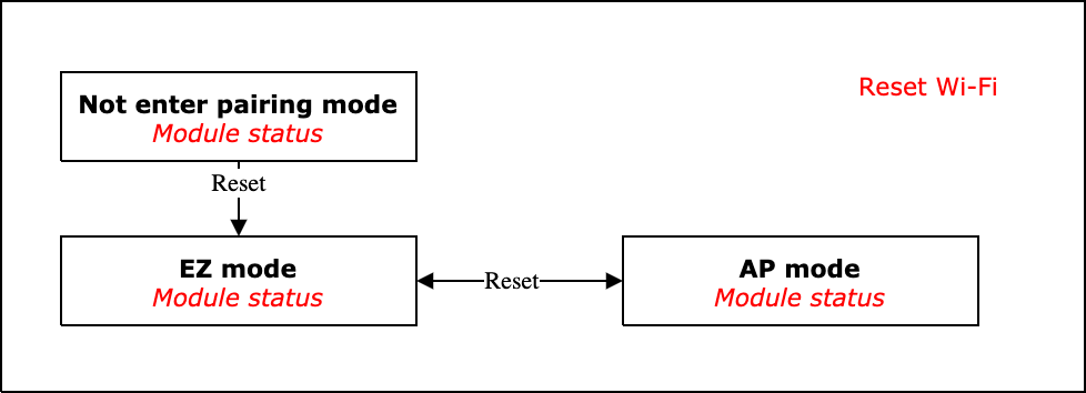
You can set the pairing mode to AP mode only or coexistence of AP mode and EZ mode with the n field in the product information.
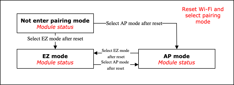
Reset Wi-Fi connection and select pairing mode (0x05)
You can specify which pairing mode the module enters by the parameters the MCU sends. Basically, this command 0x05 functions the same way as 0x04 does and the difference lies in that the 0x05 supports pairing mode specification. For more information, see Reset Wi-Fi and select pairing mode.
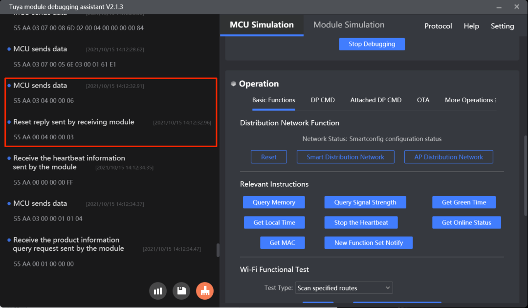
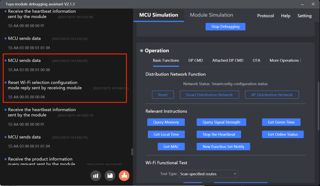
Protocol examples
Tuya’s Module Debugging Assistant can help you understand how data transmission works. The following protocol examples are performed on this debugger.
-
Reset Wi-Fi connection
-
Reset Wi-Fi connection and select pairing mode
MCU SDK sample code
Reset Wi-Fi connection
mcu_reset_wifi() in mcu_api.c is used to send a network reset command to the module. The process is as follows:
-
You can define when to initiate pairing so that the MCU will proactively call
mcu_reset_wifi()then. -
In
data_handle(), if the MCU receives the module’s response to the reset command, it activatesreset_wifi_flag. The value ofreset_wifi_flagreturned bymcu_get_reset_wifi_flag()determines whether the reset succeeds./** * @brief The MCU proactively sends a network reset command to the module. * @param Null * @return Null * @note 1: The MCU proactively calls the network reset function and gets the result through `mcu_get_reset_wifi_flag()`. * 2: If the module processes network events itself, the MCU does not need to call this function. */ void mcu_reset_wifi(void) { reset_wifi_flag = RESET_WIFI_ERROR; wifi_uart_write_frame(WIFI_RESET_CMD, MCU_TX_VER, 0); // The MCU sends the reset command `0x04`. }void data_handle(unsigned short offset) { …… case WIFI_RESET_CMD: // Reset Wi-Fi connection. reset_wifi_flag = RESET_WIFI_SUCCESS; // The module returns successful reset. break; …… }/** * @brief The MCU queries whether the network reset succeeded. * @param Null * @return The flag that indicates the result of network reset. * - 0(RESET_WIFI_ERROR): failure * - 1(RESET_WIFI_SUCCESS): success * @note 1: The MCU calls this function to query the result after proactively calling `mcu_reset_wifi()`. * 2: If the module processes network events itself, the MCU does not need to call this function. */ unsigned char mcu_get_reset_wifi_flag(void) // The MCU calls this function to query the result of network reset. { return reset_wifi_flag; }
Reset Wi-Fi connection and select pairing mode
mcu_set_wifi_mode() in mcu_api.c is used to send a network reset command to the module and direct the module to enter the specified pairing mode. The process is as follows:
-
You can define when to initiate pairing and which pairing mode the module enters so that the MCU will proactively call
mcu_set_wifi_mode()then. -
In
data_handle(), if the MCU receives the module’s response to the reset command, it activatesset_wifimode_flag. The value ofset_wifimode_flagreturned bymcu_get_wifimode_flag()determines whether the reset succeeds./** * @brief The MCU sets the pairing mode. * @param[in] {mode} Specified pairing mode. * @ref 0(SMART_CONFIG): EZ mode * @ref 1(AP_CONFIG): AP mode * @return Null * @note 1: The MCU proactively calls this function. * 2: If the return value of `set_wifi_config_state` is TRUE, it indicates the pairing mode is set successfully. * 3: If the module processes network events itself, the MCU does not need to call this function. */ void mcu_set_wifi_mode(unsigned char mode) { unsigned char length = 0; set_wifimode_flag = SET_WIFICONFIG_ERROR; length = set_wifi_uart_byte(length, mode); // Write the specified pairing mode, AZ mode or AP mode. wifi_uart_write_frame(WIFI_MODE_CMD, MCU_TX_VER, length); // The MCU sends the network reset command and chooses the specified pairing mode. }void data_handle(unsigned short offset) { …… case WIFI_MODE_CMD: // Reset network and choose the pairing mode. set_wifimode_flag = SET_WIFICONFIG_SUCCESS; // Successful operation. break; …… }/** * @brief The MCU queries whether the pairing mode is set successfully. * @param Null * @return Wi-Fi mode flag * - 0(SET_WIFICONFIG_ERROR): failure * - 1(SET_WIFICONFIG_SUCCESS): success * @note 1: The MCU calls this function to query the result after proactively calling `mcu_set_wifi_mode()`. * 2: If the module processes network events itself, the MCU does not need to call this function. */ unsigned char mcu_get_wifimode_flag(void) // The MCU calls this function to query the result of network reset. { return set_wifimode_flag; }
Data transfer
Feature description
The remote control works based on the two-way communication between the device and the cloud. The device reports status to the cloud and the cloud sends control commands to the device. This section describes how the two-way data transfer works.
During debugging, if you modify the DP of a product on the Tuya Developer Platform, you must remove this product from the mobile app and pair it again. Otherwise, errors might occur.
Report status to the cloud
- Principle: The MCU reports the DP whose status is updated, except for the response to the command
0x08. - Filter out duplicates: When the MCU reports status with
0x07, if there is sequential identical data of the same DP, the module will only include it once to report. However, in some situations, such as tables, if you want such duplicate data to be reported, you have two solutions.- Backend configuration: Contact your account manager or submit a service ticket to request syntax configuration for specific DPs. The new configuration will take effect after you pair the device again.
- Use the synchronous reporting command
0x22: The filter rule does not apply to the data reported synchronously. For more information, see Report status (synchronous).
Try to avoid frequent status reporting. Otherwise, unknown errors might occur, such as devices getting offline or data loss. Reporting frequency of less than one frame per second is recommended.
Data flow
Bi-directional communication between the cloud or the mobile app and devices.
-
Send data: The mobile app sends data to the cloud, then the cloud sends it to the module, and finally, the module sends it to the MCU through serial communication.
-
Report data: The MCU sends data to the module through serial communication, then the module reports it to the cloud, and finally, the cloud sends it to the mobile app.
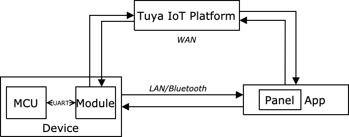
The above data flow works over a WAN, which means a device must be paired and connected to the cloud. If a device works over a LAN or Bluetooth connection, it can communicate with the mobile app in a short range.
-
Device control over a LAN: A device has been paired with the mobile app. The connected router has no internet access so the device and the mobile app communicate over a LAN.
-
Device control over Bluetooth: applies to Wi-Fi and Bluetooth combo devices. A device has been paired with the mobile app. Both the LAN and WAN are disconnected so the device and the mobile app communicate over Bluetooth.
After a device is disconnected from the LAN and WAN, the time taken to connect to Bluetooth depends on the types of firmware, which generally can be within two minutes.
Commands
The commands used in the pairing process.
- Send commands:
0x06 - Report status asynchronously:
0x07
The following describes how each command works.
Send commands (0x06)
For more information, see Send commands.
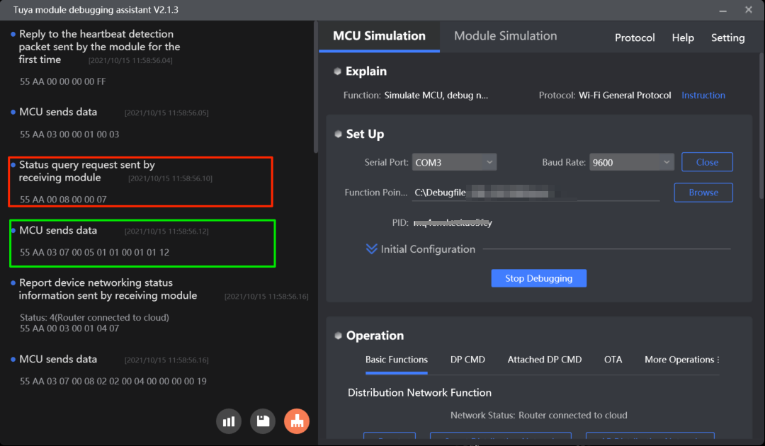
When a device is connected with the mobile app, the app can send control commands to the module. The module sends the received command to the MCU through serial communication. The MCU processes the command.
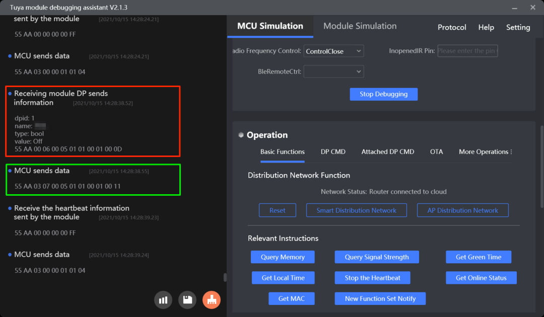
-
It calls
0x07to respond to the received command. For example, the mobile app sends a command to turn off the switch.-
The module sends
55 AA 00 06 00 05 01 01 00 01 00 0D. -
The MCU returns
55 AA 03 07 00 05 01 01 00 01 00 11.The MCU must respond with the data of the same DP.
-
-
The MCU executes the control command. For example, the MCU receives a command to turn off the air purifier.
The data flow shows that the device has been connected to the router and the cloud. Therefore, the network status value is
0x04. The network over which the mobile app sends the command can be a WAN or a LAN. Without internet access, the device communicates with the mobile app over a LAN, the network status is0x03that indicates the Wi-Fi network is set up, and the device is connected to the router.
Report status asynchronously (0x07)
For more information, see Report status. The MCU asynchronously reports DP status, which can be triggered by three mechanisms.
- When the MCU receives the DP status query (
0x08), it sends the status of all DPs to the module through0x07. - After the MCU executes the command received from the module, it reports the changed DP status to the module.
- When the MCU proactively detects status changes of DPs, it reports the changed DP status to the module through
0x07.
Things to note:
-
Data length: indicates the length of DP data, not the length of a complete frame of data. The data length depends on the DP data type and the number of DPs. If needed, values can be padded on the left with zeros to meet the length requirement. For more information, see Data units.
-
Enum data: Its value ranges from 0 to 255. No matter what particular values you specified as enum values, the data reported must start with zero. For example, the DP of
work_typehas enum valuescold, warm, auto, air, dehumidify, mapping to numeric0,1,2,3,4. To report data ofdehumidify, the digit4will be reported. For the DP oflevelin percentage, it has enum values0,20,40,60,80,100, mapping to0,1,2,3,4,5. To report data of60, the digit3will be reported. If you edit the enum values specified for a DP, the numeric mapping must be updated. For example, the enum values ofwork_typebecomecold, warm, air, dehumidifyafterautois deleted. when the device is paired again, the digit3should be used to report data ofdehumidify. -
Bitmap data: supports reporting multiple faults at the same time. Each bit represents an alert.
1indicates a fault occurs and0indicates no fault occurs. The bitmap data can be one, two, or four bytes. Data greater than one byte is transmitted in big-endian format. For example, if the MCU sends55 aa 03 07 00 06 0d 05 00 02 00 09 2C, it indicates that the faults ofbit0andbit3are reported. If you want to configure alert messages, see Configure Push Notification. -
String data: the denotation of the string data must match the specifications of the control panel on the mobile app. The string data must be converted into hexadecimal values to report. For example, if the MCU sends
55 AA 03 07 00 08 6E 03 00 04 74 65 73 74 46,74 65 73 74denotes the charactertest. -
Raw data: usually used to implement complex features. The raw data is completely passed through between the device and the cloud without processing but with Base64 encoding and decoding. The cloud logs provided by the Tuya Developer Platform are Base64-encoded. You need to decode them first to get the actual data.
- When reporting data, the module performs Base64 encoding on the raw data and the mobile app decodes the Base64-encoded data.
- When sending data, the mobile app performs Base64 encoding on the raw data and the module decodes the Base64-encoded data.
-
Grouped status reporting: indicates the module reports status data of multiple DPs to improve the efficiency of data transfer. For example, the MCU sends
55 aa 03 07 00 0d 03 02 00 04 00 00 00 19 04 04 00 01 00 {checksum}, it indicates the current temperature is 25°C and the operation mode is Smart.
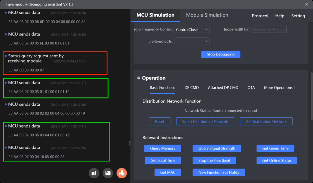
Protocol examples
- Send data: The data marked with a red rectangle indicates the module sends a command to the MCU.
- Report data: The data marked with a green rectangle indicates the MCU reports data to the module, occurring when it reports the changed DP status after executing a command, proactively reports status, or responds to the command
0x08.
MCU SDK sample code
Process received data
data_point_handle() in system.c is used for the MCU to process commands from the module.
The process is as follows:
-
The serial data handler
data_handle()receives the control command sent from the module. -
The MCU calls
data_point_handle()to get the data unit and verify the data format. -
data_point_handle()callsdp_download_handle()to process the received command.dp_download_handle()will call the correct function according to the DP ID to execute the command and return the updated DP status to the module.void data_handle(unsigned short offset) { …… case DATA_QUERT_CMD: // The module sends a control command to the MCU. total_len = (wifi_data_process_buf[offset + LENGTH_HIGH] << 8) | wifi_data_process_buf[offset + LENGTH_LOW]; for(i = 0;i < total_len; ) { dp_len = wifi_data_process_buf[offset + DATA_START + i + 2] * 0x100; dp_len += wifi_data_process_buf[offset + DATA_START + i + 3]; // ret = data_point_handle((unsigned char *)wifi_data_process_buf + offset + DATA_START + i); //The MCU gets the data unit and verifies the data format. if(SUCCESS == ret) { // Success. }else { // Error message. } i += (dp_len + 4); } break; ...... }/** * @brief Process the received commands from the module. * @param[in] {value} The pointer to the received data. * @return Return the processing result. */ static unsigned char data_point_handle(const unsigned char value[]) { unsigned char dp_id,index; unsigned char dp_type; unsigned char ret; unsigned short dp_len; dp_id = value[0]; dp_type = value[1]; dp_len = value[2] * 0x100; dp_len += value[3]; index = get_dowmload_dpid_index(dp_id); if(dp_type != download_cmd[index].dp_type) { // Error message. return FALSE; }else { ret = dp_download_handle(dp_id,value + 4,dp_len); // Calls the correct function according to the DP ID to execute the command and return the updated DP status to the module. } return ret; }
Report status asynchronously
According to data types, the data reporting functions are classified into mcu_dp_raw_update(),mcu_dp_bool_update(), mcu_dp_value_update(), mcu_dp_string_update(), mcu_dp_enum_update(), and mcu_dp_fault_update(), which are defined in mcu_api.c. For example, if a DP is Boolean type, mcu_dp_bool_update() is used for the MCU to report data.
/**
* @brief   Report data of Boolean DPs.
* @param[in] {dpid}  The DP ID.
* @param[in] {value}  The current DP value.
* @return Null
* @note   Null
*/
unsigned char mcu_dp_bool_update(unsigned char dpid,unsigned char value)
{
    unsigned short send_len = 0;

    if(stop_update_flag == ENABLE)
    	   return SUCCESS;
    send_len = set_wifi_uart_byte(send_len,dpid);
    send_len = set_wifi_uart_byte(send_len,DP_TYPE_BOOL);
    //
    send_len = set_wifi_uart_byte(send_len,0);
    send_len = set_wifi_uart_byte(send_len,1);
    //
    if(value == FALSE) {
 	   send_len = set_wifi_uart_byte(send_len,FALSE);
    }else {
 	   send_len = set_wifi_uart_byte(send_len,1);
    }
    wifi_uart_write_frame(STATE_UPLOAD_CMD, MCU_TX_VER, send_len);   // Start reporting.
    return SUCCESS;
}
Next steps
After you implement the basic features, you can proceed with extended features as needed.
Is this page helpful?
YesFeedbackIs this page helpful?
YesFeedback


