Extended Features
This topic describes the extended features that are designed to deliver useful IoT-enabled functionalities, including OTA update, production test, and time sync.
All the protocol examples in this topic are performed on the module debugging assistant. This debugger can help you understand how data transmission works.
Low power solutions
There are three solutions to reduce power consumption.
Idle power-off
For products that cannot be powered by mains power, this solution enables the MCU to power off the Wi-Fi module in idle through control of the power circuit. For more information, see Wi-Fi Low-Power Device Solution.

- The embedded software used for low-power modules is tailored to enable quick boot from the power-off state and connection to the Wi-Fi network.
- The operating current of the low-power Wi-Fi module is lower than the common Wi-Fi module. However, its peak current can be more than 400 mA with a duration of microseconds. The consideration for electricity allowance is required in your circuit design.
Low-power persistent connection
When a paired device is connected to the router but not executing any commands, its power consumption can be lower than 15 mA on average by reducing the consumption of radio frequency.
You can add the low field in the product information to enable the low power mode. When the Wi-Fi and Bluetooth combo module runs in low power mode, it only supports Bluetooth pairing without device control. For example, {"p":"AIp08kLIf****","v":"1.0.0","m":1,"mt":10,"n":0,"ir":"5.12","low":1}
0: disable low power mode.1: enable low power mode.
When a paired device is idle for a certain amount of time (depending on chip specifications), and I/O does not output signals, it will enter low power mode with a consumption of less than 0.2W.
Low-power pairing
When a pairing attempt times out, the module will enter low power mode, the network status 6 with a status value of 0x05. For information about the status details, see the description of the m field in the product information.
OTA firmware updates
An over-the-air (OTA) update is the wireless delivery of new software, firmware, or other data to connected smart devices.
You can upload the update file to the Tuya Developer Platform. The Wi-Fi module can download the file from Tuya’s cloud server and transmit the update file to the MCU through the serial protocol. This way, the MCU gets the file, writes it to the local flash memory, and performs updates. For more information, see Update Firmware and Select and Change the Firmware Version.
Processes
The OTA update consumes the memory of the MCU. After a device is paired, an OTA update can be initiated through preset configuration or check-for updates operation.
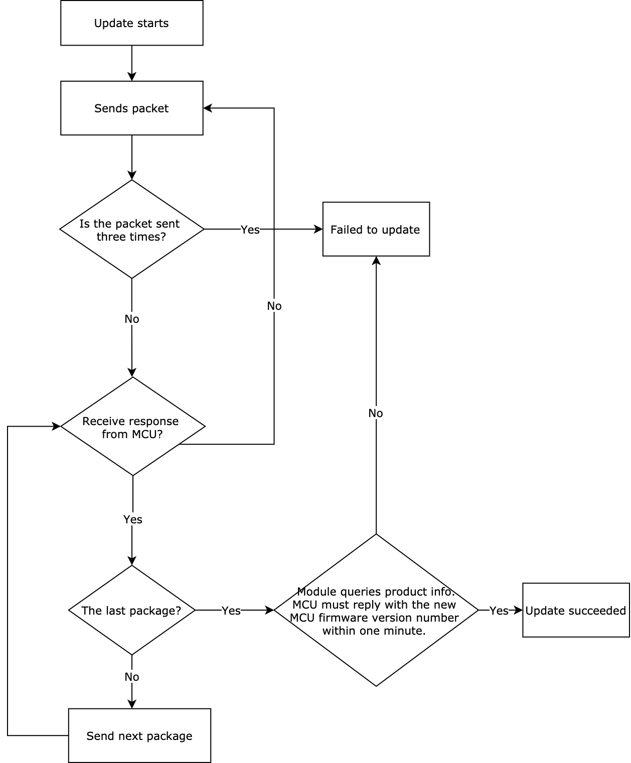
After the module has sent all update packages, it will send the command 0x01 to query the product information. The MCU must reply with the new MCU firmware version number within one minute. The new version number should be consistent with that configured on the Tuya Developer Platform.
Only when all the update packages have been sent to the MCU and the MCU reports the latest firmware version number to the module after a restart, you can declare a successful OTA update.
Scenarios
In debugging phase or after product delivery, you can deploy MCU updates over OTA to fix issues and add new features. The OTA update feature is recommended if your MCU has enough memory resources.
-
Firmware management: You must upload the verified firmware updates to the Tuya Developer Platform for OTA update deployment. For more information, see Update Firmware.
-
Application description: You can implement the Tuya protocol-based serial communication between your MCU and Tuya’s modules through porting MCU SDK or interfacing with the protocol without SDK.
- Porting MCU SDK: With the OTA-related functions provided in the SDK, the MCU can respond with the single packet size, start the update process, and receive and process the update package.
- Interfacing without SDK: You need to implement the OTA-related protocols, and file transfer and processing.
The RAM of your MCU must be greater than 260 bytes. You must implement the basic features of the protocol before working on the OTA feature.
Commands
The commands used in the OTA update.
- Initiate an OTA update:
0x0a - Transmit the update file:
0x0b
Initiate an OTA update (0x0a)
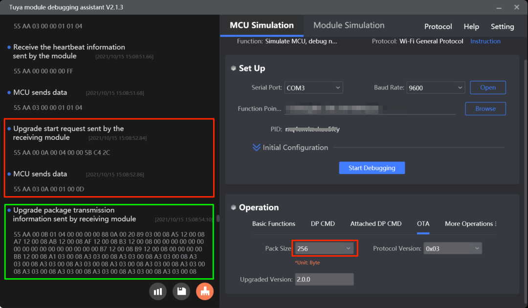
The module will send the command 0x0a to tell the MCU the size of the update file. The MCU returns the transfer size of each package.
The transfer size of each package
| Return value | Size |
|---|---|
| 0x00 | 256 bytes (default and compatible with legacy firmware) |
| 0x01 | 512 bytes |
| 0x02 | 1024 bytes |
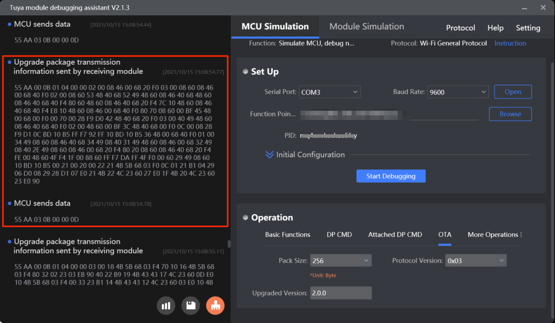
Transmit the update file (0x0b)
The module sends the update file to the MCU in multiple packages. If the MCU does not respond to the updates transfer command within five seconds, the module will resent the command and declare a failed update after three unsuccessful attempts.
For more information, see Update MCU firmware.
Protocol examples
-
Initiate an OTA update
-
Transmit the update file
MCU SDK sample code
For more information about porting SDK, see OTA Update Guide.
Functions used to set the transfer size of each package
upgrade_package_choose() in protocol.c is used for the MCU to set the transfer size of each package.
The process is as follows:
-
Enable
SUPPORT_MCU_FIRM_UPDATEto turn on the OTA update feature. -
The MCU gets the size of the update file from
data_handle()and callsupgrade_package_choose()to return the transfer size of each package.//#define SUPPORT_MCU_FIRM_UPDATE // Enable the OTA update feature, which is disabled by default. /* Firmware package size selection */ #ifdef SUPPORT_MCU_FIRM_UPDATE #define PACKAGE_SIZE 0 // The transfer size of each package is 256 bytes. //#define PACKAGE_SIZE 1 // The transfer size of each package is 512 bytes. //#define PACKAGE_SIZE 2 // The transfer size of each package is 1024 bytes. #endifvoid data_handle(unsigned short offset) { ...... case UPDATE_START_CMD: // Initiate an OTA update with 0x0A. // Get the global variable of the transfer size of each package. firm_flag = PACKAGE_SIZE; if(firm_flag == 0) { firm_size = 256; }else if(firm_flag == 1) { firm_size = 512; }else if(firm_flag == 2) { firm_size = 1024; } firm_length = wifi_data_process_buf[offset + DATA_START]; firm_length <<= 8; firm_length |= wifi_data_process_buf[offset + DATA_START + 1]; firm_length <<= 8; firm_length |= wifi_data_process_buf[offset + DATA_START + 2]; firm_length <<= 8; firm_length |= wifi_data_process_buf[offset + DATA_START + 3];// Get the size of the update file. upgrade_package_choose(PACKAGE_SIZE); // Return the transfer size of each package. firm_update_flag = UPDATE_START_CMD; break; ...... }/** * @brief Set the transfer size of each package. * @param[in] {package_sz} The transfer size of each package. * @ref 0x00: 256 bytes (default) * @ref 0x01: 512 bytes * @ref 0x02: 1024 bytes * @return Null * @note To be implemented by you. */ void upgrade_package_choose(unsigned char package_sz) { #error "Complete the code for setting the transfer size of each package and then delete this row." unsigned short send_len = 0; send_len = set_wifi_uart_byte(send_len, package_sz); wifi_uart_write_frame(UPDATE_START_CMD, MCU_TX_VER, send_len); }
Functions used to transfer the update file
mcu_firm_update_handle() in protocol.c is used to process the received update file.
The process is as follows:
-
The module sends the update package as per the defined transfer size. The MCU receives the package from the
data_handle(). -
The MCU calls
mcu_firm_update_handle()to process the package accordingly.void data_handle(unsigned short offset) { ...... case UPDATE_TRANS_CMD: // Start update file transfer. if(firm_update_flag == UPDATE_START_CMD) { // Stop data reporting. stop_update_flag = ENABLE; total_len = (wifi_data_process_buf[offset + LENGTH_HIGH] << 8) | wifi_data_process_buf[offset + LENGTH_LOW]; dp_len = wifi_data_process_buf[offset + DATA_START]; dp_len <<= 8; dp_len |= wifi_data_process_buf[offset + DATA_START + 1]; dp_len <<= 8; dp_len |= wifi_data_process_buf[offset + DATA_START + 2]; dp_len <<= 8; dp_len |= wifi_data_process_buf[offset + DATA_START + 3]; firmware_addr = (unsigned char *)wifi_data_process_buf; firmware_addr += (offset + DATA_START + 4); if((total_len == 4) && (dp_len == firm_length)) { // The last package. ret = mcu_firm_update_handle(firmware_addr,dp_len,0); firm_update_flag = 0; }else if((total_len - 4) <= firm_size) { ret = mcu_firm_update_handle(firmware_addr,dp_len,total_len - 4); }else { firm_update_flag = 0; ret = ERROR; } if(ret == SUCCESS) { wifi_uart_write_frame(UPDATE_TRANS_CMD, MCU_TX_VER, 0); } // Resume data reporting. stop_update_flag = DISABLE; } break; ...... }/** * @brief The MCU enters the update mode. * @param[in] {value} The buffer. * @param[in] {position} The location where the current package is stored. * @param[in] {length} The length of the current package. When it is zero, the update file transfer is completed. * @return Null * @note To be implemented by you. */ unsigned char mcu_firm_update_handle(const unsigned char value[],unsigned long position,unsigned short length) { #error "Complete the implementation for OTA update and then delete this row." if(length == 0) { // Update file transfer is completed. }else { // Process the received update file. } return SUCCESS; }
Production test
The protocol provides the testing feature. You can verify Wi-Fi or Bluetooth functionalities. For more information, see Production Test. You can also get the Wi-Fi signal strength of the connected network.
Scenarios
After you have tested the basic features, you can perform functionality testing separately or integrate it into the end product test to verify the wireless performance. You can define how a test is triggered as needed.
Commands
The commands used in the functionality test.
- Scan for the designated network:
0x0e - Connect to the designated network:
0x2C - Test Bluetooth functionality:
0x35(subcommand:0x01) - Get the signal strength:
0x24
Scan for the designated network (0x0e)
This command is used to test the radio frequency performance of Wi-Fi modules in mass production.
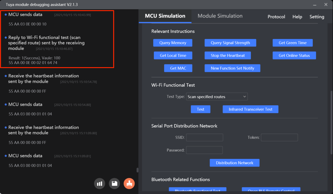
How to use this command: You can call this command at least five seconds after the module is powered on because the initialization takes a while. After the module receives the command 0x0e, it will scan for the Wi-Fi network named tuya_mdev_test and return the result. If the designated network is discovered, the result is the signal strength in percentage, ranging from 0 to 100 with a step of 20. The MCU determines whether the Wi-Fi RF performance is acceptable based on the signal strength.
Signal strength
| Signal strength | Receive power (dBm) |
|---|---|
| 0 | ≤ -100 |
| 40 | > -100, ≤ -80 |
| 60 | > -80, ≤ -60 |
| 80 | > -60, ≤ -40 |
| 100 | > -40 |
- Set up the router: Prepare a 2.4 GHz wireless router and set the router’s SSID to
tuya_mdev_test. Internet connection and password setup are not required. - Testing condition: It is recommended that the distance between the router and the device under test should be about five meters. If the signal strength is greater than or equal to 60%, the device is acceptable. The specific testing conditions depend on your production line and environment. You can test multiple devices at the same time.
Example:
- The MCU sends
55 aa 03 0e 00 00 10. - The module returns
55 aa 00 0e 00 02 01 28 38, indicating the test is successful and the signal strength is 40%.
For more information, see Test Wi-Fi functionality (scanning).
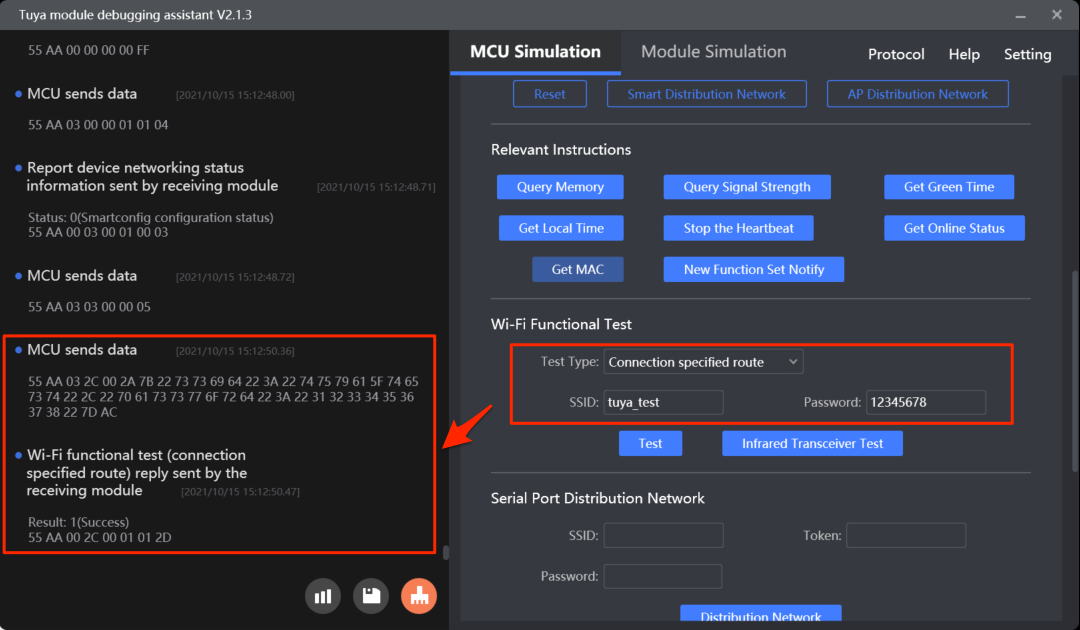
Connect to the designated network (0x2C)
This test requires an internet connection. The network capacity determines you can test limited devices at a time. Note that since the mobile app does not send the pairing token in the test process, the device is not actually connected to the Tuya Developer Platform but the cloud connectivity is verified.
How to use this command: You can call this command at least five seconds after the module is powered on because the initialization takes a while. Make sure that the module has not paired. Otherwise, the test will fail. The MCU sends the SSID and password of the specified router to the module through 0x2c. The module connects to the router and returns the status of cloud connectivity so that the MCU can determine the test result based on what the module returns.
- The network status 4 (
0x03) is the only metric to determine whether the device is connected to the router. - The test is failed if one of the following conditions occurs:
- The MCU receives a failure result.
- The MCU does not receive the packet of network status 4 within 15 seconds.
- After a successful test, you can send the command again to repeat the test. If the MCU does not receive the packet of network status 4, it means the module is in the testing mode. In this situation, you must reset or restart the module to perform a test again.
- The maximum length of the SSID and password is 32 bytes and 64 bytes respectively.
Example:
- The MCU sends
55AA 03 2C 00 23 7B 22 73 73 69 64 22 3A 22 74 65 73 74 22 2C 22 70 61 73 73 77 6F 72 64 22 3A 22 31 32 33 34 35 36 22 7D 14, indicating{"ssid":"test","password":"123456"}. - The module returns
55 AA 00 2C 00 01 01 2D, indicating a successful test.
For more information, see Test Wi-Fi functionality (connection).
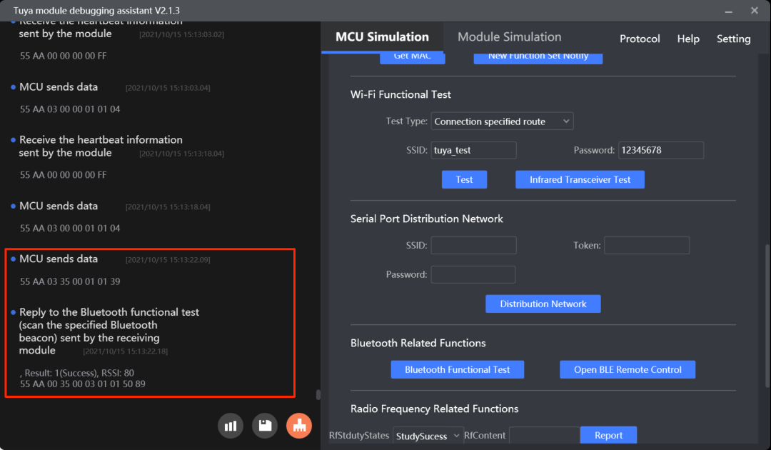
Test Bluetooth functionality (0x35, subcommand 0x01)
The module scans for the designated Bluetooth beacon ty_mdev and returns the result and signal strength in percentage. For more information about the signal strength description, see Scan for the designated network.
Testing condition: Prepare a Bluetooth beacon and set its identifier to ty_mdev. It is recommended that the distance between the router and the device under test should be about five meters. If the signal strength is greater than or equal to 60%, the device is acceptable. The specific testing conditions depend on your production line and environment.
Example:
-
The MCU sends
55 aa 03 35 00 01 01 {checksum}. -
The module sends
55 aa 00 35 00 03 01 01 28 {checksum}, indicating the test is successful and the signal strength is 40%.
For more information, see (Optional) Bluetooth features.
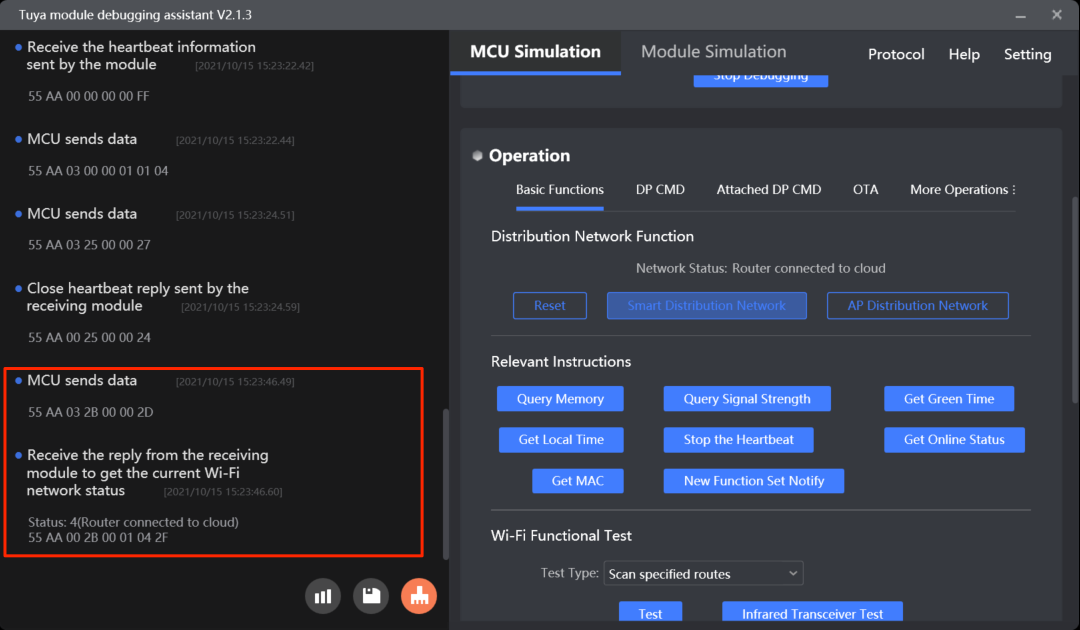
Get the signal strength (0x24)
If the module is connected to the Wi-Fi network, the MCU can send this command to get the current signal strength to determine the network quality.
If a device has been paired with the mobile app, you can view the signal strength on the Device Information page from the app.
Example:
- The MCU sends
55 aa 03 24 00 00 26. - The module returns
55 aa 00 24 00 01 D5 F9, indicating the received signal strength indicator (RSSI) is -43 dB.
For more information, see (Optional) Get Wi-Fi signal strength.
The signal strength value is in hexadecimal format (padding). If the RSSI is less than -70 dB, the possibility that a device gets offline is high. Check the network environment and antenna performance.
Protocol examples
- Scan for the designated network
- Connect to the designated network
- Test Bluetooth functionality
MCU SDK sample code
Scan for the designated network
wifi_test_result() in protocol.c is used for the MCU to get the test result.
The process is as follows:
-
Enable
WIFI_TEST_ENABLEto turn on the Wi-Fi functionality test. -
The MCU gets the test result from
data_handle()and callswifi_test_result()to process the result.#define WIFI_TEST_ENABLE // Enable Wi-Fi functionality test.void data_handle(unsigned short offset) { ...... #ifdef WIFI_TEST_ENABLE case WIFI_TEST_CMD: // Scan for the designated network. result = wifi_data_process_buf[offset + DATA_START]; rssi = wifi_data_process_buf[offset + DATA_START + 1]; wifi_test_result(result, rssi); break; #endif ...... }/** * @brief Get the Wi-Fi functionality test result. * @param[in] {result} The test result. * @ref 0: Failed * @ref 1: Succeeded * @param[in] {rssi} If the test is successful, the signal strength will be returned. Otherwise, error codes will be returned. * @return Null * @note To be implemented by you. */ void wifi_test_result(unsigned char result,unsigned char rssi) { #error "Complete the code for test results and then delete this row." if(result == 0) { // Test failed. if(rssi == 0x00) { // The network with an SSID of `tuya_mdev_test` is not found. }else if(rssi == 0x01) { // The module is not authorized. } }else { // Test succeeded. // RSSI indicates the signal strength, ranging from 0 to 100. 0 represents the weakest, and 100 represents the strongest. } }
Connect to the designated network
mcu_start_connect_wifitest() in mcu_api.c is used for the MCU to send the SSID and password of the designated network to the module to initiate the connection test.
The process is as follows:
-
Enable
WIFI_CONNECT_TEST_ENABLEto turn on the functionality test on the Wi-Fi connection. -
The MCU calls
mcu_start_connect_wifitest()to report the SSID and password of the designated network to initiate a test. -
The MCU gets the test result from
data_handle()and callswifi_connect_test_result()to process the result.//#define WIFI_CONNECT_TEST_ENABLE // Enable functionality test on the Wi-Fi connection.void data_handle(unsigned short offset) { ...... #ifdef WIFI_CONNECT_TEST_ENABLE case WIFI_CONNECT_TEST_CMD: // Connect to the designated Wi-Fi network. result = wifi_data_process_buf[offset + DATA_START]; wifi_connect_test_result(result); break; #endif ...... }/** * @brief The MCU initiates a functionality test on the Wi-Fi connection. * @param[in] {ssid_buf} The location where the SSID string is saved. The length of an SSID can be up to 32 bytes. * @param[in] {passwd_buffer} The location where the password string is saved. The length of a password can be up to 64 bytes. * @return Null * @note To be implemented by you. */ void mcu_start_connect_wifitest(unsigned char *ssid_buf,unsigned char *passwd_buffer) { unsigned short send_len = 0; if( my_strlen(ssid_buf) > 32 || my_strlen(passwd_buffer) > 64) { //printf("ssid_buf or passwd_buffer is too long!"); return; } send_len = set_wifi_uart_buffer(send_len, "{\"ssid\":\"", my_strlen("{\"ssid\":\"")); send_len = set_wifi_uart_buffer(send_len,ssid_buf,my_strlen(ssid_buf)); send_len = set_wifi_uart_buffer(send_len, "\",\"password\":\"", my_strlen("\",\"password\":\"")); send_len = set_wifi_uart_buffer(send_len,passwd_buffer,my_strlen(passwd_buffer)); send_len = set_wifi_uart_buffer(send_len, "\"}", my_strlen("\"}")); wifi_uart_write_frame(WIFI_CONNECT_TEST_CMD, MCU_TX_VER, send_len); }/** * @brief Notification of the result of network information reception. * @param[in] {result} Indicates whether the module gets the designated network information. * @ref 0x00: Failed * @ref 0x01: Succeeded * @return Null * @note To be implemented by you. */ void wifi_connect_test_result(unsigned char result) { #error "Complete the code for test results and then delete this row." if(result == 0) { // The module fails to get the information. Verify the JSON packet integrity. }else { // The module gets the information. `WIFI_STATE_CMD` provides the network status. } }
Bluetooth functionality test
mcu_start_BLE_test() in mcu_api.c is used for the MCU to initiate an Bluetooth functionality test.
The process is as follows:
-
Enable
BLE_RELATED_FUNCTION_ENABLEto turn on Bluetooth functionalities. -
The MCU calls
mcu_start_BLE_test()to enable scanning for the designated Bluetooth identifier. -
The MCU gets the test result from
data_handle()and callsBLE_test_result()to process the result.//#define BLE_RELATED_FUNCTION_ENABLE // Turn on Bluetooth functionalities./** * @brief The MCU initiates a functionality test on scanning for the designated Bluetooth identifier. * @param Null * @return Null * @note To be implemented by you. */ void mcu_start_BLE_test(void) { unsigned short send_len = 0; send_len = set_wifi_uart_byte(send_len, 0x01); wifi_uart_write_frame(BLE_TEST_CMD, MCU_TX_VER, send_len); }void data_handle(unsigned short offset) { ...... #ifdef BLE_RELATED_FUNCTION_ENABLE case BLE_TEST_CMD: // Scan for the designated Bluetooth identifier. total_len = (wifi_data_process_buf[offset + LENGTH_HIGH] << 8) | wifi_data_process_buf[offset + LENGTH_LOW]; BLE_test_result((unsigned char *)(wifi_data_process_buf + offset + DATA_START), total_len); break; #endif ...... }/** * @brief * @brief Get the Bluetooth functionality test. * @param[in] {value} The buffer. * @param[in] {length} The data length. * @return Null * @note To be implemented by you. */ void BLE_test_result(const unsigned char value[], unsigned short length) { #error "Complete the code for test results and then delete this row." unsigned char sub_cmd = value[0]; if(0x03 != length) { // Data length error. return; } if(0x01 != sub_cmd) { // Subcommand error. return; } unsigned char result = value[1]; unsigned char rssi = value[2]; if(result == 0) { // Test failed. if(rssi == 0x00) { // The Bluetooth identifier named `ty_mdev` is not found. }else if(rssi == 0x01) { // The module is not authorized. } }else if(result == 0x01) { // Test succeeded. // RSSI indicates the signal strength, ranging from 0 to 100. 0 represents the weakest, and 100 represents the strongest. } }
Time synchronization
The MCU can get the Greenwich Mean Time (GMT) and local time. After the module is connected to the cloud, the MCU can request the current system time.
The MCU gets the system time of the module. After the module is connected to the cloud, it will automatically sync time with the cloud server on each data interaction or every six hours if no interaction occurs. The module has built-in RTC. If the module is offline, the MCU gets its RTC time.
After the module is powered on and connected to the cloud, it will proactively notify the MCU after it has synced time with the cloud server. The module will not immediately sync time with the cloud server after it is connected to the cloud. However, during this period, the MCU still keeps requesting time data. This notification feature allows the MCU to wait for the message from the module without keeping asking.
The time offset between the built-in RTC time and the server time is less than 10 seconds within 24 hours.
Scenarios
If your device displays the system time, or some features depend on the time data, you can use this command to get the current time.
To get the accurate time data on the first time request, the MCU should send the command five seconds after the module is connected to the cloud. For later requests, the frequency can vary depending on applications but should be more than one second.
Commands
The commands used in time synchronization.
- Get the GMT:
0x0C - Get the local time:
0x1C - Enable time service notification:
0x34(subcommand:0x01) - Notify the MCU of time service:
0x34(subcommand:0x02)
Get the GMT (0x0C)
As the international standard of civil time, GMT is independent of the time zone and DST. The MCU can proactively request the GMT.
After connecting to the network, the module returns success and valid time data after the local timestamp is synced.
Example:
-
The MCU sends
55 aa 03 0c 00 00 0e. -
The module returns
55 aa 00 0c 00 07 01 10 04 13 05 06 07 4c, indicating GMT at 05:06:07 on April 19, 2016.
For more information, see Get system time in GMT.
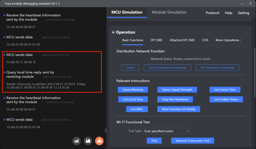
Get the local time (0x1C)
The local time is calculated by adding the time zone offset and DST to the GMT. The time zone is where the device is activated.
The local time indicates the system time zone on the mobile app that is paired with the device.
-
If a device is activated in mainland China, the local time is Beijing time (GMT+08:00).
-
If the device is activated in other countries or regions, the local time is the time zone on the mobile phone.
Example:
-
The MCU sends
55 aa 03 1C 00 00 1E. -
The module returns
55 aa 00 1c 00 08 01 10 04 13 05 06 07 02 5f(Beijing time at 05:06:07 on April 19, 2016)
For more information, see Get local time.
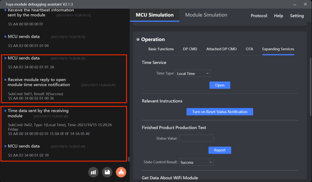
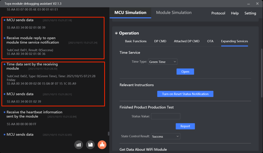
Enable time service notification (0x34, subcommand 0x01)
How to use the command: After power-on, the MCU sends the command to enable the time service notification and selects the time service. The module enables the time service accordingly and returns the result.
If the time service has already been enabled, the module will reject the repeated enablement request unless it is restarted. In this case, the MCU should use the common command of getting time data.
Example:
- The MCU sends
55 AA 03 34 00 02 01 00 39, indicating the GMT service is required. - The module returns
55 AA 00 34 00 02 01 00 36, indicating the required service is enabled.
Notify the MCU of time service (0x34, subcommand 0x02)
How to use the command: After the module synchronizes time with the cloud server, it sends the time data to the MCU.
After the module is restarted, the time service is disabled. The MCU must send the command to enable the time service notification.
Example:
-
The module sends
55 AA 00 34 00 09 02 00 15 06 02 03 05 11 03 77, indicating GMT at 03:05:17 on June 2, 2021, Wednesday. -
The MCU returns
55 AA 03 34 00 01 02 39.
For more information, see Extended services.
Protocol examples
- Get the GMT

- Get the local time
- Enable time service notification
- Send time data
MCU SDK sample code
Get the GMT
mcu_get_green_time() in mcu_api.c is used for the MCU to proactively request the GMT.
The process is as follows:
-
Enable
SUPPORT_GREEN_TIMEto turn on the GMT service. -
The MCU calls
mcu_get_green_time()to request GMT. -
The MCU gets the time data from
data_handle()and callsmcu_get_greentime()to proceed with the next operation.//#define SUPPORT_GREEN_TIME // Turn on the GMT service./** * @brief The MCU gets the GMT. * @param Null * @return Null * @note To be implemented by you. */ void mcu_get_green_time(void) { wifi_uart_write_frame(GET_ONLINE_TIME_CMD, MCU_TX_VER, 0); }void data_handle(unsigned short offset) { ...... #ifdef SUPPORT_GREEN_TIME case GET_ONLINE_TIME_CMD: // Get the GMT. mcu_get_greentime((unsigned char *)(wifi_data_process_buf + offset + DATA_START)); break; #endif ...... }/** * @brief Get the GMT. * @param[in] {time} The GMT. * @return Null * @note To be implemented by you. */ void mcu_get_greentime(unsigned char time[]) { #error "Complete the code and delete this row." /* time[0]: indicates whether the GMT is obtained successfully. `0`: failure. `1`: success. time[1] indicates the year. `0x00` indicates the year 2000. time[2] indicates the month, ranging from 1 to 12. time[3] indicates the day, ranging from 1 to 31. time[4] indicates the hour, ranging from 0 to 23. time[5] indicates the minute, ranging from 0 to 59. time[6] indicates the second, ranging from 0 to 59. */ if(time[0] == 1) { // Correct GMT is received. }else { // Correct GMT is not received. It might because the module is not connected to the network. } }
Get the local time
mcu_get_system_time() in mcu_api.c is used for the MCU to proactively request the local time.
The process is as follows:
-
Enable
SUPPORT_MCU_RTC_CHECKto turn on the local time service. -
The MCU calls
mcu_get_system_time()to request the local time. -
The MCU gets the time data from
data_handle()and callsmcu_write_rtctime()to proceed with the next operation.//#define SUPPORT_MCU_RTC_CHECK // Enable time sync with the cloud server./** * @brief The MCU gets the system time of the module to sync with its local clock. * @param Null * @return Null * @note The MCU calls `mcu_write_rtctime` to sync time with the RTC time. */ void mcu_get_system_time(void) { wifi_uart_write_frame(GET_LOCAL_TIME_CMD, MCU_TX_VER, 0); }void data_handle(unsigned short offset) { ...... #ifdef SUPPORT_MCU_RTC_CHECK case GET_LOCAL_TIME_CMD: // Get the local time. mcu_write_rtctime((unsigned char *)(wifi_data_process_buf + offset + DATA_START)); break; #endif ...... }/** * @brief The MCU syncs time with the local RTC. * @param[in] {time} The GMT. * @return Null * @note To be implemented by you. */ void mcu_write_rtctime(unsigned char time[]) { #error "Complete the code for time sync with RTC and delete this row." /* Time[0] indicates whether the local time is obtained successfully. `0`: failure. `1`: success. Time[1] indicates the year. `0x00` indicates the year 2000. Time[2] indicates the month, ranging from 1 to 12. Time[3] indicates the day, ranging from 1 to 31. Time[4] indicates the hour, ranging from 0 to 23. Time[5] indicates the minute, ranging from 0 to 59. Time[6] indicates the second, ranging from 0 to 59. Time[7] indicates the week, ranging from 1 to 7. `1` indicates Monday. */ if(time[0] == 1) { // The correct local time is received. }else { // Correct local time is not received. It might be because the module is not connected to the network. } }
Enable time service notification
open_module_time_serve() in mcu_api.c is used for the MCU to enable the time service notification.
The process is as follows:
-
Enable
MODULE_EXPANDING_SERVICE_ENABLEto turn on the extension feature. -
The MCU proactively calls
open_module_time_serve()to enable the time service notification and select the time service. -
The MCU gets the enablement result from
data_handle()and callsopen_module_time_serve_result()to proceed with the next operation.//#define MODULE_EXPANDING_SERVICE_ENABLE // Enable the extension feature./** * @brief Enable the time service notification. * @param[in] {time_type} The type of time service. * @ref 0x00: GMT * @ref 0x01: local time * @return Null * @note To be implemented by you. */ void open_module_time_serve(unsigned char time_type) { unsigned short send_len = 0; send_len = set_wifi_uart_byte(send_len, 0x01); send_len = set_wifi_uart_byte(send_len, time_type); wifi_uart_write_frame(MODULE_EXTEND_FUN_CMD, MCU_TX_VER, send_len); }void data_handle(unsigned short offset) { ...... #ifdef MODULE_EXPANDING_SERVICE_ENABLE case MODULE_EXTEND_FUN_CMD: // The extension feature. total_len = (wifi_data_process_buf[offset + LENGTH_HIGH] << 8) | wifi_data_process_buf[offset + LENGTH_LOW]; open_module_time_serve_result((unsigned char *)(wifi_data_process_buf + offset + DATA_START), total_len); break; #endif ...... }/** * @brief The result of enabling the time service notification. * @param[in] {value} The buffer. * @param[in] {length} The data length. * @return Null * @note To be implemented by you. */ void open_module_time_serve_result(const unsigned char value[], unsigned short length) { ...... case 0x01: { // The subcommand to enable the time service notification. if(0x02 != length) { // Data length error. return; } if(value[1] == 0) { // The service is enabled. }else { // Failed to enable the service. } } break; ...... }
Time service notification
The MCU gets the time data and calls open_module_time_serve_result() to proceed with the next operation.
//#define MODULE_EXPANDING_SERVICE_ENABLE // Enable the extension feature.
void data_handle(unsigned short offset)
{
	……
	#ifdef MODULE_EXPANDING_SERVICE_ENABLE
		case MODULE_EXTEND_FUN_CMD:                             // The extension feature.
			total_len = (wifi_data_process_buf[offset + LENGTH_HIGH] << 8) | wifi_data_process_buf[offset + LENGTH_LOW];
			open_module_time_serve_result((unsigned char *)(wifi_data_process_buf + offset + DATA_START), total_len);
		break;
	#endif
	……
	}
/**
* @brief   The result of enabling the time service notification.
* @param[in] {value}  The buffer.
* @param[in] {length}  The data length.
* @return Null
* @note   To be implemented by you.
*/
void open_module_time_serve_result(const unsigned char value[], unsigned short length)
{
	……
	case 0x02: {  //  The subcommand to notify the MCU of the time service.
			if(0x09 != length) {
				  // Data length error.
				return;
			}
			unsigned char time_type = value[1]; // 0x00: the GMT.    0x01: the local time.
			unsigned char time_data[7];
			my_memcpy(time_data, value + 2, length - 2);
			/*
			Data[0] indicates the year. `0x00` indicates the year 2000.
			Data[1] indicates the month, ranging from 1 to 12.
			Data[2] indicates the day, ranging from 1 to 31.
			Data[3] indicates the hour, ranging from 0 to 23.
			Data[4] indicates the minute, ranging from 0 to 59.
			Data[5] indicates the second, ranging from 0 to 59.
			Data[6] indicates the week, ranging from 1 to 7. `1` indicates Monday.
			*/
			  // Implement the time data handler. `time_type` indicates the type of time service, which can be GMT or local time.
			unsigned short send_len = 0;
			send_len = set_wifi_uart_byte(send_len,sub_cmd);
			wifi_uart_write_frame(MODULE_EXTEND_FUN_CMD, MCU_TX_VER, send_len);
		}
		break;
		......
}
Weather data
You can enable the weather service to allow the module to get the current weather and upcoming forecast. For more information, see Weather Service.
Scenarios
After the module is connected to the cloud, the MCU can send the module a command to enable the weather service. This way, the module will send weather data to the MCU on a regular basis.
The weather location depends on the latitude and longitude where a mobile phone is located.
Commands
The commands used in the weather service.
- Enable the weather service:
0x20 - Send weather data:
0x21 - Proactively request weather data:
0x34(subcommand:0x03)
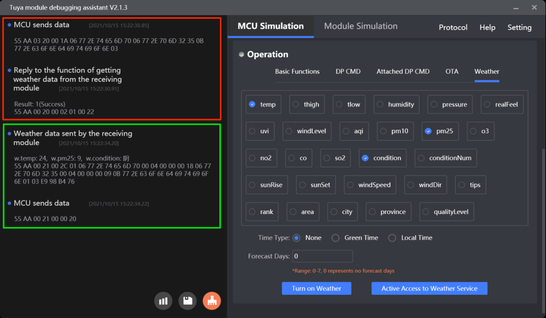
Enable the weather service (0x20)
How to use the command: After initialization, the MCU can call this command to enable the weather service. The module returns the result.
Example:
-
The MCU sends
55 AA 03 20 00 0E 06 77 2E 74 65 6D 70 06 77 2E 70 6D 32 35 80, indicatingL:0x06, K:w.temp, L:0x06, K:w.pm25. -
The module returns
55 AA 00 20 00 02 01 00 22, indicating success.
For more information, see (Optional) Enable weather services.
Send weather data (0x21)
With the weather service enabled, if the module is connected to the cloud, it will send weather data to the MCU regularly. The module will send the weather data immediately as the weather service is enabled and then send data every 30 minutes. The MCU can also send 0x21 to the module to proactively request weather data.
Example: w.temp: 15, w.humidity: 23, w.pm25: 27, w.conditionNum: 120 represents a weather condition of sunny. For more information, see Weather data in UTF-8 encoding.
| Weather service | Hexadecimal | Weather data | Hexadecimal |
|---|---|---|---|
| w.temp | 77 2E 74 65 6D 70 | 15 | 00 00 00 0F |
| w.humidity | 77 2E 68 75 6D 69 64 69 74 79 | 23 | 00 00 00 17 |
| w.pm25 | 77 2E 70 6D 32 35 | 27 | 00 00 00 1B |
| w.conditionNum | 77 2E 63 6F 6E 64 69 74 69 6F 6E 4E 75 6D | 120 | 31 32 30 |
- The module sends
55 AA 00 21 00 40 01 06 77 2E 74 65 6D 70 00 04 00 00 00 0F 0A 77 2E 68 75 6D 69 64 69 74 79 00 04 00 00 00 17 06 77 2E 70 6D 32 35 00 04 00 00 00 1B 0E 77 2E 63 6F 6E 64 69 74 69 6F 6E 4E 75 6D 01 03 31 32 30 5B. - The MCU returns
55 aa 00 21 00 00 20.
For more information, see (Optional) Send weather data.
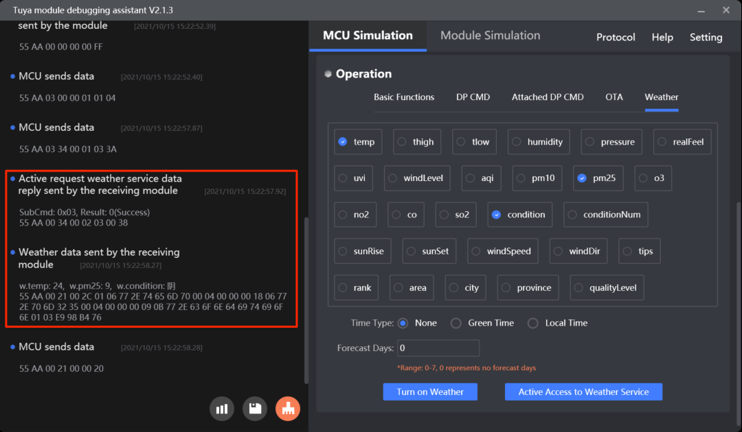
Proactively request weather data (0x34, subcommand 0x03)
Besides passively receiving weather data from the module, the MCU can proactively request weather data using this command.
- The minimum request interval is one minute. If the MCU sends multiple requests within one minute, the request is only processed once.
- The module only uses this command to confirm a request and sends weather data still through the command
0x21.
For more information, see Extended services.
Protocol examples
- Enable the weather service and send weather data
- Proactively request weather data
MCU SDK sample code
Enable the weather service
mcu_open_weather() in protocol.c is used for the MCU to proactively send a command to the module to enable the weather service.
The process is as follows:
-
Enable
WEATHER_ENABLEto turn on the weather feature and configure the weather conditions and forecasts. -
The MCU calls
mcu_open_weather()to enable the weather service. -
The MCU gets the enablement result from
data_handle()and callsweather_open_return_handle()to proceed with the next operation.//#define WEATHER_ENABLE // Enable the weather service. #ifdef WEATHER_ENABLE /* You can set the weather data parameters in the `weather_choose` array in the `protocol.c` and write the number of weather data types to this macro. */ #define WEATHER_CHOOSE_CNT 4 // Specify the number of weather data parameters. /* When you enable the weather service, you can set this macro to specify the number of days for which the API returns forecast data. The valid value ranges from 1 to 7. Setting to `1` returns the weather of the current day, without a forecast. */ #define WEATHER_FORECAST_DAYS_NUM 1 // Specify the number of days for which the API returns forecast data. #endif/** * @brief Enable the weather service. * @param Null * @return Null */ void mcu_open_weather(void) { int i = 0; char buffer[13] = {0}; unsigned char weather_len = 0; unsigned short send_len = 0; weather_len = sizeof(weather_choose) / sizeof(weather_choose[0]); for(i=0;i<weather_len;i++) { buffer[0] = sprintf(buffer+1,"w.%s",weather_choose[i]); send_len = set_wifi_uart_buffer(send_len, (unsigned char *)buffer, buffer[0]+1); } #error "Complete the implementation for enabling the weather service and then delete this row." /* // To get the time-dependent weather data, such as sunrise and sunset, you must use the `t.unix` or `t.local` parameter to request data in GMT or local time. buffer[0] = sprintf(buffer+1,"t.unix"); // The GMT. buffer[0] = sprintf(buffer+1,"t.local"); // The local time. send_len = set_wifi_uart_buffer(send_len, (unsigned char *)buffer, buffer[0]+1); */ buffer[0] = sprintf(buffer+1,"w.date.%d",WEATHER_FORECAST_DAYS_NUM); send_len = set_wifi_uart_buffer(send_len, (unsigned char *)buffer, buffer[0]+1); wifi_uart_write_frame(WEATHER_OPEN_CMD, MCU_TX_VER, send_len); }void data_handle(unsigned short offset) { ...... case WEATHER_OPEN_CMD: // The result of enabling the weather service. weather_open_return_handle(wifi_data_process_buf[offset + DATA_START], wifi_data_process_buf[offset + DATA_START + 1]); break; ...... }/** * @brief The value that the function for enabling weather service returns. * @param[in] {res} The result of enabling the weather service. * @ref 0: Failed * @ref 1: Succeeded * @param[in] {err} The error code. * @return Null * @note To be implemented by you. */ void weather_open_return_handle(unsigned char res, unsigned char err) { #error "Complete the implementation for the return result of enabling the weather service and then delete this row." unsigned char err_num = 0; if(res == 1) { // Return success. }else if(res == 0) { // Return failure. // Get the error code. err_num = err; } }#ifdef WEATHER_ENABLE if(wifi_work_state == WIFI_CONNECTED && isWoSend == 0) { // After the module is connected to the cloud, the MCU sends a command to the module to enable the weather service. mcu_open_weather(); isWoSend = 1; } #endif
Send weather data
weather_data_raw_handle() in system.c is used for the MCU to receive weather data from the module.
The process is as follows:
-
The MCU gets weather data from
data_handle(). -
Then, it calls
weather_data_raw_handle()to parse weather data and proceed with the next operation.weather_data_user_handle()is intended to be implemented by you. The following sample code is for reference only.void data_handle(unsigned short offset) { ...... case WEATHER_DATA_CMD: // The module sends weather data. total_len = (wifi_data_process_buf[offset + LENGTH_HIGH] << 8) | wifi_data_process_buf[offset + LENGTH_LOW]; weather_data_raw_handle((unsigned char *)wifi_data_process_buf + offset + DATA_START, total_len); break; ...... }/** * @brief Parse weather data. * @param[in] {p_data} The pointer to the received data. * @param[in] {data_len} The length of the received data. * @return Null */ static void weather_data_raw_handle(const unsigned char p_data[], unsigned short data_len) { int i = 1; int can_len = 0; char can[15] = {0}; char day = 0; int type1 = 0; unsigned char value_string[100] = {0}; int val_cnt = 0; int val_len = 0; if(p_data[0] != 1 || data_len < 1) { // Failed to receive weather data. }else { if(data_len < 4) { // Weather data is empty. } while (i < data_len) { can_len = p_data[i]; my_memset(can, '\0', 15); my_memcpy(can, p_data + i + 1, can_len - 2); day = p_data[i + can_len] - '0'; type1 = p_data[i + 1 + can_len]; if(type1 != 0 && type1 != 1) { return; } my_memset(value_string, '\0', 100); val_cnt = i + 1 + can_len + 1; val_len = p_data[val_cnt]; if (type1 == 0) { //int32 weather_data_user_handle(can+2, type1, p_data+val_cnt+1, day); } else if(type1 == 1) { //string my_memcpy(value_string, p_data + val_cnt + 1, val_len); weather_data_user_handle(can+2, type1, value_string, day); } i += 1 + can_len + 1 + 1 + val_len; } wifi_uart_write_frame(WEATHER_DATA_CMD, 0, 0); } }/** * @brief The function for processing weather data. * @param[in] {name} The parameter name. * @param[in] {type} The parameter type. * @ref 0: The integer type. * @ref 1: The string type. * @param[in] {data} The address of the parameter value. * @param[in] {day} The number of days for which the API returns forecast data. The value ranges from 0 to 6 and 0 indicates the current day. * @ref 0: today * @ref 1: tomorrow * @return Null * @note To be implemented by you. */ void weather_data_user_handle(char *name, unsigned char type, const unsigned char *data, char day) { #error "Complete the code and delete this row." int value_int; char value_string[50];// Defaults to 50. You can adjust it based on your defined parameters. my_memset(value_string, '\0', 50); // Get the data type. if(type == 0) { // The integer type. value_int = data[0] << 24 | data[1] << 16 | data[2] << 8 | data[3]; }else if(type == 1) { my_strcpy(value_string, data); } // Note that you must request the parameter value according to the selected parameters. if(my_strcmp(name, "temp") == 0) { printf("day:%d temp value is:%d\r\n", day, value_int); // The integer type. }else if(my_strcmp(name, "humidity") == 0) { printf("day:%d humidity value is:%d\r\n", day, value_int); // The integer type. }else if(my_strcmp(name, "pm25") == 0) { printf("day:%d pm25 value is:%d\r\n", day, value_int); // The integer type. }else if(my_strcmp(name, "condition") == 0) { printf("day:%d condition value is:%s\r\n", day, value_string); // The string type. } }
Proactively request weather data
request_weather_serve() in mcu_api.c is used for the MCU to proactively request weather data.
The process is as follows:
-
Enable
MODULE_EXPANDING_SERVICE_ENABLEto turn on the extension feature. -
The MCU calls
request_weather_serve()to proactively request weather data. -
The MCU gets the request result from
data_handle()and callsopen_module_time_serve_result()to proceed with the next operation.//#define MODULE_EXPANDING_SERVICE_ENABLE // Enable the extension feature./** * @brief The MCU proactively requests weather data. * @param Null * @return Null * @note To be implemented by you. */ void request_weather_serve(void) { unsigned short send_len = 0; send_len = set_wifi_uart_byte(send_len, 0x03); wifi_uart_write_frame(MODULE_EXTEND_FUN_CMD, MCU_TX_VER, send_len); }void data_handle(unsigned short offset) { ...... #ifdef MODULE_EXPANDING_SERVICE_ENABLE case MODULE_EXTEND_FUN_CMD: // The extension feature. total_len = (wifi_data_process_buf[offset + LENGTH_HIGH] << 8) | wifi_data_process_buf[offset + LENGTH_LOW]; open_module_time_serve_result((unsigned char *)(wifi_data_process_buf + offset + DATA_START), total_len); break; #endif ...... }/** * @brief The result of enabling the time service notification. * @param[in] {value} The buffer. * @param[in] {length} The data length. * @return Null * @note To be implemented by you. */ void open_module_time_serve_result(const unsigned char value[], unsigned short length) { ...... case 0x03: { // The subcommand to proactively request weather data. if(0x02 != length) { // Data length error. return; } if(value[1] == 0) { // Succeeded }else { // Failed } } break; ...... }
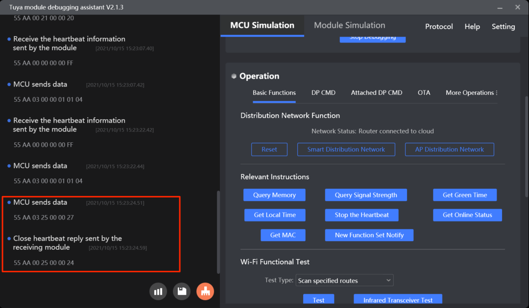
Disable heartbeats
The MCU can send the module a command to disable heartbeat communication.
Scenarios
Before the module goes to sleep for reducing power consumption, the MCU can send this command to notify the module to disable the heartbeat.
Commands
Notify the module to disable heartbeat communication: 0x25
- Because heartbeats are required for building communication between the module and the MCU, this command must not be sent when the device is just powered on.
- This command is not retained after power is removed. Therefore, after power-on, the MCU must disable heartbeats after a heartbeat connection has been established.
For more information, see (Optional) Disable heartbeats.
Protocol examples
MCU SDK sample code
Disable heartbeats
wifi_heart_stop() in mcu_api.c is used for the MCU to send the command to disable heartbeat communication.
The process is as follows:
-
Enable
WIFI_HEARTSTOP_ENABLEto turn on the feature of disabling heartbeat communication. -
The MCU calls
wifi_heart_stop()to disable heartbeat communication when needed./****************************************************************************** 8: Whether to turn on the feature of disabling heartbeat communication. After you enable it, the MCU can call `wifi_heart_stop` in `mcu_api.c` to disable heartbeat communication when needed. ******************************************************************************/ //#define WIFI_HEARTSTOP_ENABLE // Turn on the feature of disabling heartbeat communication./** * @brief Notify the module to disable heartbeat communication. * @param Null * @return Null * @note To be implemented by you. */ void wifi_heart_stop(void) { wifi_uart_write_frame(HEAT_BEAT_STOP, MCU_TX_VER, 0); }
Get network status
The MCU can send this command to the module to proactively request the network status.
Scenarios
The module proactively sends the current network status to the MCU only when it detects a restart or reconnection. The MCU can send this command to the module to proactively request the current network status.
Commands
Get network status: 0x2B
0x03 is used for the module to proactively report its current network status to the MCU when the module’s status changes.
The command to proactively request the network status should be called after the device initialization is completed. It is recommended that MCU sends the 0x2B command after it receives the 0x03 command, or 5 to 10 seconds after the initialization is completed.
For more information, see Get Wi-Fi status.
Protocol examples
MCU SDK sample code
Get Wi-Fi status proactively
mcu_get_wifi_connect_status() in mcu_api.c is used for the MCU to proactively request the current network status.
The process is as follows:
-
Enable
GET_WIFI_STATUS_ENABLEto turn on the feature of proactive request for the current network status. -
The MCU can call
mcu_get_wifi_connect_status()to send the module the command0x2Bto request the current network status. -
The MCU gets the
resultfromdata_handle()and callsget_wifi_status()to proceed with the next operation.//#define GET_WIFI_STATUS_ENABLE // Turn on the feature of proactive request for the current network status.void data_handle(unsigned short offset) { ...... #ifdef GET_WIFI_STATUS_ENABLE case GET_WIFI_STATUS_CMD: // Get the current network status. result = wifi_data_process_buf[offset + DATA_START]; get_wifi_status(result); break; #endif ...... }#ifdef GET_WIFI_STATUS_ENABLE /** * @brief Get the current network status. * @param Null * @return Null * @note To be implemented by you. */ void mcu_get_wifi_connect_status(void) { wifi_uart_write_frame(GET_WIFI_STATUS_CMD, MCU_TX_VER, 0); } #endif
Notify the module reset
A module can be reset with operations on the hardware or the mobile app. However, the MCU will not be notified of related status. This feature will enable the module to proactively send its status to the MCU.
Scenarios
The MCU can get notified of a module reset.
Commands
The commands used in the notification of module reset.
- Enable notification of module reset:
0x34(subcommand:0x04) - Notify the MCU of a reset event:
0x34(subcommand:0x05)
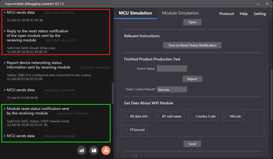
Enable notification of module reset: (0x34, subcommand 0x04)
The MCU sends this command to enable notification of module reset.
Example:
- The MCU sends
55 aa 03 34 00 01 04 3B. - The module returns
55 aa 00 34 00 02 04 00 39, indicating notification is enabled.
For more information, see Extended services.
This command is not retained after power is removed. Therefore, after power-on, the MCU must send this command again to enable this feature.
Notify the MCU of a reset event: (0x34, subcommand 0x05)
The module sends this command to notify the MCU of a reset event.
Example:
-
The module sends
55 aa 00 34 00 02 05 02 3C, indicating it is reset to factory defaults. -
The MCU returns
55 aa 03 34 00 01 05 3C.
For more information, see Extended services.
The module will resend the packet two times at a one second interval if it receives no response.
Protocol examples
MCU SDK sample code
Notify status of module reset
open_module_reset_state_serve() in mcu_api.c is used for the MCU to enable notification of module reset.
The process is as follows:
-
Enable
MODULE_EXPANDING_SERVICE_ENABLEto turn on the extension feature. -
The MCU proactively calls
open_module_reset_state_serve()to enable notification of module reset. -
The MCU gets the enablement result from
data_handle()and callsopen_module_time_serve_result()to proceed with the next operation.//#define MODULE_EXPANDING_SERVICE_ENABLE // Enable the extension feature./** * @brief Enable notification of module reset. * @param Null * @return Null * @note To be implemented by you. */ void open_module_reset_state_serve(void) { unsigned short send_len = 0; send_len = set_wifi_uart_byte(send_len, 0x04); wifi_uart_write_frame(MODULE_EXTEND_FUN_CMD, MCU_TX_VER, send_len); }void data_handle(unsigned short offset) { ...... #ifdef MODULE_EXPANDING_SERVICE_ENABLE case MODULE_EXTEND_FUN_CMD: // The extension feature. total_len = (wifi_data_process_buf[offset + LENGTH_HIGH] << 8) | wifi_data_process_buf[offset + LENGTH_LOW]; open_module_time_serve_result((unsigned char *)(wifi_data_process_buf + offset + DATA_START), total_len); break; #endif ...... }/** * @brief The result of enabling the time service notification. * @param[in] {value} The buffer. * @param[in] {length} The data length. * @return Null * @note To be implemented by you. */ void open_module_time_serve_result(const unsigned char value[], unsigned short length) { ...... case 0x04: { // The subcommand to enable notification of module reset. if(0x02 != length) { // Data length error. return; } if(value[1] == 0) { // Succeeded }else { // Failed } } break; }
Notify status of module reset
The MCU gets the notification and calls open_module_time_serve_result() to proceed with the next operation.
//#define MODULE_EXPANDING_SERVICE_ENABLE // Enable the extension feature.
void data_handle(unsigned short offset)
{
	……
	#ifdef MODULE_EXPANDING_SERVICE_ENABLE
		case MODULE_EXTEND_FUN_CMD:                             // The extension feature.
			total_len = (wifi_data_process_buf[offset + LENGTH_HIGH] << 8) | wifi_data_process_buf[offset + LENGTH_LOW];
			open_module_time_serve_result((unsigned char *)(wifi_data_process_buf + offset + DATA_START), total_len);
		break;
	#endif
		......
	}
/**
* @brief   The result of enabling the time service notification.
* @param[in] {value}  The buffer.
* @param[in] {length}  The data length.
* @return Null
* @note   To be implemented by you.
*/
void open_module_time_serve_result(const unsigned char value[], unsigned short length)
{
	……
	case 0x05: {  // The subcommand to notify a reset event.
			if(0x02 != length) {
				  // Data length error.
				return;
			}
			switch(value[1]) {
				case 0x00:
					    // Reset by hardware operation.
				break;
				case 0x01:
					    // Reset performed on the mobile app.
				break;
				case 0x02:
					    // Factory reset performed on the mobile app.
				break;
				default:break;
			}
			unsigned short send_len = 0;
			send_len = set_wifi_uart_byte(send_len, sub_cmd);
			wifi_uart_write_frame(MODULE_EXTEND_FUN_CMD, MCU_TX_VER, send_len);
		}
		break;
		......
}
Report status synchronously
0x07 is used for status reporting in an asynchronous manner while 0x22 is used for reporting in a synchronous manner. Synchronous reporting enables the MCU to be notified of the result of each status reporting.
Scenarios
Synchronous reporting consumes more resources than those used for asynchronous reporting so synchronous reporting is recommended for the following situations.
- Verify the reporting result by the response from the module.
- The status reported in a synchronous manner will not be filtered out by the module.
Commands
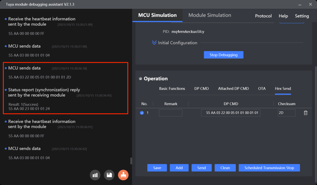
Report status synchronously: 0x22
The MCU can send this command to report status synchronously. The data format is the same as the one used for the asynchronous reporting command 0x07. The MCU cannot report status again until receiving a result from the module. The sequential identical data of the same DP will not be filtered out.
For more information, see Report status (synchronous).
If the data fails to be reported due to poor network quality, the module will return a failure code five seconds after receiving the command.
Protocol examples
MCU SDK sample code
Report status synchronously
According to data types, the synchronous status reporting functions are classified into: mcu_dp_raw_update_syn(), mcu_dp_bool_update_syn(), mcu_dp_value_update_syn(), mcu_dp_string_update_syn(), mcu_dp_enum_update_syn(), and mcu_dp_fault_update_syn(), which are defined inmcu_api.c.
The process is as follows:
-
Enable
MCU_DP_UPLOAD_SYNto turn on synchronous status reporting. -
The MCU calls the synchronous status reporting function to report DP status.
-
The MCU gets the reporting result from
data_handle()and callsget_upload_syn_result()to proceed with the next operation. If the module returns a failure, the MCU can report the status again.//#define MCU_DP_UPLOAD_SYN // Turn on synchronous status reporting.void data_handle(unsigned short offset) { ...... #ifdef MCU_DP_UPLOAD_SYN case STATE_UPLOAD_SYN_RECV_CMD: // Report status synchronously. result = wifi_data_process_buf[offset + DATA_START]; get_upload_syn_result(result); break; #endif ...... }/** * @brief Report DP data of raw type synchronously. * @param[in] {dpid} The DP ID. * @param[in] {value} The pointer to the current DP value. * @param[in] {len} The data length. * @return Null * @note Null */ unsigned char mcu_dp_raw_update_syn(unsigned char dpid,const unsigned char value[],unsigned short len) { unsigned short send_len = 0; if(stop_update_flag == ENABLE) return SUCCESS; // send_len = set_wifi_uart_byte(send_len,dpid); send_len = set_wifi_uart_byte(send_len,DP_TYPE_RAW); // send_len = set_wifi_uart_byte(send_len,len / 0x100); send_len = set_wifi_uart_byte(send_len,len % 0x100); // send_len = set_wifi_uart_buffer(send_len,(unsigned char *)value,len); wifi_uart_write_frame(STATE_UPLOAD_SYN_CMD,MCU_TX_VER,send_len); return SUCCESS; }void get_upload_syn_result(unsigned char result) { #error "Complete the implementation of the return result and delete this row." if(result == 0) { // An error occurred. }else { // Status is reported successfully. } }
Infrared (IR) feature
This additional capability can empower your product with the feature of the smart IR remote control hub.
- For more information about the feature introduction, see IR Capability Integration.
- For more information about hardware design, see IR Hardware Reference.
- For more information about the production test, see IR Production Test.
Map streaming
This feature is used for robot vacuums to stream maps of cleaning tasks. For more information, see (Optional) Map streaming for robot vacuum.
Radio frequency (RF)
For more information, see (Optional) RF functionality.
File download
For more information, see (Optional) File download.
Bluetooth remote controls
For more information, see (Optional) Bluetooth features.
Smart fan
For more information about features specific to smart fans, see (Optional) Smart fan features.
Is this page helpful?
YesFeedbackIs this page helpful?
YesFeedback


