Port HomeKit MCU SDK
The HomeKit MCU SDK contains all you need to get started with MCU development, such as functions and sample code. It is automatically generated based on the product features defined on the Tuya Developer Platform. This topic describes how to port the HomeKit MCU SDK to your project.
Overview
The HomeKit MCU SDK is automatically generated based on the product features defined on the Tuya Developer Platform. With the built-in support for communication and protocol parsing, the HomeKit MCU SDK can facilitate interfacing with Tuya’s Wi-Fi module. You can add this SDK to existing projects and complete the required configuration to implement the MCU program development.
Requirements
SDK requirements for the MCU are as follows. If your MCU does not have sufficient resources, you can refer to the functions in the SDK for interfacing with Tuya’s protocol.
- Memory: 4 KB
- RAM: About 100 bytes of the RAM are required, depending on the data length of the data point (DP). If you enable OTA updates, it must be greater than 260 bytes.
- Nested function: 9-level.
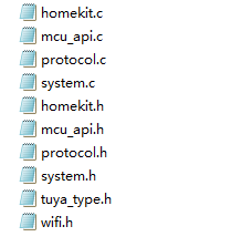
File structure
| Files | Description |
|---|---|
mcu_api.c |
Contains functions that can be called. |
mcu_api.h |
Contains declarations for functions in mcu_api.c. |
protocol.c |
Contains functions for processing protocol data. You can add code to related functions as needed and get data sent by the Wi-Fi module to the MCU. |
protocol.h |
protocol.h contains the following information:
|
system.c |
Contains the implementation of parsing the serial protocol. |
system.h |
system.h contains the following information:
|
wifi.h |
Contains macro definitions for Wi-Fi communication. |
homekit.c |
Contains HomeKit configurations and data handles. |
homekit.h |
homekit.h contains the following information:
|
tuya_type.h |
Definition of the data type, which defaults to 32 bits. If this definition does not apply to your MCU, you can change the data type in this header file. |
How to port SDK
- Program the MCU and port the SDK.
- Check macro definitions in the
protocol.h. - Port the
protocol.cfile and call functions. - Configure HomeKit services and characteristics in
homekit.c. - Add the function call for DP data communication.
- Add the function of device pairing and LED indicator.
- Add the production test feature.
Program MCU and port SDK
-
In your original project, initialize the MCU peripherals, including serial port, external interrupt (button), timer (indicator flickering), and more.
-
Copy the
.cand.hfiles in the MCU SDK folder to your project directory where your other.cand.hfiles are located.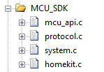
Check macro definitions in protocol.h
Confirm product information
-
Define the product ID (PID).
PRODUCT_KEYis the macro defined for the PID. PID is the unique identifier of each product and can be found on the Smart Products page on the Tuya Developer Platform.#define PRODUCT_KEY "ax23rawjo4np****"If the
PRODUCT_KEYand the PID are inconsistent, you can go to Hardware Development > Download Documents section and download the latest SDK. -
Define the version number.
MCU_VERdefines the software version, which defaults to1.0.0. If you enable OTA updates for the MCU firmware, you need to add the new MCU version number after updates.#define MCU_VER "1.0.0" -
Select HomeKit accessory category. The category name must follow the accessory categories defined by HomeKit Accessory Protocol (HAP). For example, if you create an air purifier on the HomeKit platform, you must choose air purifier as the product type.
/* Select HomeKit accessory category. Configure services and characteristics in `homekit.c` */ //#define HOMEKIT_PRODUCT_TYPE 3 // Fan //#define HOMEKIT_PRODUCT_TYPE 4 // Garage Door Opener //#define HOMEKIT_PRODUCT_TYPE 5 // Lighting //#define HOMEKIT_PRODUCT_TYPE 9 // Thermostat //#define HOMEKIT_PRODUCT_TYPE 12 // Door //#define HOMEKIT_PRODUCT_TYPE 13 // Window //#define HOMEKIT_PRODUCT_TYPE 14 // Window Covering #define HOMEKIT_PRODUCT_TYPE 19 // Air Purifier //#define HOMEKIT_PRODUCT_TYPE 20 // Heater //#define HOMEKIT_PRODUCT_TYPE 22 // Humidifier //#define HOMEKIT_PRODUCT_TYPE 23 // Dehumidifier //#define HOMEKIT_PRODUCT_TYPE 28 // Sprinkler //#define HOMEKIT_PRODUCT_TYPE 29 // Faucet //#define HOMEKIT_PRODUCT_TYPE 30 // Shower System -
Specify whether to configure the valid values of characteristics.
/* Specify whether to configure the valid values of characteristics. */
//#define HOMEKIT_CHARACTER_VALID_CFG_ENABLE
Configure the valid values of characteristics in
char_valid_value_cfg./** * @brief Configure the valid values of characteristics. * @param Null * @return Null * @note */ static void char_valid_value_cfg(void) { //#error "Complete the code and delete this row." static u8 cfg_count = 0; u16 send_len = 0; char strbuff[80] = {0}; u8 strlen = 0; switch(cfg_count++) { case 0: // Configure valid values. // For example, strlen = sprintf(strbuff, "{\"service_serial\":7,\"char_str\":\"A9\",\"val_type\":0,\"valid_val\":[0,2]}"); break; // If you have multiple characteristics to be configured, add case. // case 1: // // Configure valid values. // break; default: // Configuration is completed. send_len = set_wifi_uart_byte(send_len, HK_SUB_CMD_CFG_QUERY); wifi_uart_write_frame(HOMEKIT_FUN_CMD, MCU_TX_VER, send_len); cfg_count = 0; return; break; } send_len = set_wifi_uart_byte(send_len, HK_SUB_CMD_CHARACTER_VALID_CFG); send_len = set_wifi_uart_buffer(send_len, strbuff, strlen); wifi_uart_write_frame(HOMEKIT_FUN_CMD, MCU_TX_VER, send_len); }
Set OTA updates (optional)
-
Enable OTA updates. To support OTA firmware updates, define
SUPPORT_MCU_FIRM_UPDATE. OTA updates are disabled by default.#define SUPPORT_MCU_FIRM_UPDATE -
Define the size of a single package.
#ifdef SUPPORT_MCU_FIRM_UPDATE
#define PACKAGE_SIZE                     0        // One update package is 256 bytes.
//#define PACKAGE_SIZE                   1        // One update package is 512 bytes.
//#define PACKAGE_SIZE                   2        // One update package is 1024 bytes.
#endif
For more information about the OTA updates, see Update Firmware.
-
Configure MCU firmware partition
/*  Types of firmware partition */
#define MCU_FIRMWARE_BACKUP_AREA_TYPE   0       // The MCU has two firmware partitions. 0 is the default value.
//#define MCU_FIRMWARE_BACKUP_AREA_TYPE   1       // The MCU has one firmware partition.
The OTA update process differs depending on the types of firmware partition. For more information, see OTA Updates.
- OTA updates read and write flash memory. The system needs to read data and verify whether the correct data is written to flash memory.
- Specify a timeout period for OTA updates so that the MCU will not always be in the data reception status in case of OTA failure.
- Each OTA packet has offset information, which can be used to detect duplicate packets or packet loss.
Transmit and receive buffer (optional)
-
Serial receive buffer: The buffer size depends on how often the serial data handler is called. If the MCU can quickly process serial data, the buffer size can be reduced.
-
Serial transmit buffer: The buffer size must be greater than the maximum length of DP data.
-
Buffer for serial data processing: The buffer size must be greater than the maximum length of DP data. If OTA updates and specific weather services are enabled, the buffer size must be greater than the maximum amount of data.
/******************************************************************************
                          3: Define the transmit and receive buffer:
                     If your MCU has insufficient RAM, you can change the buffer size to 24 bytes.
******************************************************************************/
#ifndef SUPPORT_MCU_FIRM_UPDATE
#define WIFI_UART_RECV_BUF_LMT          16              // The serial receive buffer size, which can be reduced if your MCU has insufficient RAM.
#define WIFI_DATA_PROCESS_LMT           24              // The buffer size for serial data processing. It depends on the amount of DP data. A size greater than 24 bytes is recommended.
#else
#define WIFI_UART_RECV_BUF_LMT          128             // The serial receive buffer size, which can be reduced if your MCU has insufficient RAM.

// Set the proper buffer size. Consider the defined update package and specific weather services, if applicable.
#define WIFI_DATA_PROCESS_LMT           300             // The buffer size for serial data processing. When OTA updates are enabled, if you set the size of a single update package to 256 bytes, the buffer size must be greater than 260 bytes. If weather services are also enabled, more buffer is required.
//#define WIFI_DATA_PROCESS_LMT           600             // The buffer size for serial data processing. When OTA updates are enabled, if you set the size of a single update package to 512 bytes, the buffer size must be greater than 520 bytes. If weather services are also enabled, more buffer is required.
//#define WIFI_DATA_PROCESS_LMT           1200            // The buffer size for serial data processing. When OTA updates are enabled, if you set the size of a single update package to 1024 bytes, the buffer size must be greater than 1030 bytes. If weather services are also enabled, more buffer is required.
#endif
#define WIFIR_UART_SEND_BUF_LMT         60              // It depends on the amount of DP data but must be greater than 51 bytes.
Define how the module works (required)
-
If the reset button and LED indicator for network status are connected to the MCU, the module works with the MCU to process network events, which is most commonly used. You need to comment out the macro
WIFI_CONTROL_SELF_MODE.//#define WIFI_CONTROL_SELF_MODE // If you use the module self-processing mode, enable this macro and specify I/Os for Tuya-defined Wi-Fi status indicator, HomeKit-defined Wi-Fi status indicator, and the reset button. If your MCU works with the module to process network events, you need to disable this macro. -
If the reset button and LED indicator for network status are connected to the Wi-Fi module, the module processes network events itself. You need to enable the macro
WIFI_CONTROL_SELF_MODE. Specify the GPIO pins connected to the indicator and the button in the following two macros.#ifdef WIFI_CONTROL_SELF_MODE // The module processes network events itself. #define TY_STATE_LED 0 // Tuya-defined Wi-Fi status indicator. Set it according to your circuit. #define HK_STATE_LED 4 // HomeKit-defined Wi-Fi status indicator. Set it according to your circuit. #define WF_RESERT_KEY 5 // Wi-Fi module reset button. Set it according to your circuit. #endif
Enable production test feature (optional)
The production test feature for the Wi-Fi module is enabled by default. To help you smoothly and efficiently carry out mass production, it is recommended to enable the production test feature.
#define WIFI_TEST_ENABLE // Enable the production test feature.
For more information, see Production Test Guide.
Other features (optional)
You can complete corresponding functions to implement specific features.
Port protocol.c file and call functions
-
Copy the
wifi.hfile to the folder where Wi-Fi files are stored, such as themain.cfolder. -
Call
wifi_protocol_init()function in themcu_api.cfile after the MCU serial port and other peripherals are initialized. -
Specify the function of single-byte data transmission in
uart_transmit_outputin theprotocol.cfile, and delete#error./** * @brief Send serial data * @param[in] {value} The 1-byte data to be transmitted. * @return Null */ void uart_transmit_output(u8 value) { //#error "Specify the UART transmission function and delete this line." UART3_SendByte(value); } -
In the interrupt handler function for serial data reception, call
uart_receive_inputin themcu_api.cfile. Use the returned value as the parameter.void UART3_SendByte(unsigned char data) { while((USART3->SR&UART_FLAG_TXE)!=UART_FLAG_TXE); USART3->DR = data; } -
After the MCU executes the
while(1)loop, it calls thewifi_uart_service()function in themcu_api.cfile. The sample code inmain.cis as follows:#include "wifi.h" ... void main(void) { wifi_protocol_init(); ... while(1) { wifi_uart_service(); ... } ... }The MCU must directly call
wifi_uart_service() function in themcu_api.cfile duringwhile(1)loop. After the program is initialized, if an interrupt service routine (ISR) is necessary, you must keep it as short as possible and not call the data reporting function to avoid loss of data.
Call DP data communication function
The DP supports six data types.
- Boolean
Used for DPs of switch products, such as the switch, ECO, and screen. - Enum
Used for DPs that have multiple kinds of status, such as working mode, fan speed, and swing direction. - Value
Used for DPs that have integer values, such as temperature and battery level. - Fault
Used for reporting device faults, denoted in bitmap format. - String
Used for DPs that transmit data in string format. You can choose the string type if other data types are not applicable. - Raw
Used for DPs that have no requirements for data format, transmitting raw data either in plaintext or encrypted text. The data format, packet, and data parsing must be unified in the sender and the receiver.
To sync DP data with the Home app, you can call homekit_character_upload.
Report data of all DPs
After the module is restarted or paired again, it will initiate a status query. The MCU must return the status of all DPs.
-
Open
protocol.cand find the functionall_data_update(void). -
Specify the initial values in corresponding functions for all DPs to be reported. These values will be displayed on the control panel in the app.
Do not call
all_data_update()because this function will be called at the specified time./** * @brief Upload the status of all DPs to sync with the app. * @param Null * @return Null * @note The MCU implements the data reporting in this function, which must support two data transfer types, namely send only as well as send and report. */ void all_data_update(void) { //#error "Complete the example of two data transfer types and delete this line." // This code is automatically generated. You need to edit it based on the actual DPs. mcu_dp_bool_update(DPID_SWITCH,current on/off status); // Report Boolean data mcu_dp_enum_update(DPID_MODE,current mode); // Report enum data mcu_dp_fault_update(DPID_FAULT,current fault alert); // Report fault data mcu_dp_value_update(DPID_PM25,current PM2.5); // Report value data mcu_dp_value_update(DPID_PM10,current PM10); // Report value data mcu_dp_enum_update(DPID_TIMER,current scheduled tasks); // Report enum data mcu_dp_value_update(DPID_FILTER_PERCENT,current filter life level); // Report value data mcu_dp_value_update(DPID_FILTER_USEH,current filter usage time); // Report value data mcu_dp_bool_update(DPID_PHYSICAL_LOCKED,current child lock status); // Report Boolean data #ifdef HOMEKIT_PRODUCT_TYPE homekit_character_upload_all(); #endif }
Report a single DP
When the status of a single DP changes, the MCU must actively report the current DP status to sync with the app. The data format is mcu_dp_xxxx_updata(DPID_X,n), where DPID_X is the DP whose status changes. You can call each function in all_data_update() individually.
mcu_dp_bool_update(DPID_SWITCH,1); // Report Boolean data
mcu_dp_value_update(DPID_PM25,15); // Report value data
mcu_dp_enum_update(DPID_MODE,2); // Report enum data
mcu_dp_fault_update(DPID_FAULT,0x01); // Report fault data
mcu_dp_string_update(DPID_DAY,"1234",4); // Report string data
Send DP commands
In protocol.c, each DP that can send control commands has an individual command handler. The format is dp_download_xxx_handle(), where xxx is the DP that can send commands. After the function parses the DP, the MCU will execute commands accordingly.
Take the received switch DP data as an example:
/*****************************************************************************
Function name: dp_download_switch_handle
Feature description: the handler of `DPID_SWITCH`.
Input parameters: value indicates the data source
        : length: the length of the data
Return parameters: Return SUCCESS on success and ERROR on failure
Note: For the type of send and report, the module must return the result to the cloud to sync with the app.
*****************************************************************************/
static u8 dp_download_switch_handle(const u8 value[], u16 length)
{
    // For example, a DP of Boolean type
    u8 ret;
    // 0: off. 1: on.
    u8 switch_1;

    switch_1 = mcu_get_dp_download_bool(value,length);
    if(switch_1 == 0) {
        // The switch is off.
    }else {
        // The switch is on.
    }

    // Return the result of the operation.
    ret = mcu_dp_bool_update(DPID_SWITCH,switch_1);
    if(ret == SUCCESS)
        return SUCCESS;
    else
        return ERROR;
}
If the change of device status is not triggered by control commands, the MCU will call mcu_dp_bool_update(DPID_SWITCH_1,switch_1); to upload the current status of the DP for feedback. You can also choose the reporting time as needed.
Add the function of device pairing and LED indicator
The function of pairing and LED indicator is required only when the module works with the MCU to process network events.
To implement device pairing, add the pairing command and LED indicator function. If the module works with the MCU to process network events, you can customize the ways to pair devices and indicate pairing status. Generally, you can set the keypress trigger and LED indication.
Command of device pairing
mcu_reset_wifi() is called in the button handler after the reset button is pressed.
mcu_reset_wifi() will reset the Wi-Fi module. All the pairing information will be cleared.
Pairing guide
To get Wi-Fi module’s network status, call get_wifi_tuya_state() and get_wifi_homekit_state() during while(1) loop. Write the flickering mode of the LED indicator according to the network status.
Tuya-defined network status
| Network status | Description | Status value |
|---|---|---|
| Status 1 | Waiting for connection | The LED flickers at an interval of 250 milliseconds. |
| Status 2 | The Wi-Fi network has been set up but not connected to the router. | The LED indicator is steady off. |
| Status 3 | The Wi-Fi module has been connected to the router but not to the cloud. | The LED indicator is steady off. |
| Status 4 | The Wi-Fi module has been connected to the cloud. | The LED indicator is steady on. |
HomeKit-defined network status
| Network status | Description | Status value |
|---|---|---|
| Status 1 | To be bound or being bound | The LED flickers at an interval of 250 milliseconds. |
| Status 2 | Not connected | The LED indicator is steady off. |
| Status 3 | Connected | The LED indicator is steady on. |
Call get_wifi_tuya_state() and get_wifi_homekit_state() to get Wi-Fi connection status.
void main(void){
    ...
    while(1)
    {
        ...
        switch(get_wifi_tuya_state()) {
            case CONFIG_STATE:  //0x00
                if(Timer3_Value % 2 == 0)   // LED flickers quickly.
                {
                    HAL_GPIO_WritePin(LED1_GPIO_Port,LED1_Pin,GPIO_PIN_SET);
                }
                else
                {
                    HAL_GPIO_WritePin(LED1_GPIO_Port,LED1_Pin,GPIO_PIN_RESET);
                }
            break;
            case WIFI_NOT_CONNECTED:  //0x02
                HAL_GPIO_WritePin(LED1_GPIO_Port,LED1_Pin,GPIO_PIN_SET); // LED is off.
            break;
            case WIFI_CONNECTED:  //0x03
                HAL_GPIO_WritePin(LED1_GPIO_Port,LED1_Pin,GPIO_PIN_SET);// LED is steady on.
            break;
            case WIFI_CONN_CLOUD:  //0x04
                HAL_GPIO_WritePin(LED1_GPIO_Port,LED1_Pin,GPIO_PIN_RESET); // LED is steady on.
            break;
            default:
                HAL_GPIO_WritePin(LED1_GPIO_Port,LED1_Pin,GPIO_PIN_SET);
            break;
        }

        switch(get_wifi_homekit_state()) {
            case CONFIG_STATE:  //0x00
                if(Timer3_Value % 2 == 0)   // LED flickers quickly.
                {
                    HAL_GPIO_WritePin(LED2_GPIO_Port,LED2_Pin,GPIO_PIN_SET);
                }
                else
                {
                    HAL_GPIO_WritePin(LED2_GPIO_Port,LED2_Pin,GPIO_PIN_RESET);
                }
            break;
            case WIFI_NOT_CONNECTED:  //0x02
                HAL_GPIO_WritePin(LED2_GPIO_Port,LED2_Pin,GPIO_PIN_SET); // LED is off.
            break;
            case WIFI_CONNECTED:  //0x03
                HAL_GPIO_WritePin(LED2_GPIO_Port,LED2_Pin,GPIO_PIN_RESET);// LED is steady on.
            break;

            default:
                HAL_GPIO_WritePin(LED2_GPIO_Port,LED2_Pin,GPIO_PIN_SET);
            break;
        }
    }
}
Add production test feature
Scan the specified router For more information, see Production Test.
Port homekit.c and configure HomeKit services and characteristics
-
Configure HomeKit services
Enable the macro for your required HomeKit services. Take the fan as an example.
/****************************************************************************** 1. Select the HomeKit service Enable the required service according to your product features. ******************************************************************************/ #ifdef HOMEKIT_PRODUCT_TYPE #define HOMEKIT_SERV_FAN_V2 // Fan //#define HOMEKIT_SERV_GARAGE_DOOR_OPENER // Garage Door Opener //#define HOMEKIT_SERV_LIGHTBULB // Light Bulb //#define HOMEKIT_SERV_THERMOSTAT // Thermostat //#define HOMEKIT_SERV_DOOR // Door //#define HOMEKIT_SERV_WINDOW // Window //#define HOMEKIT_SERV_WINDOW_COVERING // Window Covering //#define HOMEKIT_SERV_AIR_PURIFIER // Air Purifier //#define HOMEKIT_SERV_FILTER_MAINTENANCE // Filter Maintenance //#define HOMEKIT_SERV_AIR_QUALITY_SENSOR // Air Quality Sensor //#define HOMEKIT_SERV_SLAT // Slat //#define HOMEKIT_SERV_HEATER_COOLER // Heater Cooler //#define HOMEKIT_SERV_HUMIDIFIER_DEHUMIDIFIER // Humidifier Dehumidifier //#define HOMEKIT_SERV_IRRIGATION_SYSTEM // Irrigation System //#define HOMEKIT_SERV_VALVE // Valve //#define HOMEKIT_SERV_FAUCET // Faucet #endif -
Configure optional characteristics
Select optional characteristics for your HomeKit services. Take the fan as an example. The optional characteristics can be current fan state, target fan state, rotation direction, and rotation speed.
/* FAN_V2 Optional characteristics of the fan service */ #ifdef HOMEKIT_SERV_FAN_V2// #define FAN_V2_CHAR_NAME // Name #define FAN_V2_CHAR_CURRENT_FAN_STATE // Current fan state #define FAN_V2_CHAR_TARGET_FAN_STATE // Target fan state #define FAN_V2_CHAR_ROTATION_DIRECTION // Rotation direction #define FAN_V2_CHAR_ROTATION_SPEED // Rotation speed //#define FAN_V2_CHAR_SWING_MODE // Swing mode //#define FAN_V2_CHAR_LOCK_PHYSICAL_CONTROLS // Lock physical controls #endif -
Configure the initial values of characteristics
Set the initial value for each optional characteristic. The minimum value is used as the initial value by default. You can change it as needed.
HOMEKIT_CHARACTER_S fan_v2_character[] = { {fan_v2_char_uuid_active_str, TRUE, TRUE, HAP_DATA_TYPE_UINT, .hap_val.u = 0 /* Assign the initial value */ }, #ifdef FAN_V2_CHAR_NAME {fan_v2_char_uuid_name_str, FALSE, FALSE, HAP_DATA_TYPE_STRING, .hap_val.s = /* Assign the initial value */ }, #endif #ifdef FAN_V2_CHAR_CURRENT_FAN_STATE {fan_v2_char_uuid_current_fan_state_str, FALSE, FALSE, HAP_DATA_TYPE_UINT, .hap_val.u = 0 /* Assign the initial value */ }, #endif #ifdef FAN_V2_CHAR_TARGET_FAN_STATE {fan_v2_char_uuid_target_fan_state_str, FALSE, FALSE, HAP_DATA_TYPE_UINT, .hap_val.u = 0 /* Assign the initial value */ }, #endif #ifdef FAN_V2_CHAR_ROTATION_DIRECTION {fan_v2_char_uuid_rotation_direction_str, FALSE, FALSE, HAP_DATA_TYPE_INT, .hap_val.i = 0 /* Assign the initial value */ }, #endif #ifdef FAN_V2_CHAR_ROTATION_SPEED {fan_v2_char_uuid_rotation_speed_str, FALSE, FALSE, HAP_DATA_TYPE_FLOAT, .hap_val.f = 0 /* Assign the initial value */ }, #endif #ifdef FAN_V2_CHAR_SWING_MODE {fan_v2_char_uuid_swing_mode_str, FALSE, FALSE, HAP_DATA_TYPE_UINT, .hap_val.u = 0 /* Assign the initial value */ }, #endif #ifdef FAN_V2_CHAR_LOCK_PHYSICAL_CONTROLS {fan_v2_char_uuid_lock_physical_controls_str, FALSE, FALSE, HAP_DATA_TYPE_UINT, .hap_val.u = 0 /* Assign the initial value */ }, #endif }; -
Configure service serial number
A configured service is identified by its serial number. This way, you can distinguish between services if you configure multiple identical services for a single product such as an irrigation system. To configure multiple identical services, add them following the code format below.
#ifdef HOMEKIT_SERV_FAN_V2 { 0, // Change the service serial number, which must be unique. hap_serv_uuid_fan_v2_str, FALSE, CNTSOF(fan_v2_character), fan_v2_character, }, #endif -
Process HomeKit characteristic commands
When the MCU receives commands from the module, it should execute the operation accordingly and return the result to the module. Implement the code in
homekit_character_ctrl. To sync HomeKit characteristic data with the Tuya app, call functions such asmcu_dp_bool_update,mcu_dp_value_update, andmcu_dp_enum_updatebased on data types./** * @brief Receive and process HomeKit characteristic commands * @param[in] {serv_serial} Service serial number * @param[in] {p_char_str} Characteristic string identifier * @param[in] {char_data_type} Data type of characteristic * @param[in] {char_val_len} Data length of characteristic * @param[in] {p_char_val} Data of characteristic * @return SUCCESS/ERROR * @note */ u8 homekit_character_ctrl(u8 serv_serial, i8 p_char_str[], u8 char_data_type, u16 char_val_len, HAP_VALUE_T *p_char_val) { //#error "Complete code for processing HomeKit commands and delete this line." u8 serv_i = 0, char_j = 0; for(serv_i = 0; serv_i < CNTSOF(homekit_service); serv_i++) { if(serv_serial == homekit_service[serv_i].serial) { for(char_j = 0; char_j < homekit_service[serv_i].character_amount; char_j++) { if(0 == my_strcmp(p_char_str, homekit_service[serv_i].p_character_arr[char_j].p_character_str)) { if(char_data_type == homekit_service[serv_i].p_character_arr[char_j].hap_val_type) { // Implement code for processing HomeKit characteristic commands. //homekit_service[serv_i].p_service_str: services //homekit_service[serv_i].p_character_arr[char_j].p_character_str: characteristics //char_data_type: data type //char_val_len: data length //p_char_val: data if(0 == my_strcmp(homekit_service[serv_i].p_service_str, HAP_SERV_UUID_AIR_PURIFIER) && 0 == my_strcmp(homekit_service[serv_i].p_character_arr[char_j].p_character_str, HAP_CHAR_UUID_ACTIVE)) { homekit_character_upload(serv_serial, HAP_CHAR_UUID_CURRENT_AIR_PURIFIER_STATE, char_data_type, char_val_len, p_char_val); } // Implement code for returning results to the cloud. For example, homekit_character_upload(serv_serial, homekit_service[serv_i].p_character_arr[char_j].p_character_str, char_data_type, char_val_len, p_char_val); return SUCCESS; } } } return ERROR; } } return ERROR; }
Communication between MCU and Wi-Fi module
Data communication must start after the initialization is completed.
Frame format
For more information about the frame format, see Frame format description.
Initialization communication
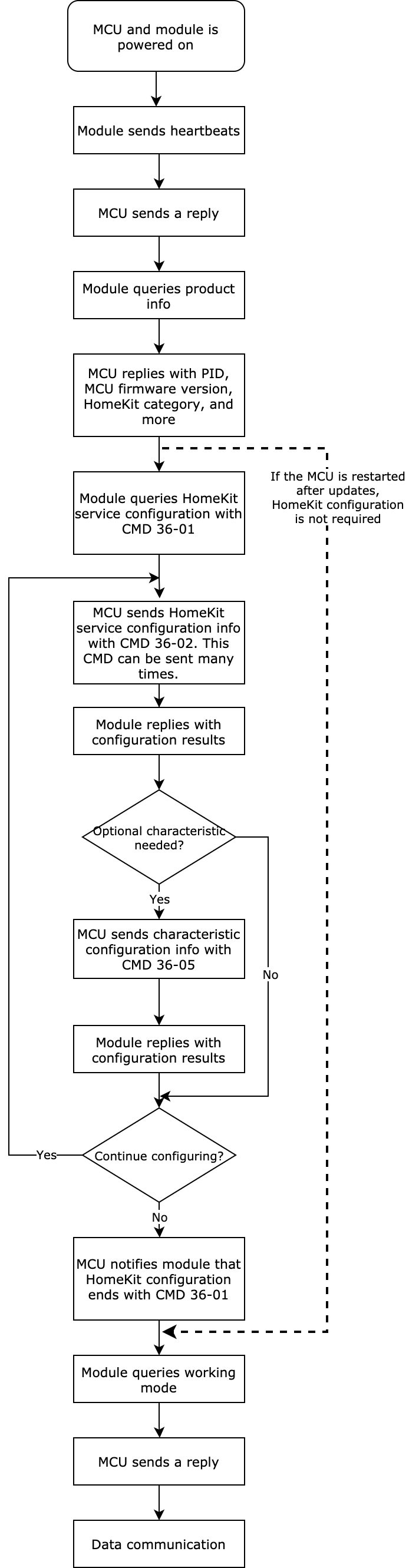
After the MCU and the module are powered on, the initialization configuration starts. Initialization communication includes but is not limited to:
- Verify whether the MCU and the module work properly.
- Verify whether the connection works properly.
- Get the data required for module activation.
- Get the working mode of the module.
Heartbeat
A heartbeat is a type of communication packet between the module and the MCU to check whether the communication was lost. We recommend that the frame of the first communication between the MCU and the module is used as the heartbeat. The communication can work properly only when the heartbeat is sent and responded successfully.
Query product information
After the module builds communication with the MCU, it will query the MCU firmware version and the following information.
- PID: product ID, used to activate the product.
- Version number: MCU firmware version number, used to verify whether the OTA updates are successful.
- Pairing mode: the pairing mode of the module.
Set working mode of the module
The module works with the MCU to process the network event or processes it itself. The working mode is determined by the hardware connection of the LED indicator and reset button on the Wi-Fi module.
The following block diagram shows the initialization communication.
Relation between DP data reporting and network status
In the following two network states, the device can report DP data to and receive DP commands from the app.
- In status 5, the device is connected to the router and the cloud. DP data reporting can work properly.
- In status 4, the device is connected to the router but not to the cloud. The mobile phone can be connected to the router, and DPs can be controlled over the LAN. The DP data can be reported to the app.
OTA updates
This section describes the OTA data communication between the MCU and the Wi-Fi module.
-
OTA starts
When the Wi-Fi module detects an MCU update, it will send a command to start updates.- If the module does not receive a response from the MCU within five seconds, it will resend the package three times. If the MCU still does not respond, the OTA updates fail.
- If the total update package size exceeds the processing capacity of the MCU, the MCU does not respond, and the module will exit OTA updates. In this case, you should check whether the updates uploaded on the Tuya Developer Platform are correct.
-
OTA data transmission starts
After sending a package, if the Wi-Fi module does not receive a response from the MCU within five seconds, it will resend the package three times. If the MCU still does not respond, the OTA updates fail.- If the MCU detects incorrect OTA data, it does not respond. In this case, check the data offset to avoid duplicate packets or packet loss.
- If the MCU processes OTA data too slowly, the module will frequently resend data. Check the data offset to avoid duplicate packets or packet loss. In this case, you can reduce the update package size.
-
OTA transmission is completed
You can determine whether the OTA transmission is completed in the following two ways.
- The frame length is
0x0004, indicating the packet is zero bytes. - The data offset is equal to the total update package size contained in the frame that the Wi-Fi module sends to the MCU for initiating OTA updates.
We recommend using both ways to verify OTA transmission.
- The frame length is
HomeKit certification test
HomeKit certified accessories must meet all the requirements of functionality, which is defined in the HAP specification alongside succeeding in all the Apple-defined test cases. This section describes test cases about communication between the Wi-Fi module and the MCU. For more information about the certification test, visit Apple Developer.
-
TCF039: Test HomeKit setup QR code
Apple issues a unique setup code for each HomeKit-enabled accessory. This code is used to add an accessory to the Home app. Therefore, the value of the category name must follow the rules specified on the HAP. Otherwise, the test will fail. For example, if you create a fan on the HomeKit platform, you must define the HomeKit product type as fan. The following figure shows the sample configuration in the
protocol.h.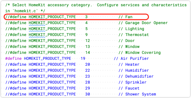
-
TCI014: Test HomeKit characteristic data transmission
With the test tool, you can query, send, and report characteristic data. The available operations depend on the characteristic permission. Query and reporting apply to read-only characteristics. Query, sending, and reporting apply to read-write characteristics.
To test read-only characteristics, the test tool will read the current status. Then, you will be prompted to let the device report a different value to test if the communication works properly. If the value is changed, the test passed. Otherwise, the communication failed. For example, if the current value is
0, you must let the device report a value other than0.To test read-write characteristics, the test tool will read the current status, send a different value, and read the current status again. For example, the set duration (D3) is a read-write characteristic, and its initial value is
0. The test tool sends1to the device, and the device returns1. The cache of this characteristic is1. Then, test data reading the same way as described above. If the device reports1, it indicates the value is not changed, and communication fails.It is recommended to report status to both the Tuya app and Home app.
-
TCH096: Test the accessory prompt
After the test tool sends the command of accessory prompt, the accessory should emit a prompt within 5s, such as flickers or beeps.
If the Wi-Fi module works in the self-processing mode, the HomeKit-defined LED indicator flickers three times to indicate a HomeKit accessory is recognized. If the Wi-Fi module works with the MCU to process network events, after the Wi-Fi module sends HomeKit-defined Wi-Fi status 3, the MCU should emit a prompt within 5s. What signals are emitted depends on your needs. To ensure this accessory prompt will not affect the normal network status indication, the module will send a HomeKit-defined Wi-Fi status 2 around 5s. For more information, see Report network status.
-
TCS003: Stress test on characteristics Run a stress test on a specific characteristic. If you do not use the TYWE3SE module, you need to add the optional characteristic Name. Otherwise, you cannot find available characteristics for testing.
-
TCH091: Verify values Test if the input value is valid. For example, if the valid values of a characteristic are
1,3, and4, you can input2for testing. If writing the value2failed, the test passed. If you do not use one of the default valid values, you must configure valid values of a characteristic. -
TCV004: If you use the valve service, you must specify a name for each valve to use this test case. Pay attention to the following description. Since the Name characteristic is not supported for valves, to have the name of a valve displayed normally, you must configure the Service Label Index characteristic with valid values ranging from 1 to 255. If you have multiple valve services configured, each service is identified by a unique index specified by the Service Label Index characteristic.
For example, you add Service Label Index characteristic to three valve services respectively and assign the value
1,2, and3to the first, second, and third service. These three valves are displayed on the Home app as valve 1, valve 2, and valve 3.
Is this page helpful?
YesFeedbackIs this page helpful?
YesFeedback


