T2-U Development Board
T2-U development board consists of Tuya’s highly-integrated Wi-Fi and Bluetooth module T2-U and peripherals including buttons, LED indicator, GPIOs, power, and USB-to-serial chip.
T2-U development boards are shipped with licenses for cloud connectivity. Do not perform a full chip erase.
Overview
T2-U module comes with a 32-bit RISC MCU that operates at up to 120 MHz and has 2 MB on-chip flash and 256 KB on-chip RAM, with support for TuyaOS custom development. It can connect to the cloud over Wi-Fi and Bluetooth. With the T2-U module, you can develop various smart devices on the Tuya Developer Platform.
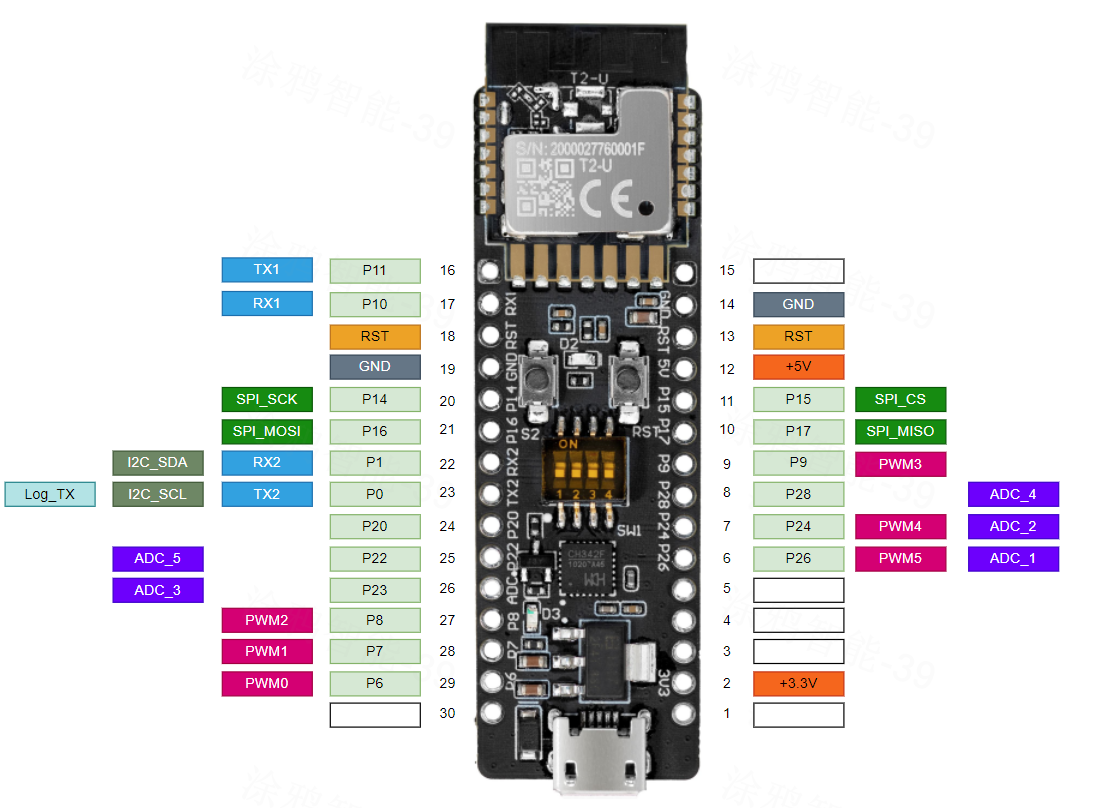
Peripherals
- 6 PWM interfaces
- 4 timers
- 2 UART interfaces
- 1 SPI interface
- 1 I2C interface
- 5 ADC interfaces
- 18 GPIOs
Communication
Wi-Fi
- Support 802.11b, 802.11g, and 802.11n wireless standard.
- Channels 1 to 14 at 2.4 GHz.
- Support security protocols including WEP, WPA/WPA2, WPA/WPA2 PSK (AES), and WPA3.
- A maximum output power of +16 dBm in 802.11b.
- Support three Wi-Fi modes: station mode, AP mode, and dual mode.
- The PCB antenna peak gain is 2.2 dBi.
Bluetooth Low Energy (LE)
- Fully compliant with Bluetooth LE 5.1 standard.
- Priority-based Wi-Fi and Bluetooth coexisting control module for real-time priority and dispatch.
- The transmit power in Bluetooth mode is 6 dBm.
- The PCB antenna peak gain is 2.2 dBi.
Purchasing
- Sample Store on the Tuya Developer Platform.
Development methods
T2-U development board defaults to TuyaOS development. It also supports development using Tuya Connect Kit, Arduino, and MicroPython.
Method 1: TuyaOS development
See the following documentation in order.
Method 2: TuyaOS — T2-U sample
-
Download TuyaOS sample
-
Option 1: Download TuyaOS — T2-U development kit from Tuya Wind IDE for free.
-
Option 2: Download tuyaos-development-board-t2 project from GitHub.
-
-
The sample includes:
-
Sample minimal system to implement cloud connectivity.
-
Development kit for RGB strip lights.
-
Development kit for universal infrared remote control.
-
Examples of using peripherals including ADC, GPIO, I2C, PWM, SPI, timer, and watchdog.
-
Sample code for Wi-Fi features, including station mode, AP mode, scan, and low power.
-
Sample code for Bluetooth LE central and peripheral modes.
-
Sample code for Bluetooth LE and Wi-Fi remote controls (Tuya FFC).
-
RTOS-related thread, mutex, semaphore, message queue, and software timer.
-
Sample code for HTTP file download.
-
Drivers and sample code for energy metering chips including BL0937, BL0942, HLW8032, and HLW8012.
-
Drivers and sample code for RGB light chips including WS2812, WS2814, YX19036, SM16703p, SM16704pk, and SK6812.
-
Drivers and sample code for light chips including PWM, CCT, SM2135E, SM2135EX, SM2x35EGH, KP1805X BP1658CJ, and BP5758D.
More samples will be added over time. You can check Tuya Wind IDE and T2-U development framework on GitHub for updates.
-
Default firmware
T2-U development board is pre-flashed with a demo minimal system for cloud connectivity (apps/tuyaos_demo_quickstart). You can connect the board to the cloud using the SmartLife app. You can also flash the edited demo minimal system or your custom firmware to the board for debugging.
- T2-U development boards are shipped with licenses for cloud connectivity. Do not perform a full chip erase. Otherwise, the board cannot connect to the cloud.
- Default baud rate of the serial port log: 115200.
[01-01 00:00:00 TUYA D][lr:0x9a60b] init fs. Path: null
[01-01 00:00:00 TUYA D][lr:0xb0f89] ***************** kvs_init.
[01-01 00:00:00 TUYA D][lr:0xbcd95] protected init. addr:0x001ed000
[01-01 00:00:00 TUYA D][lr:0xbcc07] init protected data length 435
[01-01 00:00:00 TUYA N][lr:0xb340f] key_addr: 0x1ee000   block_sz 4096
[01-01 00:00:00 TUYA N][lr:0xb34dd] get key:
0x14 0xf1 0x18 0x8e 0x35 0xec 0xef 0x1c 0x1f 0x92 0x27 0x30 0x74 0x2f 0xb 0x92
[01-01 00:00:00 TUYA D][lr:0xbcdb1] protected verify begin
[01-01 00:00:00 TUYA D][lr:0xbcde7] check [gw_bi][244]
[01-01 00:00:00 TUYA D][lr:0xbcde7] check [gw_wsm][119]
[01-01 00:00:00 TUYA D][lr:0xbce23] protected verify end
[01-01 00:00:00 TUYA D][lr:0xb2609] begin try update kv version
[01-01 00:00:00 TUYA D][lr:0xb261f] pre kv version is 2
[01-01 00:00:00 TUYA D][lr:0xb3cd7] 111 k=1  i=2 2
[01-01 00:00:00 TUYA N][lr:0x75809] uni_random_init...
[01-01 00:00:00 TUYA N][lr:0x6ff61] tuya_tls_rand_init ok!
[01-01 00:00:00 TUYA I][lr:0xa2871] mqc app init ...
[01-01 00:00:00 TUYA D][tal_thread.c:203] Thread:sys_timer Exec Start. Set to Running Stat
[01-01 00:00:00 TUYA I][tal_thread.c:184] thread_create name:sys_timer,stackDepth:4096,totalstackDepth:10240,priority:5
[01-01 00:00:00 TUYA I][tal_thread.c:184] thread_create name:wq_system,stackDepth:5120,totalstackDepth:15360,priority:3
[01-01 00:00:00 TUYA I][tal_thread.c:184] thread_create name:wq_highpri,stackDepth:4096,totalstackDepth:19456,priority:4
[01-01 00:00:00 TUYA D][lr:0xa278f] mq_pro:5 cnt:1
[01-01 00:00:00 TUYA D][lr:0xa278f] mq_pro:31 cnt:2
[01-01 00:00:00 TUYA D][tal_thread.c:203] Thread:wq_highpri Exec Start. Set to Running Stat
[01-01 00:00:00 TUYA D][lr:0x9edaf] svc online log init success
[01-01 00:00:00 TUYA E][lr:0xa1fcb] logseq empty
[01-01 00:00:00 TUYA D][tuya_app_main.c:396] device_init in
[01-01 00:00:00 TUYA E][tuya_app_main.c:355] mf_init APP_BIN_NAME[tuyaos_demo_quickstart] USER_SW_VER[1.0.0]
[01-01 00:00:00 TUYA D][lr:0x71c71] mf_core_init success
[01-01 00:00:00 TUYA I][tal_thread.c:184] thread_create name:mf_test,stackDepth:5120,totalstackDepth:24576,priority:4
[01-01 00:00:00 TUYA D][tal_thread.c:200] enter Thread:mf_test func call
[01-01 00:00:00 TUYA D][tal_thread.c:203] Thread:mf_test Exec Start. Set to Running Stat
[01-01 00:00:00 TUYA D][tal_thread.c:203] Thread:wq_system Exec Start. Set to Running Stat
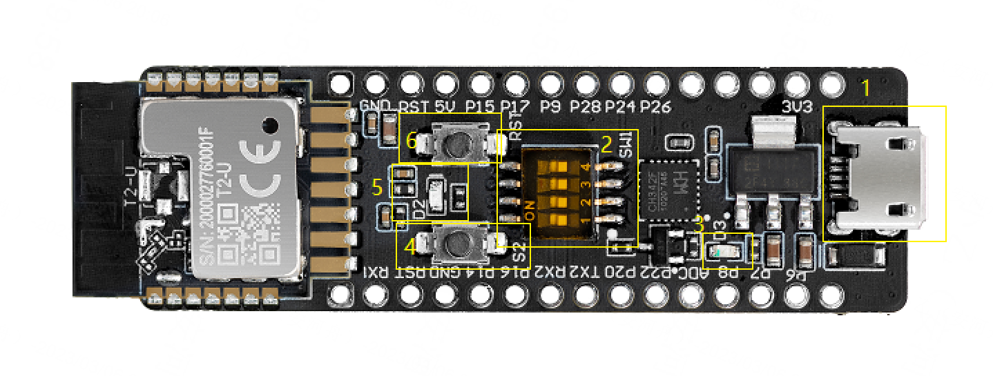
Hardware resource
| Set | No. | Description |
|---|---|---|
| Button | S2 | When the button is pressed, P7 outputs low. When the button is released, it outputs high. |
| Button | RST | When the button is pressed, the module is reset. |
| Indicator | D2 | When P26 outputs low, the LED is on. |
| Indicator | D3 | When the 3.3V power is on, the LED is on. |
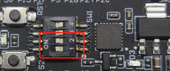
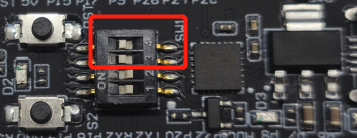
| DIP switch | S1 | Flip the toggle to the ON position to complete the circuit. The switch is used to open and close the circuit between the USB-to-serial chip and the chip’s serial port. |
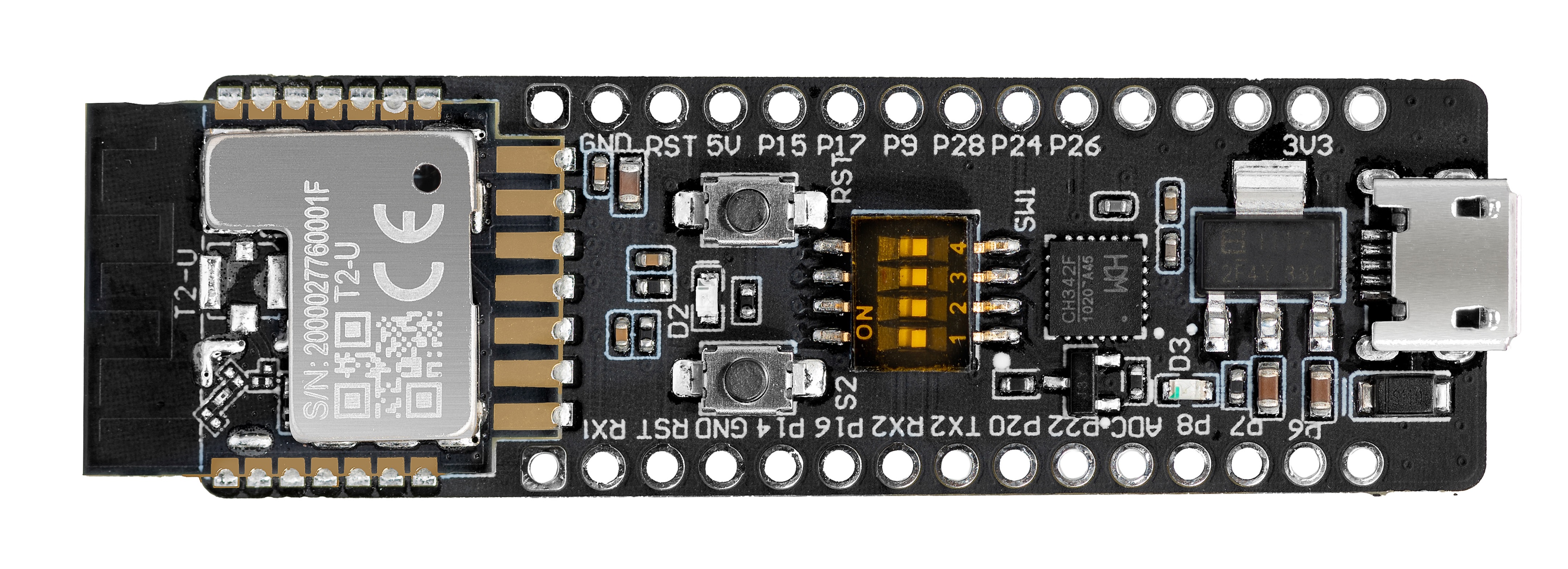
USB to serial
The board comes with a CH343 USB to 2-channel serial chip, which can be used to download code and print logs or act as a normal UART interface.
You can flip the DIP switch (SW1) to enable the 2-channel serial port on the T2-U to connect to the USB-to-serial chip. The following table lists the pin definition of the DIP switch.
| DIP switch No. | 1 | 2 | 3 | 4 |
|---|---|---|---|---|
| Pin on the chip | UART1_RX | UART1_TX | UART2_RX | UART2_TX |
| Pin on USB-to-serial chip | USB-TX0 | USB-RX0 | USB-TX1 | USB-RX1 |
- Flip the toggle to the ON position to complete the circuit. The switch is used to open and close the circuit between the USB-to-serial chip and the chip’s serial port.
- When you use the UART pin on the chip for communication with an MCU or GPIO, flip the toggle of the corresponding channel to the OFF position (the side with numbers) to open the circuit between the UART on T2-U and the USB-to-serial chip.
- The COM port number varies depending on the computers.
Power supply
When micro-USB (CN1) inputs 5V DC voltage, the board can supply power to external components.
-
Power pin:
Power pin Rated voltage/current 5V Depends on the input current of the adapter connected to the DC-005 terminal. 3.3V 3.3V/0.6A -
Output voltage:
Output current 0A 0.15A 0.3A 0.45A 0.6A 0.75A Output voltage 3.34V 3.36V 3.37V 3.37V 3.38V 3.38V We tested the voltage under the condition that there is no output voltage on the micro-USB (CN1) terminal.
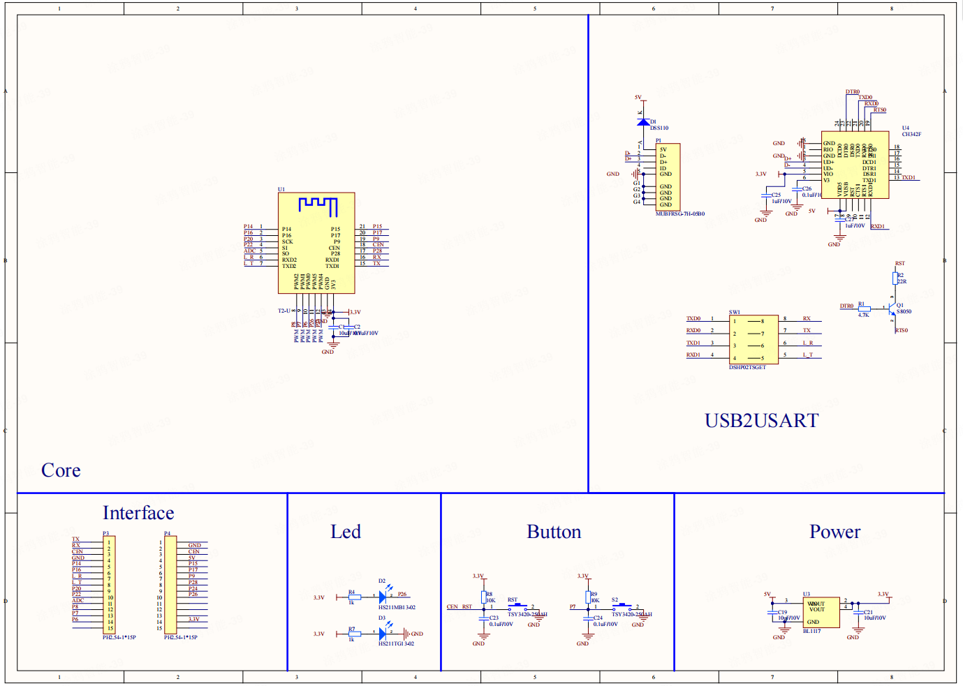
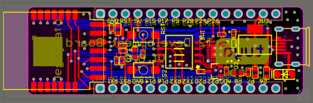
Schematic diagram and PCB
-
The schematic diagram of the board:
-
The PCB board:
-
Download schematic diagram PDF:
Flashing, authorization, and debugging
-
Flashing and authorization
The following figure shows the setup for flashing firmware using Tuya’s flashing and authorization software.
-
Flip the toggles of channels 1 and 2 on the DIP switch (SW1) to the ON position.
-
This completes the circuit between the UART1 on T2-U and the host.
-
-
View logs
-
Flip the toggles of channels 3 and 4 on the DIP switch (SW1) to the ON position.
-
This completes the circuit between the UART2 on T2-U and the host. You can view the Wi-Fi logs on the host PC.
-
Default baud rate of the serial port log: 115200.
-
USB-to-serial chip driver
Download the USB-to-serial chip driver for your operating system.
Is this page helpful?
YesFeedbackIs this page helpful?
YesFeedback


