Contact Sensor Product Development Kit
Last Updated on : 2024-08-06 13:44:06download
This topic describes a Zigbee contact sensor demo built on top of the TuyaOS platform, featuring open/close detection, tamper alarm, button control, status indicator, and battery level reporting.
Overview
Features
- Open/close detection: Monitor the open and closed status of doors and windows, and report alarms to the main controller via Zigbee. When the status of doors and windows changes, the sensor sends an event to the gateway to inform users.
- Zigbee protocol: Wireless communication over Zigbee ensures reliable data transmission and stable connections.
- Tamper alarm: Sensors can detect any attempts to breach them. If the sensor detects any tampering or damage, it will immediately alert the gateway.
- Button control: Pair, wake up, and unpair the device using physical-button control.
- Status indicator: An LED indicator signifies the connection and operating status.
- Battery level reporting: Regularly report the battery level to help users know when to replace the battery.
Actions and behaviors
-
Device pairing
-
Press and hold the pairing button on the device for three seconds to trigger pairing mode, with the network indicator blinking quickly.
-
Pair the sensor with a gateway. See the Pairing Instructions.
-
When pairing succeeds, the network indicator stays on for three seconds before turning off, and the device appears in the mobile app.
-
When pairing times out (30 seconds by default), the network indicator stops blinking and goes to sleep.
-
-
Alarm:
-
When the door or window is opened, the status indicator blinks quickly once. If the sensor is connected to the network, it will report the open status to the gateway.
-
When the door or window is closed, the status indicator blinks quickly once. If the sensor is connected to the network, it will report the closed status to the gateway.
-
When a tamper alarm is triggered, the status indicator blinks quickly once. If the sensor is connected to the network, it will report the tamper event to the gateway.
-
When a tamper alarm is dismissed, the status indicator does not illuminate. If the sensor is connected to the network, it will report the tamper dismissal event to the gateway.
-
-
Button actions:
-
Pressing the button turns on the network status indicator, while releasing it turns off the indicator and reports the battery level.
-
Pressing and holding the button turns on the network status indicator, while releasing it within three seconds turns off the indicator. When users press and hold the button for over three seconds, the device enters pairing mode, indicated by a rapid blinking light.
-
-
Status indication: The LED indicator behaves according to the device status and network connection.
-
When the device is powered on, the network indicator stays on for three seconds.
-
During pairing, the network indicator blinks quickly.
-
When pairing times out, the network indicator turns off.
-
When pairing succeeds, the network indicator stays on for three seconds and then turns off.
-
-
Battery level reporting:
-
Report the battery level at 100% within five seconds after successful pairing.
-
Report the actual battery level 20 minutes after successful pairing.
-
Report the current battery level every four hours.
-
When the battery level falls below 20%, report it every hour.
-
Create product
For more information about product creation, see Create Products.
Protocol details
Zigbee basics
| Parameter | Value |
|---|---|
| Profile ID | 0x0104 |
| Device ID | 0x0402 |
Endpoint
| Endpoint | Description |
|---|---|
| 1 | The endpoint of the current contact sensor. |
Supported clusters
| Input clusters (server) | Output clusters (client) |
|---|---|
| Basic (0x0000) | OTA Upgrade (0x0019) |
| Power Configuration (0x0001) | / |
| IAS Zone (0x0500) | / |
Supported attributes and commands
Basic cluster
Attributes
| ID | Name | Data type (ID) | Range | Default |
|---|---|---|---|---|
| 0x0000 | ZCLVersion | uint8 (0x20) | 0x00 to 0xff | 0x03 |
| 0x0001 | ApplicationVersion | uint8 (0x20) | 0x00 to 0xff | For example, 0b 01 00 0001 indicates 1.0.1, that is, 0x41 represents version 1.0.1. This attribute is used for OTA updates. When an OTA update is initiated, the gateway reads the version number of the update and pushes it to the Zigbee device. After the Zigbee device is restarted after the update, the gateway reads the current version to check for the update result. The firmware can only be updated to a higher version. |
| 0x0002 | StackVersion | uint8 (0x20) | 0x00 to 0xff | 0x02 |
| 0x0003 | HWVersion | uint8 (0x20) | 0x00 to 0xff | 0x01 |
| 0x0004 | ManufacturerName | string (0x42) | 0 to 32 bytes | XXX…XXX. The value of this attribute is 16 bytes in length, consisting of an 8-byte prefix and 8-byte PID. 0 to 7 bytes: _TZ3000_. 8 to 16 bytes: The PID, the unique identifier of the Zigbee product you create on the Tuya Developer Platform. This field determines the UI and feature display on the mobile app. You can use the default PID if you do not require a custom one. |
| 0x0005 | ModelIdentifier | string (0x42) | 0 to 32 bytes | TY0203 |
| 0x0007 | PowerSource | enum8 (0x30) | 0x00 to 0xff | 0x03 |
| 0xFFFD | ClusterRevision | uint16 (0x21) | 0x0000 to 0xffff | 0x0001 |
Power Configuration
Attributes
| ID | Name | Data type (ID) | Range | Default |
|---|---|---|---|---|
| 0x0000 | MainsVoltage | uint16 (0x21) | 0x0000 to 0xffff | 0x03 |
| 0x0020 | BatteryVoltage | uint8 (0x20) | 24 to 30 (2.4V to 3.0V) | 30 |
| 0x0021 | BatteryPercentageRemaining | uint8 (0x20) | 0 to 200 (0 to 100%) | 200 |
| 0xfffd | ClusterRevision | uint16 (0x21) | 0x0000 to 0xffff | 0x0001 |
IAS Zone
Attributes
| ID | Name | Data type (ID) | Range | Default |
|---|---|---|---|---|
| 0x0000 | ZoneState | enum8 (0x30) | 0x00 to 0xff | 0x00 |
| 0x0001 | ZoneType | enum16 (0x31) | 0x0000 to 0xffff | 0x0015 |
| 0x0002 | ZoneStatus | bitmap16 (0x19) | 0x0000 to 0xffff | 0x0000 |
| 0x0010 | IAS_CIE_Address | IEEE address (0xF0) | 8 bytes | NULL |
| 0x0011 | ZoneID | uint8 (0x20) | 0x00 to 0xff | 0x0000 |
| 0xFFFD | ClusterRevision | uint16 (0x21) | 0x0000 to 0xffff | 0x0001 |
Commands
| ID | Name | Direction | Description |
|---|---|---|---|
| 0x00 | Zone Status Change Notification | Server to client | The Zigbee device reports alarm messages to the gateway. |
| 0x01 | Zone Enroll Request | Server to client | The Zigbee device requests the Zone ID from the gateway. |
| 0x00 | Zone Enroll Response | Client to server | The gateway returns the Zone ID to the Zigbee device. |
OTA cluster
Attributes
| ID | Name | Data type (ID) | Range | Default |
|---|---|---|---|---|
| 0x0000 | UpgradeServerID | EUI64 (0xF0) | / | 0xffffffffffffffff |
| 0x0001 | FileOffset | uint32 (0x23) | / | 0x00000000 |
| 0x0002 | CurrentFileVersion | uint32 (0x23) | / | 0x00000040 |
| 0x0006 | ImageUpgradeStatus | enum8 (0x30) | / | 0x00 |
| 0x0007 | Manufacturer ID | uint16 (0x21) | / | 0x1002 |
| 0x0008 | Image Type ID | uint16 (0x21) | / | 0x1602 |
| 0x0009 | MinimumBlockPeriod | uint16 (0x21) | / | 0x0000 |
| 0xfffd | ClusterRevision | uint16 (0x21) | 0x0000 to 0xffff | 0x0001 |
Commands
| ID | Name | Direction |
|---|---|---|
| 0x00 | Image Notify | Server to client |
| 0x01 | Query Next Image Request | Client to server |
| 0x02 | Query Next Image Response | Server to client |
| 0x03 | Image Block Request | Client to server |
| 0x05 | Image Block Response | Server to client |
| 0x06 | Upgrade End Request | Client to server |
| 0x07 | Upgrade End Response | Server to client |
Mapping between DPs and clusters
| DP ID | DP description | Standard command |
|---|---|---|
| 1 | Contact sensor | Yes |
| 2 | Battery level | Yes |
| 4 | Tamper alarm | Yes |
DP1 Contact sensor
| Direction | Cluster ID | Attribute ID | Value |
|---|---|---|---|
| Device-to-cloud | 0x0500 | 0x0002 (ZoneStatus) | Bit0 (alarm)
|
Report 1 when the door is open and 0 when it is closed.
DP2 Battery level
| Direction | Cluster ID | Attribute ID | Value |
|---|---|---|---|
| Device-to-cloud | 0x0001 | 0x0020 (BatteryVoltage) | 0x00 to 0xff |
| Device-to-cloud | 0x0001 | 0x0021 (BatteryPercentageRemaining) | 0x00 to 0xff |
If the reported value of 0x0020 is 30, it indicates a voltage of 3.0V. If the reported value of 0x0021 is 180, it indicates a battery level of 90%.
DP4 Tamper alarm
| Direction | Cluster ID | Attribute ID | Value |
|---|---|---|---|
| Device-to-cloud | 0x0500 | 0x0002 (ZoneStatus) | Bit2 (tamper)
|
When a tamper alarm is triggered, the device reports alarmed, and when dismissed, it reports not alarmed.
Default heartbeat
The heartbeat packet is sent every four hours by reporting the battery level. See DP2 Battery level.
Build and flash firmware
Build firmware
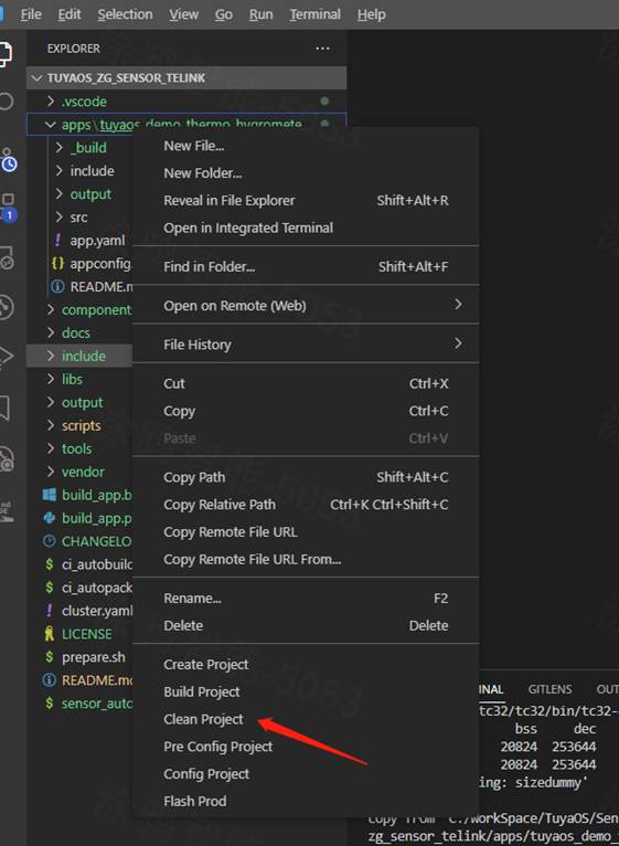
-
Open your product development kit in Visual Studio Code and expand the
software/TuyaOS/appsfolder in the left navigation pane. The demoprojectfolder will appear.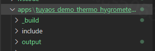
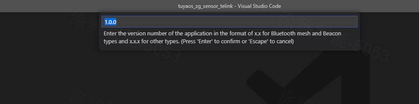
-
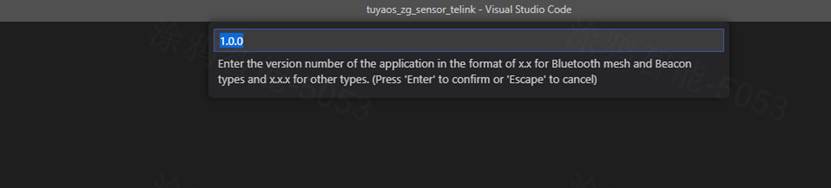
Right-click the folder and choose Build Project. Enter the version number of the build in the format
x.x.x, and hit the Enter key to confirm.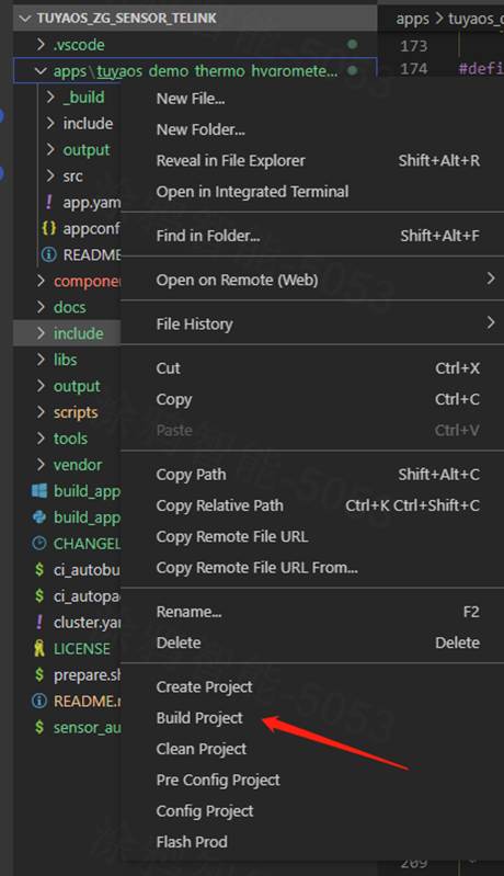
-
Once the build is finished, the console will print the following information.
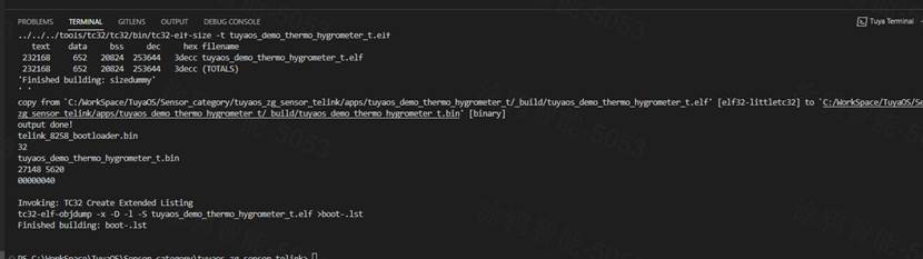
The build output is found in
apps/*product name*/output, where QIO is for production and UG is for an OTA update.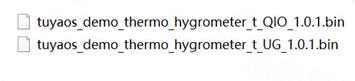
-
Clear the build cache. Before building the Telink firmware, it is recommended to select Clean Project, enter a version number, and then press Enter to clear the build cache.
Flash firmware
- Use the chip vendor’s flashing tool, found in
TLSR8258_3.8.1\software\TuyaOS\docs\, to upload firmware to Telink chips. - For more information about the flashing tools from Tuya and Silicon Labs, see Flash Firmware and Authorize Module.
Routine development
Configure basic information
Configure product features
You can configure the supported features in the sensor_app_config.h file within the include folder. To enable a feature, set it to 1. Otherwise, it is disabled. The product routine comes with essential features enabled by default and includes the necessary components. To implement the disabled features, contact the product manager. The following features are enabled for the sensor by default:
#define APP_KEY_SUPPORT                          1
#define APP_LED_SUPPORT                          1
#define APP_BATTERY_SUPPORT                      1
#define APP_GPIO_ALARM_SUPPORT                   1
#define APP_IAS_ZONE_SUPPORT                     1
#define APP_ILLUM_SUPPORT                        0
#define APP_PIR_SUPPORT                          0
#define APP_TEMPERATURE_HUMIDITY_SUPPORT         0
Configure device registration
In the app_dev_register.c file within the project’s src folder, you can modify the registered device information, including device ID, cluster, and attribute.
Add or remove the registered server cluster, as shown below.
// server cluster list
CONST TAL_CLUSTER_T app_server_cluster_list[] = {
    DEF_CLUSTER_IDENTIFY_CLUSTER_ID(identify_attr_list)
    DEF_CLUSTER_POWER_CLUSTER_ID(power_attr_list)
    DEF_CLUSTER_IAS_ZONE_CLUSTER_ID(ias_zone_attr_list)
    DEF_CLUSTER_TEMP_MEASUREMENT_CLUSTER_ID(temperature_attr_list)
    DEF_CLUSTER_RELATIVE_HUMIDITY_MEASUREMENT_CLUSTER_ID(humidity_attr_list)
    DEF_CLUSTER_ILLUM_MEASUREMENT_CLUSTER_ID(illum_measurement_attr_list)
    DEF_CLUSTER_TUYA_SENSOR_CLUSTER_ID(tuya_sensor_server_attr_list)
};
Modify the registered endpoint and device ID, as shown below.
//endpoint descriptor
TAL_ENDPOINT_T dev_endpoint_desc[] = {
    {1, ZHA_PROFILE_ID, ZG_DEVICE_ID_IAS_ZONE, SERVER_CLUSTER_NUM, (TAL_CLUSTER_T *)&app_server_cluster_list[0], 0, NULL},
};
Modify firmware information
In the app_config.yaml file within the project directory, configure information including the PID, model ID, and device type. Two configuration modes are available for this file. Choose the one that suits your needs. The content and function of the file are as follows:
#######################################################################
# COMPATIBILITY of [Tuya mode]
# For the use of Tuya redefined attributes:
# [cluster:0x0000,attribute:0x0004] Tuya manufacturer name
# [cluster:0x0000,attribute:0x0005] Tuya model ID
########################################################################
Firmware_Information:
  description: "this is a demo project"
  device_role: "router"   # router/sleep_end_dev
  image_type: 0x1602
  manufacture_id: 0x1002
  model_id: "TS0505B"
  manufacture_name: "_TZ3210_hxyvqfuz" # capacity+pid
  module_name: "ZSU"
  chip_id: "efr32mg21a020f1024im32" # efr32mg21a020f1024im32/efr32mg21a020f768im32


########################################################################
# COMPATIBILITY of [Zigbee standard mode]
# For the use of ZCL standard attributes:
# [cluster:0x0000,attribute:0x0004] ManufacturerName
# [cluster:0x0000,attribute:0x0005] ModelIdentifier
########################################################################
# Firmware_Information:
#   description: "this is a demo project"
#   device_role: "router"   # router/sleep_end_dev
#   image_type: 0x1602
#   manufacture_id: 0x1002
#   model_id: "custom"
#   manufacture_name: "custom"
#   product_id: "bhzkbugw"
#   capacity: "_TZ3210_"
#   product_type: "TS0502B"
#   module_name: "ZSU"
#   chip_id: "efr32mg21a020f1024im32" # efr32mg21a020f1024im32/efr32mg21a020f768im32
To customize the model_id and manufacture_name attributes, you must select the second mode and specify capacity, product_type, and product_id.
| Name | Feature |
|---|---|
| description | The product description. |
| device_role | The device role, with router for a standard power router device and sleep_end_dev for a low power end device. Be cautious when making changes. |
| image_type | The firmware information, used to verify OTA updates. |
| manufacture_id | The manufacturer ID, used to verify OTA updates. |
| model_id | The device model, used to identify features after the device connects to a Tuya-enabled gateway. Be cautious when making changes. |
| manufacture_name | A value that combines the product capability value and Tuya’s PID, separated by an underscore (_), for example, _TZ3210_hxyvqfuz. |
| module_name | The module model, indicating which module the product uses. |
| chip_id | The chip model, indicating which chip the product uses. Do not change this field. |
| capacity | The capability value of a Tuya-enabled product. Do not change this field. If you do need to change this field, contact the product manager. |
| product_type | The device model, used to identify features after the device connects to a Tuya-enabled gateway. Be cautious when making changes. |
| product_id | The product ID (PID) assigned by Tuya. It is currently set to a default PID, which will be replaced with a new one during flashing. |
Configure components
The following lists the required components and their configuration.
Common component
Configure the common component tbl_common in the tbl_common.h file. The available options are as follows:
| Item | Feature |
|---|---|
| IAS_ZONE_ENDPOINT | The default endpoint for IAS Zone. It is recommended to leave it as is. |
| MANUFACTURER_CODE | The manufacturer code used for manual packet assembly and transmission. It is recommended to leave it as is. |
| IAS_ZONE_TYPE | IAS Zone Type. It is recommended to leave it as is. |
| DEFAULT_TX_POWER | The device’s transmit power. Change it based on your hardware. |
| BEACON_SEND_INTERVAL_200MS | The beacon transmission interval for network scanning. This option is usually unnecessary. |
| ZIGBEE_RESET_TIME_MS | The duration for pressing and holding the reset button, defaulting to three seconds. |
| ZIGBEE_JOIN_TIMEOUT_MS | The pairing timeout, defaulting to 30 seconds. |
Battery component for application layer
Configure the battery component tbl_battery in the tbl_battery_config.h file. The available options are as follows:
| Item | Feature |
|---|---|
| TBL_BAT_INFO_FIRST_RPT_REAL_VAL_TIME | The first time the actual battery level is reported after pairing, in milliseconds, defaulting to 20 minutes. |
| TBL_BAT_INFO_WAITTING_SILENCE_TIME | Not supported. No configuration required. |
| TBL_BAT_INFO_MAX_PERIOD_TIME | The frequency of battery level acquisition, in milliseconds, defaulting to one hour. |
| BATTTERY_HEARTBEAT_INTERVAL | The heartbeat interval, in milliseconds, defaulting to four hours. |
Battery component for adaptation layer
Configure the battery component tdl_battery in the tdl_battery_config.h file. The available options are as follows:
| Item | Feature |
|---|---|
| TDL_BATTERY_DRIVER_TYPE | The driver type for battery level acquisition. Only ADC sampling is supported. |
| TDL_BAT_INFO_ADC_PIN | The voltage acquisition pin. When internal sampling is selected, set this to 0. |
| TDL_BAT_INFO_ADC_CH_ID TDL_BAT_INFO_ADC_CH_LIST TDL_BAT_INFO_ADC_CH_NUM TDL_BAT_INFO_ADC_WIDTH TDL_BAT_INFO_ADC_FREQ TDL_BAT_INFO_ADC_MODE TDL_BAT_INFO_ADC_REF_VOL | ADC parameter configurations, which cannot be changed. |
| TDL_BAT_INFO_ADC_TYPE | The battery sampling type. When internal sampling is selected, the VCC supply voltage is measured. When external sampling is selected, the voltage on the acquisition pin is measured. |
| TDL_BAT_INFO_MIN_VOLT TDL_BAT_INFO_MAX_VOLT | The maximum and minimum voltage values. The component for Tuya’s business logic layer calculates the voltage-to-power conversion table accordingly. When both macros are set to 0, the default voltage-to-power conversion table is used. |
| BATTERY_DEFAULT_TABLE | The default voltage-to-power conversion table. |
Configure pins
Configure buttons
Configure the button I/O pin in the sensor_app_config.h file within the product’s include folder, as shown below.
//key driver init info
#define KEY_PIN                                 TUYA_GPIO_NUM_17
#define KEY_IRQ_MODE                            TUYA_GPIO_LEVEL_LOW
Configure indicators
Configure the indicator I/O pin in the sensor_app_config.h file within the product’s include folder, as shown below.
#define LED_SUM                                  2

#define LED_STATUS_PIN                           (UINT32_T)TUYA_GPIO_NUM_1
#define LED_STATUS_LEVEL                         LED_HIGH_ACTIVE
#define LED_STATUS_STATRT_STATE                  LED_ST_OFF
#define LED_STATUS_COMPLETE_CB                   (NULL)      //Optional configuration

#define LED_NET_PIN                              (UINT32_T)TUYA_GPIO_NUM_0
#define LED_NET_LEVEL                            LED_HIGH_ACTIVE
#define LED_NET_STATRT_STATE                     LED_ST_OFF
#define LED_NET_COMPLETE_CB                      (NULL)
Configure alarm I/O
You can configure the alarm I/O in the sensor_app_config.h file within the include folder. Modify the I/O configuration for gpio alarm and tamper, as shown below:
//GPIO alarm
#define GPIO_SENSOR_ALARM_1_ENABLE               TRUE
#define GPIO_SENSOR_ALARM_1_PIN                  TUYA_GPIO_NUM_18
#define GPIO_SENSOR_ALARM_1_LEVEL                TUYA_GPIO_LEVEL_HIGH

#define GPIO_SENSOR_TAMPER_ENABLE                TRUE
#define GPIO_SENSOR_TAMPER_PIN                   TUYA_GPIO_NUM_19
#define GPIO_SENSOR_TAMPER_LEVEL                 TUYA_GPIO_LEVEL_HIGH

#define GPIO_SENSOR_TROUBLE_ENABLE               FALSE
#define GPIO_SENSOR_TROUBLE_PIN                  TUYA_GPIO_NUM_14
#define GPIO_SENSOR_TROUBLE_LEVEL                TUYA_GPIO_LEVEL_HIGH
Configure component I/O
See Configure Components.
Pin mapping between Telink and Tuya
The pin mapping for the Telink platform is as follows. TUYA_GPIO_NUM_0 corresponds to PA0, and so on.
STATIC CONST UINT32_T tkl_gpio_list[] = {
    GPIO_PA0, GPIO_PA1, GPIO_PA2, GPIO_PA3, GPIO_PA4, GPIO_PA5, GPIO_PA6, GPIO_PA7, // 0 - 7 //
    GPIO_PB0, GPIO_PB1, GPIO_PB2, GPIO_PB3, GPIO_PB4, GPIO_PB5, GPIO_PB6, GPIO_PB7, // 8 - 15 //
    GPIO_PC0, GPIO_PC1, GPIO_PC2, GPIO_PC3, GPIO_PC4, GPIO_PC5, GPIO_PC6, GPIO_PC7, // 16 - 23 //
    GPIO_PD0, GPIO_PD1, GPIO_PD2, GPIO_PD3, GPIO_PD4, GPIO_PD5, GPIO_PD6, GPIO_PD7, // 24 - 31 //
    GPIO_PE0, GPIO_PE1, GPIO_PE2, GPIO_PE3, // 32 - 35//
};
Pin mapping between Silicon Labs MG21 and Tuya
The pin mapping for the Silicon Labs MG21 is as follows. TUYA_GPIO_NUM_0 corresponds to PA0, and so on.
#define GPIO_PA0    0
#define GPIO_PA1    1
#define GPIO_PA2    2
#define GPIO_PA3    3
#define GPIO_PA4    4
#define GPIO_PA5    5
#define GPIO_PA6    6
#define GPIO_PB0    7
#define GPIO_PB1    8
#define GPIO_PC0    9
#define GPIO_PC1    10
#define GPIO_PC2    11
#define GPIO_PC3    12
#define GPIO_PC4    13
#define GPIO_PC5    14
#define GPIO_PD0    15
#define GPIO_PD1    16
#define GPIO_PD2    17
#define GPIO_PD3    18
#define GPIO_PD4    19
Support and help
If you have any problems with TuyaOS development, you can post your questions in the Tuya Developer Forum.
Is this page helpful?
YesFeedbackIs this page helpful?
YesFeedback


