Socket Product Development Kit
Last Updated on : 2024-08-06 13:31:28download
This topic describes a Zigbee socket demo built on top of the TuyaOS platform.
Overview
-
On/off control.
- Control methods:
- Local control using the device’s button.
- Remote control using the app panel.
- Status sync: The device status, including the relay and indicator, is synced with the app panel.
- All on/off: Turn on or off multiple switches simultaneously using the app panel.
- Control methods:
-
Set the LED indicator.
-
Turn off the indicator: The relay indicator is solid off.
-
Indicate the on/off state: The indicator on/off is aligned with the device’s on/off state.
-
Indicate the device’s position: The indicator functions contrary to the device’s on/off state, signaling the position of the device in the dark.
Once the settings are confirmed in the mobile app, they take effect immediately.
-
-
Relay power-on state (main control).
- Off: The device powers on in Off mode, with the relay open and load turned off.
- On: The device powers on in On mode, with the relay closed and load turned on.
- Memory: The device powers on in the same state it was in before being turned off.
-
Countdown timer.
Users specify a time delay. After the timer is done, the device automatically turns on or off based on its current on/off state. If the device is on now, it will be turned off after the timer is done. If the device is off now, it will be turned on after the timer is done.
The setting is a one-time event. If a switch has multiple gangs, users can set a time delay for each gang.
The countdown will reset when the following occurs:
- The countdown command is set to 0.
- During the countdown, the device’s on/off status changes due to local button control, remote control through the app, or schedule execution.
- The device is powered off and then on, or the module restarts.
After the countdown starts, the device regularly reports the remaining time to sync with the app panel for UI updates.
Features
- Control the device remotely using the app or locally with the button.
- Zigbee protocol: Wireless communication over Zigbee ensures reliable data transmission and stable connections.
- Button control: Pair and unpair the device using physical-button control.
- Status indicator: An LED indicator signifies the connection and operating status.
Actions and behaviors
-
Device pairing
-
Press and hold the pairing button on the device for three seconds to trigger pairing mode, with the network indicator blinking quickly.
-
Pair the socket with a gateway. See the Pairing Instructions.
-
When pairing succeeds, the network indicator turns off and the device appears in the mobile app.
-
When pairing fails or times out (300 seconds by default), the network indicator stops blinking and stays on.
-
-
Button actions:
-
When users press and release the button within two seconds, the relay and indicator will toggle.
-
When users press and hold the button for more than two seconds but less than five seconds, the device does not respond. When users press and hold the button for over five seconds, the device enters pairing mode, indicated by a rapid blinking light.
-
-
Network status indication: The LED indicator behaves according to the device status and network connection.
- During pairing, the network indicator blinks quickly.
- When pairing times out, the network indicator turns off.
- When pairing succeeds, the network indicator stays on.
Create product
For more information about product creation, see Create Products.
Protocol details
Zigbee basics
| Parameter | Value |
|---|---|
| Profile ID | 0x0104 |
| Device ID | 0x010A |
Endpoint
| Endpoint | Description |
|---|---|
| 1 | The endpoint of the first switch. |
Supported clusters
| Input clusters (server) | Output clusters (client) |
|---|---|
| Basic (0x0000) | OTA Upgrade (0x0019) |
| Identify (0x0003) | / |
| Groups (0x0004) | / |
| Scenes (0x0005) | / |
| On/Off (0x0006) | / |
Supported attributes and commands
Basic cluster
Attributes
| ID | Name | Data type (ID) | Range | Default |
|---|---|---|---|---|
| 0x0000 | ZCLVersion | uint8 (0x20) | 0x00 to 0xff | 0x03 |
| 0x0001 | ApplicationVersion | uint8 (0x20) | 0x00 to 0xff | For example, 0b 01 00 0001 indicates 1.0.1, that is, 0x41 represents version 1.0.1. This attribute is used for OTA updates. When an OTA update is initiated, the gateway reads the version number of the update and pushes it to the Zigbee device. After the Zigbee device is restarted after the update, the gateway reads the current version to check for the update result. The firmware can only be updated to a higher version. |
| 0x0002 | StackVersion | uint8 (0x20) | 0x00 to 0xff | 0x02 |
| 0x0003 | HWVersion | uint8 (0x20) | 0x00 to 0xff | 0x01 |
| 0x0004 | ManufacturerName | string (0x42) | 0 to 32 bytes | XXX…XXX. The value of this attribute is 16 bytes in length, consisting of an 8-byte prefix and 8-byte PID. 0 to 7 bytes: _TZ3000_. 8 to 16 bytes: The PID, the unique identifier of the Zigbee product you create on the Tuya Developer Platform. This field determines the UI and feature display on the mobile app. You can use the default PID if you do not require a custom one. |
| 0x0005 | ModelIdentifier | string (0x42) | 0 to 32 bytes | TS000x (switch with neutral), connected to a Tuya-enabled Zigbee gateway for use. x represents the number of channels. For example, TS0002 represents a 2-gang switch with neutral. |
| 0x0007 | PowerSource | enum8 (0x30) | 0x00 to 0xff | 0x01 |
| 0xFFFD | ClusterRevision | uint16 (0x21) | 0x0000 to 0xffff | 0x0001 |
Commands
| ID | Name | Direction | Description |
|---|---|---|---|
| 0x00 | Reset to Factory Defaults | Client to server | Factory reset |
On/Off cluster
Attributes
| ID | Name | Data type (ID) | Range | Default |
|---|---|---|---|---|
| 0x0000 | OnOff | bool (0x10) |
|
0x00 |
| 0x4001 | OnTime | uint16 (0x21) | 0 to 43200 | 0x0000 |
| 0x4002 | OffWaitTime | uint16 (0x21) | 0 to 43200 | 0x0000 |
| 0x8002 | Power-on state (main control) (Tuya-specific attribute) | enum8 (0x30) |
|
0x00 |
| 0x8001 | Indicator state (Tuya-specific attribute) | enum8 (0x30) |
|
0x00 |
Commands
| ID | Name | Direction |
|---|---|---|
| 0x00 | Off | Client to server |
| 0x01 | On | Client to server |
| 0x00 | Toggle | Client to server |
| 0x03 | On with timed off | Client to server |
Mapping between DPs and clusters
| DP ID | DP description | Standard command | Endpoint |
|---|---|---|---|
| 1 | Switch 1 | Yes | 1 |
| 2 | Switch 2 | Yes | 2 |
| 9 | Switch 1 countdown timer | Yes | 1 |
| 10 | Switch 2 countdown timer | Yes | 2 |
| 27 | Power-on state (main control) | No | 1 |
| 28 | Indicator state | No | 1 |
DP1 Switch 1 to DP2 Switch 2
Send the On, Off, or Toggle command to the Zigbee device. The Zigbee device reports on/off status using the ZCL on/off attribute.
| Direction | Cluster | ID | Command/Attribute ID | Value |
|---|---|---|---|---|
| Cloud-to-device | 0x0006 |
On/Off |
|
/ |
| Device-to-cloud | 0x0006 |
On/Off | 0x0000: On/Off |
|
DP9 Switch 1 countdown timer to DP10 Switch 2 countdown timer
| Direction | Cluster | ID | Command/Attribute ID | Value |
|---|---|---|---|---|
| Cloud-to-device | 0x0006 |
On/Off | 0x42: On with timed off |
Payload |
Payload format: On/off Control (0x00). The specified times for On Time and Off Wait Time must be identical. For example, send a 60-second countdown command to the device with the following payload:
-
On/off Control:
0x00 -
On Time:
0x003c -
Off Wait Time:
0x003c
DP27 Power-on state (main control)
| Direction | Cluster ID | Command/Attribute ID | Value |
|---|---|---|---|
| Cloud-to-device | 0x0006: On/Off |
0x8002 (Tuya-specific attribute) |
|
| Device-to-cloud | 0x0006: On/Off |
0x8002 (Tuya-specific attribute) |
|
DP28 Indicator status
| Direction | Cluster ID | Command/Attribute ID | Value |
|---|---|---|---|
| Cloud-to-device | 0x0006: On/Off |
0x8001 (Tuya-specific attribute) |
|
| Device-to-cloud | 0x0006: On/Off |
0x8001 (Tuya-specific attribute) |
|
Build and flash firmware
Build firmware
-
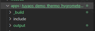
Open your product development kit in Visual Studio Code and expand the
software/TuyaOS/appsfolder in the left navigation pane. The demoprojectfolder will appear.
-
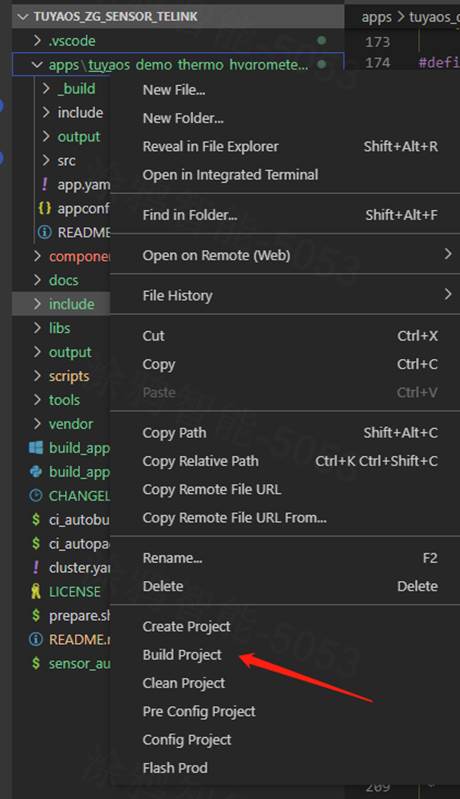
Right-click the folder and choose Build Project. Enter the version number of the build in the format
x.x.x, and hit the Enter key to confirm.

-
Once the build is finished, the console will print the following information.

The build output is found in
apps/*product name*/output, where QIO is for production and UG is for an OTA update.
-
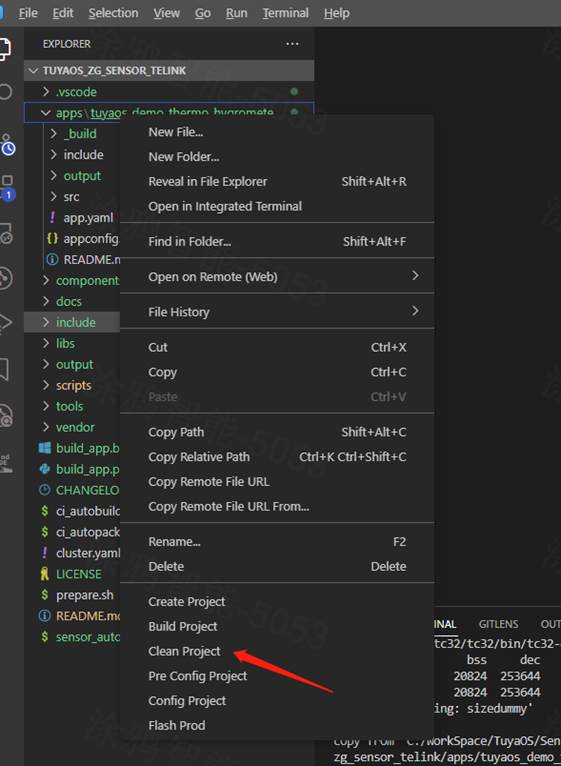
Clear the build cache. Before building the Telink firmware, it is recommended to select Clean Project, enter a version number, and then press Enter to clear the build cache.


Flash firmware
- Use the chip vendor’s flashing tool, found in
TLSR8258_3.8.1\software\TuyaOS\docs\, to upload firmware to Telink chips. - For more information about the flashing tools from Tuya and Silicon Labs, see Flash Firmware and Authorize Module.
Routine development
Configure basic information
Configure product features
You can configure the supported features in the app_configuration.h file within the include folder. To enable a feature, set it to 1. Otherwise, it is disabled. The product routine comes with essential features enabled by default and includes the necessary components. If you need an optional feature, add the necessary components before enabling it. The following features are enabled for the socket by default:
#define BUTTON_ENABLE                              1    //0: disable 1: button enable
#define COUNTDOWN_ENABLE                           1    //0: disable 1: countdown enable
#define REPORT_STRATEGY_ENABLE                     1    //0: disable 1: report attribute strategy enable
#define ZERO_CROSSING_DETECT_ENABLE                1    //0: disable 1: Zero-crossing detection enable
#define DELAY_CLOSE_ENABLE                         1    //0: disable 1: delay close relay enable
#define LED_MODE_ENABLE                            1    //0: disable 1: led mode enable
#define TOT_RELAY_STATUS_ENABLE                    1    //0: disable 1: relay status power on enable
#define SUB_RELAY_UNIT_ENABLE                      1    //0: disable 1: sub relay status power on enable
Configure device registration
In the app_dev_register.c file within the project’s src folder, you can modify the registered device information, including device ID, cluster, and attribute.
Modify the registered server cluster, as shown below.
// server cluster for the first endpoint
CONST TAL_CLUSTER_T g_server_cluster_id[] = {
    DEF_CLUSTER_IDENTIFY_CLUSTER_ID(identify_attr_list)
    DEF_CLUSTER_GROUPS_CLUSTER_ID(group_attr_list)
    DEF_CLUSTER_SCENES_CLUSTER_ID(scene_attr_list)
    DEF_CLUSTER_ON_OFF_CLUSTER_ID(onoff_attr_list)
    CLUSTER_TUYA_ELECTRICIAN_CLUSTER_ID_DEF
    CLUSTER_TUYA_COMMON_CLUSTER_ID_DEF
};
-
If the new cluster and attributes apply only to the first endpoint, add them to
g_server_cluster_id. -
If the new cluster and attributes apply to all endpoints, add them to both
g_server_cluster_idandg_server_cluster_id_except_ep1.
// server cluster except for the first endpoint
CONST TAL_CLUSTER_T g_server_cluster_id_except_ep1[] = {
    DEF_CLUSTER_IDENTIFY_CLUSTER_ID(identify_attr_list)
    DEF_CLUSTER_GROUPS_CLUSTER_ID(group_attr_list)
    DEF_CLUSTER_SCENES_CLUSTER_ID(scene_attr_list)
    DEF_CLUSTER_ON_OFF_CLUSTER_ID(onoff_attr_list_except_ep1)
    CLUSTER_TUYA_ELECTRICIAN_CLUSTER_ID_DEF_EXCEPT_EP1
};
In the app_dev_register.h file within the project’s include folder, you can modify the registered endpoint and device ID.
#define EP_VALUE_TABLE              {1, 2, 3, 4, 5, 6, 7, 8, 9, 10}      ///endpoint
#define DEV_DESCRIPTION_DEF(ep)                     DEV_SERVER_DESC(0x010A, ep)
#define DEV_DESCRIPTION_EXCEPT_EP1_DEF(ep)          DEV_SERVER_DESC_EXCEPT_EP1(0x010A, ep)
Modify firmware information
In the app_config.yaml file within the project directory, configure information including the PID, model ID, and device type. Two configuration modes are available for this file. Choose the one that suits your needs. The content and function of the file are as follows:
#######################################################################
# COMPATIBILITY of [Tuya mode]
# For the use of Tuya redefined attributes:
# [cluster:0x0000,attribute:0x0004] Tuya manufacturer name
# [cluster:0x0000,attribute:0x0005] Tuya model ID
########################################################################
Firmware_Information:
  description: "this is a demo project"
  device_role: "router"   # router/sleep_end_dev
  image_type: 0x1602
  manufacture_id: 0x1002
  model_id: "TS0505B"
  manufacture_name: "_TZ3210_hxyvqfuz" # capacity+pid
  module_name: "ZSU"
  chip_id: "efr32mg21a020f1024im32" # efr32mg21a020f1024im32/efr32mg21a020f768im32


########################################################################
# COMPATIBILITY of [Zigbee standard mode]
# For the use of ZCL standard attributes:
# [cluster:0x0000,attribute:0x0004] ManufacturerName
# [cluster:0x0000,attribute:0x0005] ModelIdentifier
########################################################################
# Firmware_Information:
#   description: "this is a demo project"
#   device_role: "router"   # router/sleep_end_dev
#   image_type: 0x1602
#   manufacture_id: 0x1002
#   model_id: "custom"
#   manufacture_name: "custom"
#   product_id: "bhzkbugw"
#   capacity: "_TZ3210_"
#   product_type: "TS0502B"
#   module_name: "ZSU"
#   chip_id: "efr32mg21a020f1024im32" # efr32mg21a020f1024im32/efr32mg21a020f768im32
To customize the model_id and manufacture_name attributes, you must select the second mode and specify capacity, product_type, and product_id.
| Name | Feature |
|---|---|
| description | The product description. |
| device_role | The device role, with router for a standard power router device and sleep_end_dev for a low power end device. Be cautious when making changes. |
| image_type | The firmware information, used to verify OTA updates. |
| manufacture_id | The manufacturer ID, used to verify OTA updates. |
| model_id | The device model, used to identify features after the device connects to a Tuya-enabled gateway. Be cautious when making changes. |
| manufacture_name | A value that combines the product capability value and Tuya’s PID, separated by an underscore (_), for example, _TZ3210_hxyvqfuz. |
| module_name | The module model, indicating which module the product uses. |
| chip_id | The chip model, indicating which chip the product uses. Do not change this field. |
| capacity | The capability value of a Tuya-enabled product. Do not change this field. If you do need to change this field, contact the product manager. |
| product_type | The device model, used to identify features after the device connects to a Tuya-enabled gateway. Be cautious when making changes. |
| product_id | The product ID (PID) assigned by Tuya. It is currently set to a default PID, which will be replaced with a new one during flashing. |
Configure pins
Configure hardware peripheral I/O pins in the app_configuration.h file within the product’s include folder, as shown below.
-
Configure the button:
//Button GPIO config #define KEY_GPIO_CFG \ { \ .pin_num = APP_GPIO_PD2, \ .pin_active_level = TUYA_GPIO_LEVEL_LOW \ }, \ { \ .pin_num = APP_GPIO_PB4, \ .pin_active_level = TUYA_GPIO_LEVEL_LOW \ } \ -
Configure the indicator:
//LED GPIO config #define LED_GPIO_CFG \ { \ .led_pin_num = APP_GPIO_PD7, \ .led_active_level = LED_LOW_ACTIVE, \ .led_init_st = LED_ST_OFF, \ .led_blink_stop_callback = led_stop_blink_callback \ }, \ { \ .led_pin_num = APP_GPIO_PD4, \ .led_active_level = LED_LOW_ACTIVE, \ .led_init_st = LED_ST_OFF, \ .led_blink_stop_callback = led_stop_blink_callback \ } \ -
Configure the network indicator:
//Network LED GPIO config #define NET_LED_GPIO_CFG \ { \ .led_pin_num = APP_GPIO_PC3, \ .led_active_level = LED_LOW_ACTIVE, \ .led_init_st = LED_ST_OFF, \ .led_blink_stop_callback = led_stop_blink_callback \ } \ -
Configure the relay:
//Relay GPIO config #define RELAY_GPIO_CFG \ { \ .led_pin_num = APP_GPIO_PA0, \ .led_active_level = LED_HIGH_ACTIVE, \ .led_init_st = LED_ST_OFF \ }, \ { \ .led_pin_num = APP_GPIO_PA1, \ .led_active_level = LED_HIGH_ACTIVE, \ .led_init_st = LED_ST_OFF \ } \ -
Configure the zero-crossing detection pin:
//Zero-crossing detection GPIO config
#define ZERO_GPIO_CFG    \
    { \
        .pin_num = APP_GPIO_PB6, \
        .pin_active_level = TUYA_GPIO_LEVEL_HIGH \
    } \
Support and help
If you have any problems with TuyaOS development, you can post your questions in the Tuya Developer Forum.
Is this page helpful?
YesFeedbackIs this page helpful?
YesFeedback


