CL-BPT8-02 Datasheet
This topic describes Tuya’s proprietary CL-BPT8-02 radar and Bluetooth low energy (LE) printed circuit board assembly (PCBA). It consists of a highly integrated Bluetooth chip, a radar IC, and a few peripheral circuits. It has built-in Bluetooth protocol stacks and a rich set of library functions.
Overview
CL-BPT8-02 is built around a 32-bit MCU, Bluetooth 5.4 LE, 5.8 GHz radio, 64 KB SRAM, and 8 KB retention SRAM. It has 16 KB OTP and 5 GPIOs. It uses radar sensing and is not affected by ambient temperature, humidity, airflow, dust, noise, light and dark when working. The module has built-in multiple filtering algorithms with strong anti-interference capability, and the signal can penetrate non-metallic materials such as glass and acrylic.
Therefore, the module can be used in various scenarios such as detecting human presence or sensing moving objects, making it especially suitable for garage lighting.
Features
- Built-in low-power 32-bit MCU that also acts as an application processor
- Clock rate of 64 MHz
- Operating voltage range: 3.6V to 5.5V
- Peripherals: 5 GPIO pins
- Bluetooth LE radio frequency (RF) features
- Bluetooth LE 5.4
- RF data rate of up to 2 Mbit/s
- Transmitter (TX) power: +8 dBm
- Receiver (RX) sensitivity: -87 dBm@Bluetooth LE 1 Mbit/s
- Integrated microwave sensor (radar) with Doppler effect
- 5.8 GHz ISM band
- Sensing distance and delay can be flexibly adjusted as needed
- Self-calibration function, not affected by external interference, supporting dense distribution
- Embedded hardware Advanced Encryption Standard (AES) encryption
- The chip has a built-in low-dropout (LDO) regulator and supports a power supply with a wide voltage range
- Onboard printed circuit board (PCB) antenna
- Operating temperature range: -20°C to +85°C
Applications
- Smart garage lighting
- Smart industrial lighting
- Smart office lighting
Module interfaces
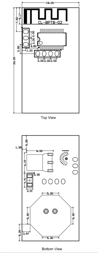
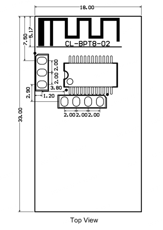
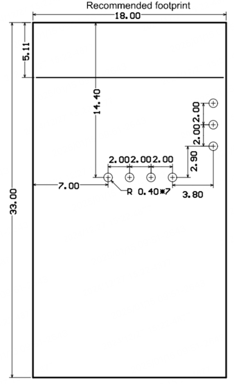
Dimensions and footprint
CL-BPT8-02 has two rows of pins with a 2.0±0.1 mm pin spacing.
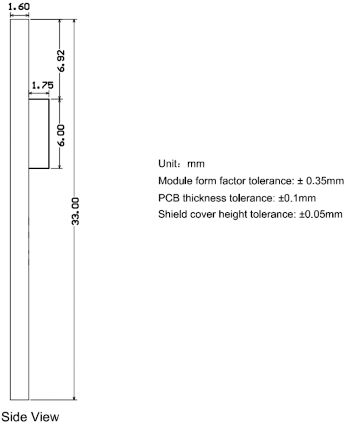
CL-BPT8-02 dimensions are 18±0.35 mm (W) × 33±0.35 mm (L) × 3.4±0.35 mm (H).
Pin definition
| Pin No. | Symbol | I/O type | Description |
|---|---|---|---|
| 1 | P02 | I/O | Support hardware PWM, corresponding to P02 (Pin 7) on the IC. |
| 2 | P03 | I/O | Support hardware PWM, corresponding to P03 (Pin 8) on the IC. |
| 3 | P06 | I/O | Support hardware PWM, corresponding to P06 (Pin 11) on the IC. |
| 4 | P08 | I/O | Support hardware PWM, corresponding to P08 (Pin 13) on the IC. |
| 5 | P11 | I/O | Support hardware PWM, corresponding to P11 (Pin 18) on the IC. |
| 6 | GND | P | Ground pin. |
| 7 | VCC | P | Power supply pin (5V). |
| Test pin | ADC | AO | Outputs the radar intermediate frequency signal. |
| Test pin | TX | I/O | Uart_TXD, corresponding to P04 (Pin 9) on the IC. |
| Test pin | RX | I/O | Uart_RXD, corresponding to P05 (Pin 10) on the IC. |
Pindicates the power pin, I/O indicates the input and output pin, and AO indicates the analog output signal.- If you have requirements for the number of PWM output control channels and color temperature, please contact Tuya’s business personnel.
Electrical parameters
Absolute electrical parameters
| Parameter | Description | Min value | Max value | Unit |
|---|---|---|---|---|
| Ts | Storage temperature | -35 | 90 | °C |
| VCC | Supply voltage | -0.3 | 5.5 | V |
| Electrostatic discharge voltage (human body model) | TAMB-25°C | - | 2 | kV |
| Electrostatic discharge voltage (machine model) | TAMB-25°C | - | 0.5 | kV |
Operating conditions
| Parameter | Description | Min value | Typical value | Max value | Unit |
|---|---|---|---|---|---|
| Ta | Operating temperature | -20 | - | 85 | °C |
| VCC | Operating voltage | 3.6 | 5.0 | 5.5 | V |
| VIL | I/O low-level input | VSS | - | 0.9 | V |
| VIH | I/O high-level input | 2.4 | - | 3.5 | V |
| VOL | I/O low-level output | VSS | - | 0.33 | V |
| VOH | I/O high-level output | 3.0 | 3.3 | 3.5 | V |
Operating power consumption
| Symbol | Condition | Max (Typical) value | Unit |
|---|---|---|---|
| Itx | Continuous transmission, with an output power of 8 dBm | 35 | mA |
| Irx | Continuous reception | 28 | mA |
| IDC | Average value when connected over Bluetooth mesh | 27 | mA |
| IDC | Peak value when connected over Bluetooth mesh | 36 | mA |
RF parameters
Basic RF features
| Parameter | Description |
|---|---|
| Bluetooth operating frequency | 2.4 GHz ISM band |
| Radar operating frequency | 5.8 GHz ISM band |
| Wireless standard | Bluetooth LE 5.4 |
| Data transmission rate | 1 Mbit/s and 2 Mbit/s |
| Antenna type | Onboard PCB antenna. |
| Antenna gain | 0.56 dBi |
RF output power
| Parameter | Min value | Typical value | Max value | Unit |
|---|---|---|---|---|
| Bluetooth average output power | -22 | 8 | 10 | dBm |
| Bandwidth of 20 dB Bluetooth modulation signal (1 Mbit/s) | - | 2500 | - | KHz |
| Bandwidth of 20 dB Bluetooth modulation signal (2 Mbit/s) | - | 1400 | - | KHz |
| Radar transmit frequency | 5735 | - | 5840 | MHz |
| Radar transmit power | - | 0.2 | 0.5 | mW |
RF receiver (RX) sensitivity
| Parameter | Min value | Typical value | Max value | Unit |
|---|---|---|---|---|
| Bluetooth RX sensitivity at 1 Mbit/s | - | -87 | - | dBm |
| Bluetooth RX sensitivity at 2 Mbit/s | - | -82 | - | dBm |
| Bluetooth frequency offset error at 1 Mbit/s | -250 | - | +300 | KHz |
| Bluetooth frequency offset error at 2 Mbit/s | -300 | - | +200 | KHz |
| Bluetooth co-channel interference suppression | - | -6 | - | dB |
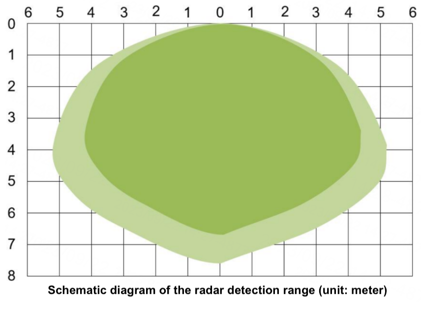
Radar detection range
The sensing sensitivity of the radar sensor can be configured through Bluetooth. Its forward limit sensing distance is 10 meters. You can appropriately adjust the actual sensing distance as needed.
The figure below is a schematic diagram of the radar detection range in a typical scenario. The higher the sensitivity, the larger the detection range. The dark area in the figure is a high-sensitivity detection area, in which objects can be completely detected. The light-colored area is a low-sensitivity detection area, in which objects can be basically detected.
Antenna information
Antenna type
The CL-BPT8-02 PCBA uses an onboard PCB antenna.
Antenna interference reduction
- The distance between the antenna (Bluetooth antenna and radar antenna) and other mental components should be at least 15 mm to provide the best radio performance. And there are no metal obstructions on the RF path.
- Try to avoid pointing the radar antenna directly toward large metal devices or pipes.
- When installing multiple PCBAs, try to make sure that the radar antennas are parallel to each other to avoid direct irradiation, and keep a distance of more than 1m between antennas.
- When the radar sensor works in low power mode, we do not recommend using it in scenarios close to switching power supply drives.
Packing and production instructions
Mechanical dimensions
The PCBA dimensions are 18±0.35 mm (W) × 33±0.35 mm (L) × 3.4±0.35 mm (H).
PCB package
Production instructions
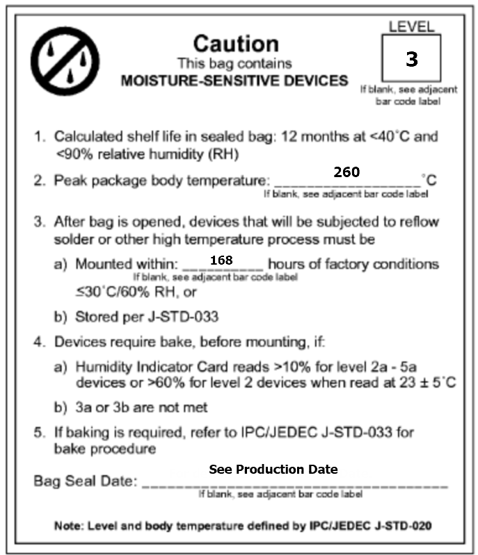
- A wave soldering device is recommended to solder Tuya’s DIP modules. Manual soldering is used only when wave soldering is unavailable. Complete soldering within 24 hours after the module is unpacked. Otherwise, place the module in a drying cupboard with a relative humidity level below 10%, or pack the module in vacuum again. Then, record the packing time and duration of exposure. The total exposure time cannot exceed 168 hours.
- Soldering device and materials:
- Wave soldering equipment
- Wave soldering fixture
- Constant-temperature soldering iron
- Tin bar, tin wire, and flux
- Thermal profiler
- Instruments or devices required for the baking process:
- Cabinet oven
- Electrostatic discharge (ESD) protection and heat-resistant trays
- ESD protection and heat-resistant gloves
- The module needs to be baked in the following cases:
- The vacuum packaging bag is damaged before unpacking.
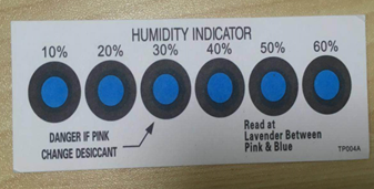
- After unpacking, no HIC is found in the packaging bag.
- After unpacking, the HIC indicates a humidity level of 10% or higher. In this case, the circle turns pink on the HIC.
- The total exposure time has lasted for over 168 hours since unpacking.
- More than 12 months have passed since the first sealing of the bag.
- The baking parameter settings are described below:
- Baking temperature: 60°C for reel packaging with relative humidity ≤ 5%. And 125°C for tray packaging with relative humidity ≤ 5% (use a heat-resistant tray, rather than plastic containers).
- Baking time: 48 hours for reel packaging and 12 hours for tray packaging.
- Temperature for triggering an alert: 65°C for reel packaging and 135°C for tray packaging.
- Production can begin after a module has cooled down to below 36°C under natural conditions.
- If a module remains unused for over 168 hours after being baked, it needs to be baked again.
- If a batch of modules is not baked after exposure for more than 168 hours, do not use wave soldering to solder them. Because these modules are level-3 moisture-sensitive devices, they are very likely to get damp when exposed beyond the allowable time. In this case, if they are soldered at high temperatures, device failure or poor soldering performance might occur.
- In the whole production process, take electrostatic discharge (ESD) protective measures.
- In order to ensure good product quality, focus on the amount of flux sprayed and peak height during production. Check whether the tin slag and copper contents in the wave soldering tank exceed the standard amount, whether the fixture opening and thickness are appropriate, and whether the oven temperature curve of the wave soldering is proper.
- With a built-in crystal oscillator, this product can generally be cleaned with an ordinary detergent or ultrasonic wave. But in some cases, vibrations generated by an ultrasonic cleaner can damage the internal structure of the crystal oscillator. If you use an ultrasonic cleaner, you need to verify in advance to make sure the crystal oscillator inside the module is protected from any possible damage.
- During product installation or processing, ultrasonic soldering is not recommended, because it might lead to excessive internal vibration or even failure of the crystal oscillator in the module.
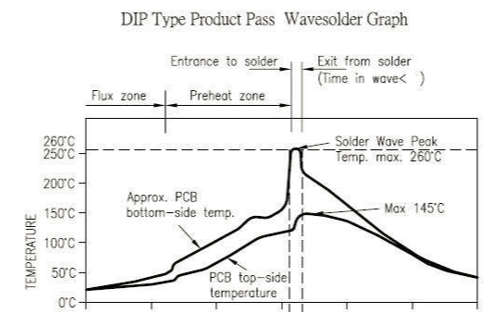
Recommended oven temperature curve and temperature
Set the oven temperatures according to the following temperature curve of wave soldering. The peak temperature is 260°C±5°C.
Oven temperature curve:
Suggestions on the soldering temperature:
| Suggestions on wave soldering | Suggestions on manual soldering | ||
|---|---|---|---|
| Preheat temperature | 80°C to 130°C | Soldering temperature | 360°C ± 20°C |
| Preheat duration | 75s to 100s | Soldering duration | Less than 3s/point |
| Contact duration at the peak | 3s to 5s | - | - |
| Solder tank temperature | 260°C ± 5°C | - | - |
| Ramp-up slope | ≤ 2°C/s | - | - |
| Ramp-down slope | ≤ 6°C/s | - | - |
Storage conditions
A delivered module must meet the following storage requirements:
-
The moisture-proof bag must be packed in vacuum and placed in an environment where the temperature is below 40°C and the relative humidity is lower than 90%.
-
The shelf life of a dry-packaged product is 12 months from the date when the product is packaged and sealed.
-
A humidity indication card (HIC) is put in the sealed package.
Module MOQ and Packaging Information
| Product model | MOQ (pcs) | Shipping packaging method | Number of modules per reel | Number of reels per carton |
|---|---|---|---|---|
| CL-BPT8-02 | 2800 | Tape and reel | 700 | 4 |
Appendix: Statement
FCC Caution: Any changes or modifications not expressly approved by the party responsible for compliance could void the user’s authority to operate this device.
This device complies with Part 15 of the FCC Rules. Operation is subject to the following two conditions: (1) This device may not cause harmful interference, and (2) this device must accept any interference received, including interference that may cause undesired operation.
Note: This device has been tested and found to comply with the limits for a Class B digital device, according to part 15 of the FCC Rules. These limits are designed to provide reasonable protection against harmful interference in a residential installation. This device generates, uses, and can radiate radio frequency energy and, if not installed and used following the instructions, may cause harmful interference to radio communications. However, there is no guarantee that interference will not occur in a particular installation.
If this device does cause harmful interference to radio or television reception, which can be determined by turning the device off and on, the user is encouraged to try to correct the interference by one or more of the following measures:
- Reorient or relocate the receiving antenna.
- Increase the separation between the device and receiver.
- Connect the device to an outlet on a circuit different from that to which the receiver is connected.
- Consult the dealer or an experienced radio/TV technician for help.
Radiation Exposure Statement
This device complies with FCC radiation exposure limits set forth for an uncontrolled rolled environment. This device should be installed and operated with a minimum distance of 20cm between the radiator and your body.
Important Note
This radio module must not be installed to co-locate and operate simultaneously with other radios in the host system except by following FCC multi-transmitter product procedures. Additional testing and device authorization may be required to operate simultaneously with other radios.
The availability of some specific channels and/or operational frequency bands are country dependent and are firmware programmed at the factory to match the intended destination. The firmware setting is not accessible to the end-user.
The host product manufacturer is responsible for compliance with any other FCC rules that apply to the host not covered by the modular transmitter grant of certification. The final host product still requires Part 15 Subpart B compliance testing with the modular transmitter installed.
The end-user manual shall include all required regulatory information/warnings as shown in this manual, including "This product must be installed and operated with a minimum distance of 20 cm between the radiator and user body".
The RF module is considered as a limited modular transmitter according to FCC rules. Even though the RF module gets an FCC ID, the host product manufacturer can not use the FCC ID on the final product directly. In these circumstances, the host product manufacturer integrator will be responsible for re-evaluating the end product (including the transmitter) and obtaining FCC authorization by a Class II permissive change application or a new application.
CE Caution: This equipment has been tested and found to comply with the limits for an EN 300 440 v2.2.1 receiver Category 3. These limits are designed to provide reasonable protection against harmful interference in a residential installation. When placed in the vicinity of other device(s) radiating in the 5735 MHz-5840 MHz band, this device will inadvertency trigger on, or will fail to switch off with its movement sensor capability being impaired. Please take appropriate measures to mitigate this eventuality.
Declaration of Conformity European Notice

Hereby, Hangzhou Tuya Information Technology Co., Ltd declares that this module product is in compliance with essential requirements and other relevant provisions of Directive 2014/53/EU,2011/65/EU. A copy of the Declaration of Conformity can be found at https://www.tuya.com

This product must not be disposed of as normal household waste, in accordance with the EU directive for waste electrical and electronic equipment (WEEE-2012/19/EU). Instead, it should be disposed of by returning it to the point of sale, or to a municipal recycling collection point.
The device could be used with a separation distance of 20cm from the human body.
Is this page helpful?
YesFeedbackIs this page helpful?
YesFeedback


