Basic Features
This topic describes the basic features in the Bluetooth generic protocol, including module initialization, device binding, and two-way data transmission between the device and the cloud, which are essential to make your product IoT-enabled.
- If your MCU does not have sufficient resources or porting SDK is not feasible, you can interface the serial protocol yourself. Note that the basic features must be implemented. Otherwise, your product will not work properly.
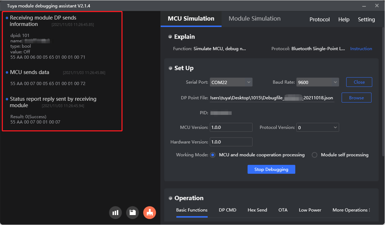
- All the protocol examples in this topic are performed on the module debugging assistant. This debugger can help you understand how data transmission works.
Module initialization
Module initialization indicates a process where a module performs the initial configuration with the information sent from the MCU.
Feature description
After the module establishes communication with the MCU, the initialization process starts. The module will send heartbeats, request product information, get the working mode, report the work status, and sync status with the MCU. After that, the module can perform binding with the mobile app, data processing, and extended features.
After power-on, the module keeps sending heartbeats to the MCU and will not proceed with the initialization process until receiving a correct response from the MCU.
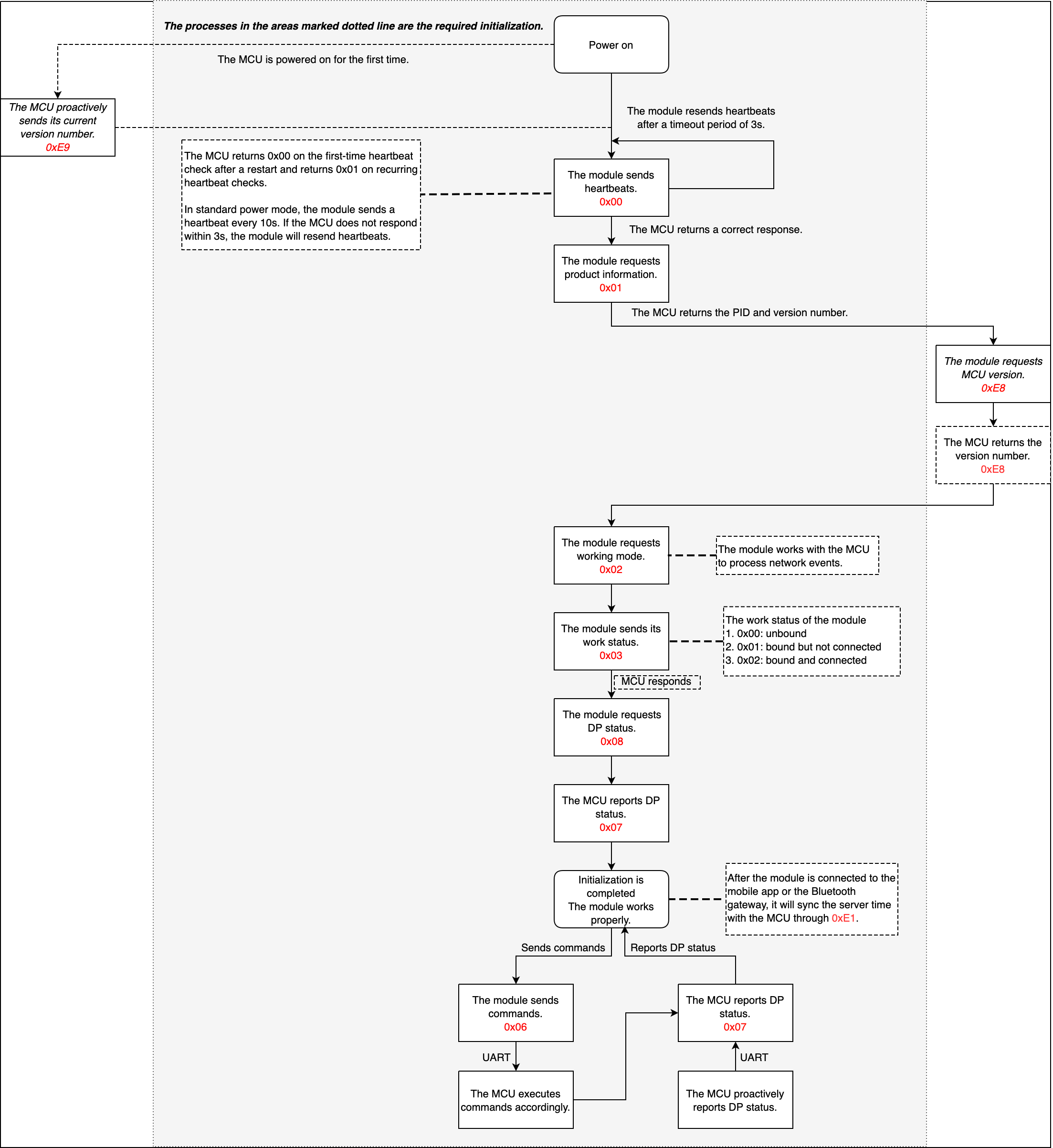
The MCU can send 0xE9 or 0xE8 or both to report its version to the module. 0xE9 and 0xE8 differ in the following aspects:
-
0xE9is used for the MCU to proactively report its version.0xE9is optional. When the module is powered on, the MCU can send0xE9to proactively report its version. -
0xE8is used for the MCU to respond to the module’s request for its version.After the MCU responds to
0x01, the module will send0xE8to request the MCU’s version if the MCU has not reported it through0xE9. After that, the MCU uses0xE8to report its current version.
After the module is connected to the mobile app or the gateway, it will send 0xE1 to sync time with the MCU. The MCU returns the required date and time format through 0xE1.
Auto-baud detection
-
The module reads the baud history saved in the flash memory.
-
The module enters the correct initialization process according to whether the baud is detected.
- If baud detected: The module sets the baud to the detected value and sends one heartbeat to the MCU with an interval of three seconds. If the MCU does not return a response, the module will enter the detection mode again.
- If baud not detected: The module enters the detection mode. It sends one heartbeat at
9600baud and waits three seconds for a response from the MCU. Then, it repeats the same heartbeat sending pattern at115200baud. If the module receives the intended response, it means the correct baud is detected. The detected baud will be used to initialize serial communication and be saved on the flash memory.
The latest firmware supports automatic baud selection from 9600 or 115200. Automatic baud detection will occur before the first initialization. It is normal to get some garbled text or startup latency.
Scenarios
The initialization is triggered after the module is restarted or reset. There can be two situations:
-
The module is not bound: The configuration of the product information and working mode is completed. The module reports its current work status to the MCU and is ready for pairing.
-
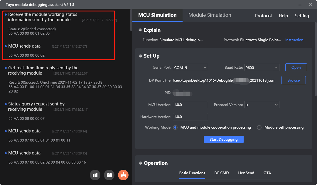
The module is bound: The configuration of the product information and working mode is completed. The module is connected to the mobile app or the Bluetooth gateway and reports its current work status to the MCU. It also requests device status to sync with the mobile app. The MCU needs to return the current status of all DPs to the module.
Commands
The commands used in the initialization process.
- Heartbeat detection:
0x00 - Request MCU information:
0x01 - Request working mode:
0x02 - Work status sending:
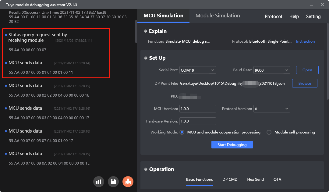
0x03 - Request device status:
0x08(The module must be connected to the mobile app or the gateway over Bluetooth.) - Request MCU version:
0xE8 - Proactive MCU version reporting:
0xE9 - Sending the current time:
0xE1(The module must be connected to the mobile app or the gateway over Bluetooth.)
Send heartbeats
Purpose: Heartbeats are used to detect failures of the MCU or the module.
Scenario: After the module is powered on, it sends heartbeats to the MCU every 3 seconds. If the MCU responds to a heartbeat request, the module will then send 0x01 to get the MCU information. The MCU can determine whether the module works properly according to the heartbeat. If the module does not send heartbeats at regular intervals, the MCU can use the reset pin to reset the module.
- The module sends a heartbeat every 10 seconds in the standard power mode. The heartbeat communication stops in the lower power mode.
- Since the Telink Bluetooth module does not send heartbeats after getting the MCU information, it cannot detect whether the MCU has been restarted after that.
Example:
- The module sends
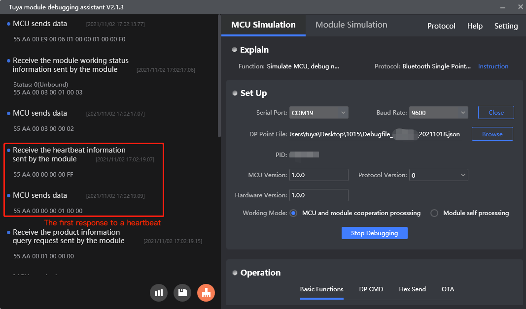
55 AA 00 00 00 00 FF. - The MCU returns
55 AA 00 00 00 01 00 00on the first-time heartbeat communication after a restart. - The MCU returns
55 AA 00 00 00 01 01 01on recurring heartbeat communication.
For more information, see Send heartbeats.
Get MCU information
Purpose: The module requests the product ID (PID) and MCU firmware version.
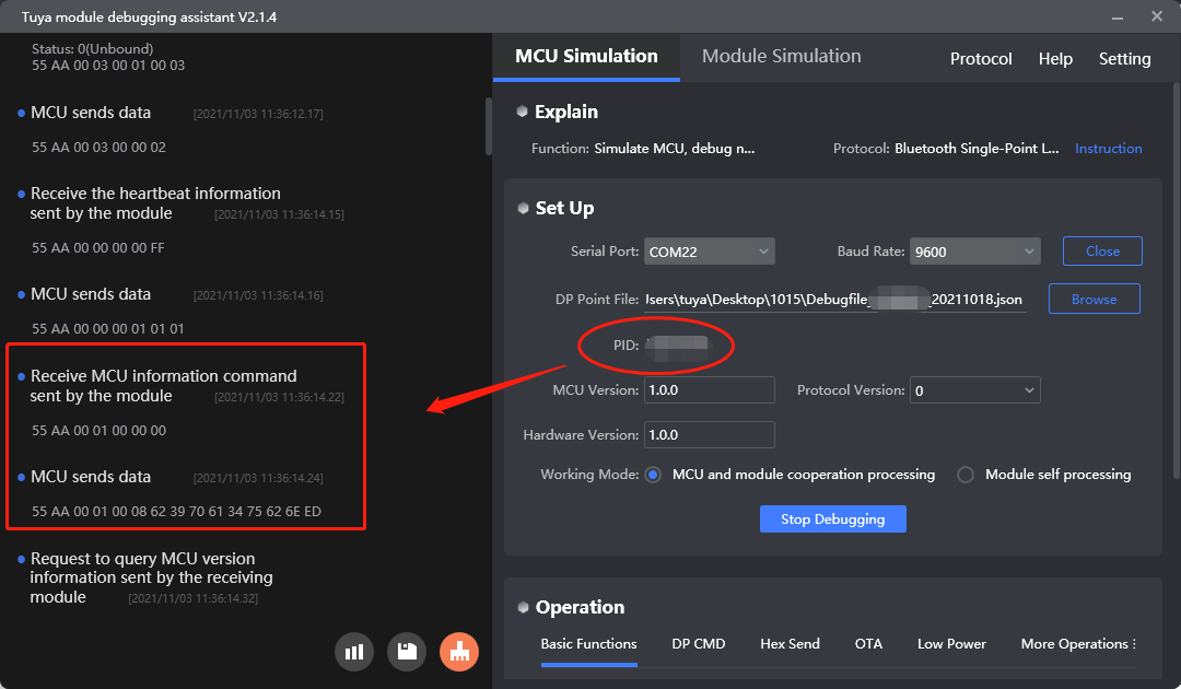
Scenario: After the MCU responds to a heartbeat, the module will request the product information. The MCU returns the PID and its firmware version.
If the MCU returns the wrong information, the module will keep sending the request. Check whether the data content and format are correct. The module does not parse the MCU firmware version so the MCU needs to report its firmware version through 0xE8 or 0xE9.
Example:
-
The module sends
55 AA 00 01 00 00 00. -
The MCU returns
55 AA 00 01 00 0D 6F 30 79 74 64 7A 66 64 31 2E 30 2E 30 2E.
| Field | Description | Bytes | ASCII | Hexadecimal |
|---|---|---|---|---|
| p | PID | 8 | o0ytdzfd | 6F 30 79 74 64 7A 66 64 |
| v | MCU version | 5 | 1.0.0 | 31 2E 30 2E 30 |
For more information, see Get MCU information.
Get the working mode
Purpose: The module requests its working mode.
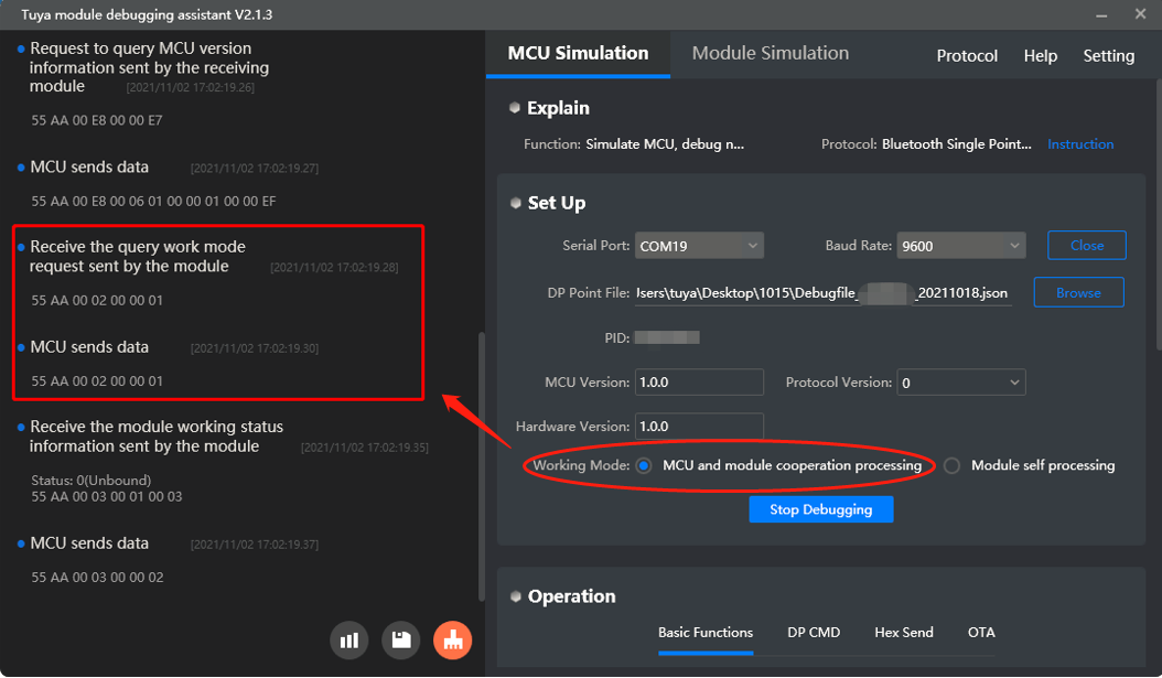
Scenario: After the product information request, the module will send 0x02 to get the working mode. The working mode indicates how the work status of the module is indicated and the way to trigger module reset.
-
The MCU works with the module to process network events.
-
Module reset: The MCU sends a reset command to trigger module reset.
-
Work status indicator: The module sends its current work status to the MCU through serial communication. The MCU controls the LED to indicate status accordingly.
-
-
The module processes network events itself: The Bluetooth module does not support this mode currently.
For more information, see Get working mode.
Send work status
Purpose: The module proactively sends its current work status to the MCU.
Scenario:
- The module will send its current work status to the MCU after responding to the command
0x02. - The module will send its current work status to the MCU if the status changes.
- The module proactively sends its current work status to the MCU after a restart.
Work status:
| State | Description | Things to note |
|---|---|---|
| 0x00 0x01 |
|
The health or sharing devices can be added to the mobile app either in the unbound state or bound but not connected state. |
| 0x02 | Bound and connected | For health or sharing devices, this state indicates that a device is added to the mobile app and connected to the cloud. |
For more information, see Send work status.
Request device status
Purpose: The module requests the current status of all DPs. The MCU reports the status through 0x07.
The module sends device status queries in the following situations:
-
For a bound and connected module, it detects that the MCU is restarted based on the heartbeat communication.
The Telink generic firmware does not support detecting MCU restart.
-
A bound module is reconnected after it goes offline.
For more information, see Request device status.
Get MCU version
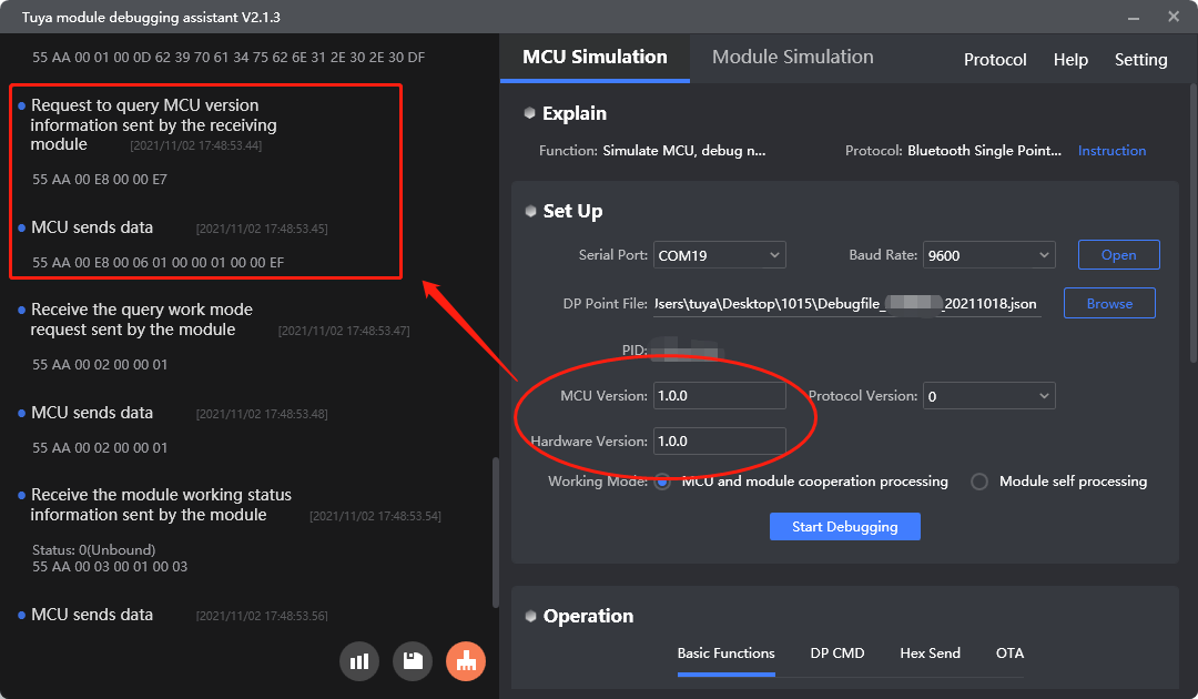
Purpose: The module requests the MCU hardware and firmware version.
Scenario: The module uses this command to get the MCU hardware and firmware version number while it sends 0x01 to get the MCU information.
For more information, see Get MCU version.
Proactively report MCU version
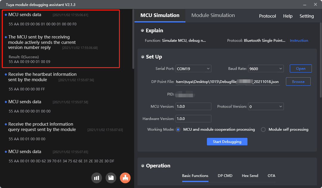
Purpose: The MCU proactively sends its current MCU firmware version to the module.
Scenario: The MCU proactively sends its current firmware version to the module after startup. If the module does not respond to the message, the MCU will send it again.
Example:
-
The MCU sends
55 AA 00 E9 00 06 01 00 00 01 00 00 F0, indicatingSoft_Veris1.0.0andHard_veris1.0.0. -
The module returns
55 AA 00 E9 00 01 00 E9.00indicates the proactive reporting succeeds.
For more information, see Proactive MCU version reporting.
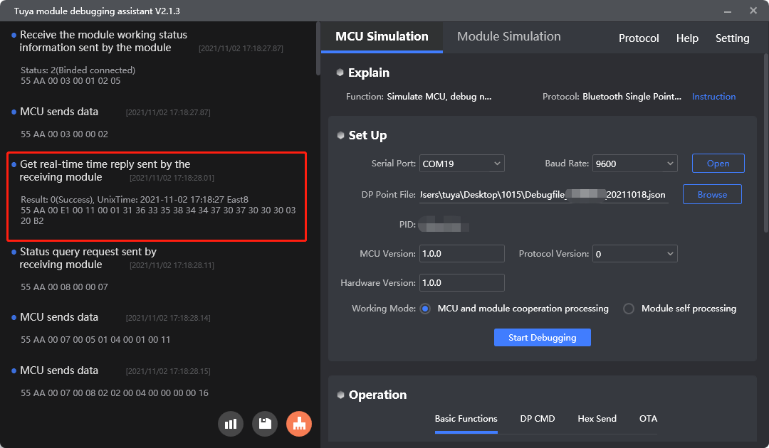
Get the current time
Purpose: The MCU sends this command to get the current time after it selects the required date and time format.
Scenario:
-
After the module is connected to the cloud, it will proactively sync the server time with the MCU in the format of
0x01. -
The MCU proactively sends this command to the module to get the current time.
Date and time format:
Time_Type |
Description |
|---|---|
0x00 |
Format 0: 7-byte date and time value and 2-byte time zone value. The year calculated by 2018+year. |
0x01 |
Format 1: 13-byte Unix time value in milliseconds and 2-byte time zone value. |
0x02 |
Format 2: 7-byte date and time value and 2-byte time zone value. The year calculated by 2000+year. |
For more information, see Get the current time.
Protocol examples
-
Send heartbeats
-
Get MCU information
-
Get the working mode
-
Send work status
-
Request DP status
-
Get MCU version
-
Proactive MCU version reporting
-
Get the current time
MCU SDK sample code
Entry point description
The entry point bt_uart_service() in mcu_api.c is used for the MCU to receive and process serial data sent from the module.
The process is as follows:
-
The MCU calls
bt_uart_service()to verify the format and checksum of the serial data. -
Then, it calls
data_handle()to process the serial data.The MCU must call
bt_uart_service()in the loop body of themainfunction, without any conditional statements./***************************************************************************** Function name: bt_uart_service Function description: bt serial port processing service Input parameters: none Return parameter: none Instructions: call this function in the while loop of the MCU main function ************************************************************************* void bt_uart_service(void) { static unsigned short rx_in = 0; unsigned short offset = 0; unsigned short rx_value_len = 0; //Data frame length if((rx_in < sizeof(bt_uart_rx_buf)) && get_queue_total_data() > 0) { if(mcu_common_uart_data_unpack(Queue_Read_Byte())) { if((bt_uart_rx_buf[0]==0x55)&&(bt_uart_rx_buf[1]==0xAA)&&(bt_uart_rx_buf[2]==0x00)) { data_handle(0); rx_value_len = bt_uart_rx_buf[LENGTH_HIGH] * 0x100 + bt_uart_rx_buf[LENGTH_LOW] + PROTOCOL_HEAD; } else if((bt_uart_rx_buf[0]==0x66)&&(bt_uart_rx_buf[1]==0xAA)&&(bt_uart_rx_buf[2]==0x00)) { rx_value_len = bt_uart_rx_buf[LENGTH_HIGH] * 0x100 + bt_uart_rx_buf[LENGTH_LOW]; factory_test_handler(bt_uart_rx_buf[FRAME_TYPE],&bt_uart_rx_buf[DATA_START],rx_value_len); } my_memset(bt_uart_rx_buf_temp,0,3); my_memset(bt_uart_rx_buf,0,sizeof(bt_uart_rx_buf)); UART_RX_Count = 0; current_uart_rev_state_type = MCU_UART_REV_STATE_FOUND_NULL; uart_data_len = 0; } } } }
Heartbeat connection
heat_beat_check() in system.c is used for the MCU to respond to heartbeats.
The process is as follows:
-
The serial data handler
data_handle()receives a heartbeat. -
The MCU calls
heat_beat_check()to respond to a heartbeat. It returns0x00on its first response to a heartbeat and returns0x01on later heartbeat checks. -
This feature is implemented in the SDK.
/*****************************************************************************
Function name: data_handle
Function description: data frame processing
Input parameter:
	Offset: Data start bit
Return parameter: none
*****************************************************************************/
void data_handle(unsigned short offset)
{
	......
	case HEAT_BEAT_CMD:                                     // Send a heartbeat.
			heat_beat_check();                              // Respond to a heartbeat.
		break;
		......
}
/***************************************************************************** Function name: heat_beat_check Function description: Heartbeat packet detection Input parameters: none Return parameter: none *****************************************************************************/ static void heat_beat_check(void) { unsigned char length = 0; static unsigned char mcu_reset_state = FALSE; if(FALSE == mcu_reset_state) { length = set_bt_uart_byte(length,FALSE); mcu_reset_state = TRUE; } else { length = set_bt_uart_byte(length,TRUE); } bt_uart_write_frame(HEAT_BEAT_CMD, length); }data_handle()insystem.cis used to receive and process data from the module.bt_uart_write_frame()insystem.cis used for the MCU to send serial data to the module.
Return product information
product_info_update() in system.c is used for the MCU to return product information.
The process is as follows:
-
The serial data handler
data_handle()receives a product information request. -
Write the PID and MCU firmware version number to the macro.
-
The MCU calls
product_info_update()to report product information. -
This feature is implemented in the SDK.
You must enable or modify macros to specify the product information such as PID and MCU version number.
#define PRODUCT_KEY "o0ytdzfd"    // The unique identifier of the product you have created on the Tuya Developer Platform.
#define MCU_VER "1.0.0"
void data_handle(unsigned short offset) { ...... case PRODUCT_INFO_CMD: // Request product information. product_info_update(); break; ...... }/***************************************************************************** Function name: product_info_update Function description: upload product information Input parameters: none Return parameter: none *****************************************************************************/ static void product_info_update(void) { unsigned char length = 0; length = set_bt_uart_buffer(length,(unsigned char *)PRODUCT_KEY,my_strlen((unsigned char *)PRODUCT_KEY)); length = set_bt_uart_buffer(length,(unsigned char *)MCU_VER,my_strlen((unsigned char *)MCU_VER)); bt_uart_write_frame(PRODUCT_INFO_CMD, length); }
Working mode of the module
get_mcu_bt_mode(void) in system.c is used for the MCU to configure the working mode of the module.
The process is as follows:
-
The serial data handler
data_handle()receives a working mode request. -
Call
get_mcu_bt_mode()to report the working mode to the module. -
This feature is implemented in the SDK.
You can enable or disable
BT_CONTROL_SELF_MODEto set the working mode. If you use the module self-processing mode, you need to set the reset pin and network status LED pin. Currently, the Bluetooth module supports the collaboration mode only.//#define BT_CONTROL_SELF_MODE / / bt self-processing button and LED indicator; if it is MCU external button / LED indicator, please turn off the macro #ifdef BT_CONTROL_SELF_MODE // Module self-processing #define BT_STATE_KEY 14 //Bt module status indication button, please set according to the actual GPIO pin #define BT_RESERT_KEY 0 //Bt module reset button, please set according to the actual GPIO pin #endifvoid data_handle(unsigned short offset) { ...... case WORK_MODE_CMD: // Request module working mode set by MCU get_mcu_bt_mode(); break; ...... }/***************************************************************************** Function name: get_mcu_bt_mode Function description: request the working mode of MCU and Bluetooth module Input parameters: none Return parameter: none *****************************************************************************/ static void get_mcu_bt_mode(void) { unsigned char length = 0; #ifdef BT_CONTROL_SELF_MODE //Module self-processing length = set_bt_uart_byte(length, BT_STATE_KEY); length = set_bt_uart_byte(length, BT_RESERT_KEY); #else //No need to process data #endif bt_uart_write_frame(WORK_MODE_CMD, length); }
Send work status
The MCU receives the work status of the module from data_handle().
The process is as follows:
-
If the module works with the MCU to process network events,
data_handle()is used for the MCU to receive the work status of the module and assign the received value tobt_work_state. -
If the work status is
0x00or0x01, the MCU callsmcu_ota_init_disconnect()to configure OTA update initialization. -
This feature is implemented in the SDK.
void data_handle(unsigned short offset)
{
	......
	#ifndef BT_CONTROL_SELF_MODE
	case BT_STATE_CMD:                                  //bt work state
	bt_work_state = bt_uart_rx_buf[offset + DATA_START];
	if(bt_work_state==0x01||bt_work_state==0x00)
	{
		mcu_ota_init_disconnect();
	}
	bt_uart_write_frame(BT_STATE_CMD,0);
	break;
	......
}
Report status of all DPs
all_data_update(void) in protocol.c is used for the MCU to report the status of all DPs.
The process is as follows:
-
The serial data handler
data_handle()receives a device status request. -
The MCU calls
all_data_update()to report the status of all DPs to the module for sync with the mobile app.The MCU should call the correct function in
all_data_update()according to the data type of a DP. For example, it callsmcu_dp_bool_update()to report the status of a Boolean DP, and the parameters are the corresponding DP ID and DP status data.mcu_dp_value_update()is for DPs of value type,mcu_dp_enum_update()is for DPs of enum type, and so on.The specific function is intended to be implemented by you.
void data_handle(unsigned short offset)
{
	......
	case STATE_QUERY_CMD:                                 // Status request
			all_data_update();
		break;
		......
}
/***************************************************************************** Function name: all_data_update Function description: upload all dp information of the system to achieve data synchronization between App and MCU Input parameters: none Return parameter: none Instructions for use: this function needs to be called internally in SDK MCU must implement the data reporting function within this function, including reporting only and downloadable hairstyle data. *****************************************************************************/ void all_data_update(void) { #error "Please process all DP data here and delete the row when the processing is complete" // This code is automatically generated for the platform. Please modify each function according to the actual data mcu_dp_value_update(DPID_TARGET_WATER,water intake goal); // Report value data mcu_dp_value_update(DPID_WATER_TEMP,current temperature); // Report value data mcu_dp_value_update(DPID_WATER_INTAKE,current intake amount); // Report value data mcu_dp_value_update(DPID_WATER_TIMES,current drinking times); // Report value data mcu_dp_value_update(DPID_BATTERY_PERCENTAGE,current battery level); // Report value data mcu_dp_value_update(DPID_WATER_REMIND,hydration reminder); // Report value data mcu_dp_fault_update(DPID_FAULT,current fault alert); // Report fault data }
Proactive MCU version reporting
bt_send_mcu_ver(void) in system.c is used for the MCU to proactively send its version number to the module after power-on.
The process is as follows:
-
Enable
TUYA_BCI_UART_COMMON_MCU_SEND_VERSIONand specify the MCU hardware and software version number to turn on the command0xE9. -
After power-on, the MCU calls this function to proactively send its current firmware version to the module.
The module processes data in
data_handle()on receiving the version number. The specific function is intended to be implemented by you.#define MCU_APP_VER_NUM 0x010000 //User's software version, used for MCU firmware upgrade, MCU upgrade version needs to be modified eg.1.0.0 #define MCU_HARD_VER_NUM 0x010000 //The hardware version of the user is currently of no practical use#ifdef TUYA_BCI_UART_COMMON_MCU_SEND_VERSION /***************************************************************************** Function name: bt_send_mcu_ver Function description: send the MCU version number to the module actively, mainly in order that the module can obtain the MCU version information in a more timely manner. Return parameter: none Instructions: MCU can be called once after the initialization of the serial port. *****************************************************************************/ void bt_send_mcu_ver(void) { unsigned short length = 0; length = set_bt_uart_buffer(length,(unsigned char *)MCU_APP_VER_NUM,3); length = set_bt_uart_buffer(length,(unsigned char *)MCU_HARD_VER_NUM,3); bt_uart_write_frame(TUYA_BCI_UART_COMMON_MCU_SEND_VERSION,length); } #endif
Get the current time
bt_send_time_sync_req() in protocol.c is used for the MCU to get the current time.
The process is as follows:
-
The MCU calls
bt_send_time_sync_req()to get the current time. -
Then, it receives the time data from
data_handle()if the data format is correct. -
bt_time_sync_result()can determine whether to process the received time data.The specific function is intended to be implemented by you.
/*****************************************************************************
Function name: bt_send_time_sync_req
Function description: Send time synchronization request to module
Input parameter: sync_time_type
0x00- Gets 7 bytes of time time type +2
Byte time zone information
0x01- Gets 13 bytes of MS level Unix time
+ 2-byte time zone information
0x02-get 7 byte time type + 2 Byte time zone information
Return parameter: none
*****************************************************************************/
void bt_send_time_sync_req(unsigned char sync_time_type)
{
	unsigned short length = 0;
	length = set_bt_uart_byte(length,sync_time_type);
	bt_uart_write_frame(TUYA_BCI_UART_COMMON_SEND_TIME_SYNC_TYPE,length);
}
void data_handle(unsigned short offset) { ...... case TUYA_BCI_UART_COMMON_SEND_TIME_SYNC_TYPE: ret = bt_uart_rx_buf[offset + DATA_START]; if(ret==0)//Get time succeeded { if(bt_uart_rx_buf[offset + DATA_START+1]==0x00)//Time format 0 :Get 7 bytes of time and time type + 2 bytes of time zone information { bt_time.nYear = bt_uart_rx_buf[offset + DATA_START+2] + 2018; bt_time.nMonth = bt_uart_rx_buf[offset + DATA_START+3]; bt_time.nDay = bt_uart_rx_buf[offset + DATA_START+4]; bt_time.nHour = bt_uart_rx_buf[offset + DATA_START+5]; bt_time.nMin = bt_uart_rx_buf[offset + DATA_START+6]; bt_time.nSec = bt_uart_rx_buf[offset + DATA_START+7]; bt_time.DayIndex = bt_uart_rx_buf[offset + DATA_START+8]; time_zone_100 = ((unsigned short)bt_uart_rx_buf[offset + DATA_START+9]<<8)+bt_uart_rx_buf[offset + DATA_START+10]; } else if(bt_uart_rx_buf[offset + DATA_START+1]==0x01)//Time format 1: Get 13 bytes of ms-level unix time + 2 bytes of time zone information { my_memcpy(current_timems_string,&bt_uart_rx_buf[offset + DATA_START+2],13); time_stamp_ms = my_atoll(current_timems_string); time_zone_100 = ((unsigned short)bt_uart_rx_buf[offset + DATA_START+15]<8)+bt_uart_rx_buf[offset + DATA_START+16]; } else if(bt_uart_rx_buf[offset + DATA_START+1]==0x02)//Time format 2: Get 7 bytes of time and time type + 2 bytes of time zone information { bt_time.nYear = bt_uart_rx_buf[offset + DATA_START+2] + 2000; bt_time.nMonth = bt_uart_rx_buf[offset + DATA_START+3]; bt_time.nDay = bt_uart_rx_buf[offset + DATA_START+4]; bt_time.nHour = bt_uart_rx_buf[offset + DATA_START+5]; bt_time.nMin = bt_uart_rx_buf[offset + DATA_START+6]; bt_time.nSec = bt_uart_rx_buf[offset + DATA_START+7]; bt_time.DayIndex = bt_uart_rx_buf[offset + DATA_START+8]; time_zone_100 = ((unsigned short)bt_uart_rx_buf[offset + DATA_START+9]<<8)+bt_uart_rx_buf[offset + DATA_START+10]; } bt_time_sync_result(0,bt_uart_rx_buf[offset + DATA_START+1],bt_time,time_zone_100,time_stamp_ms); } else//Failed to get time { bt_time_sync_result(1,bt_uart_rx_buf[offset + DATA_START+1],bt_time,time_zone_100,time_stamp_ms); } break; ...... }/***************************************************************************** Function name: bt_time_sync_result Function description: send the result of time synchronization to the module Input parameters: result synchronization result 0 successful, other failed sync_time_type :time format Bt_time: Custom time (valid if time format 0 or 1) Time_zone_100: time zone Time_stamp_ms: timestamp (valid if it is in time format 1) Return parameter: none Instructions: MCU needs to improve the function on its own. *****************************************************************************/ void bt_time_sync_result(unsigned char result,unsigned char sync_time_type,bt_time_struct_data_t bt_time,unsigned short time_zone_100,long long time_stamp_ms) { #error "Please improve the function by yourself and delete the line after completion" if(result == 0x00) { // synchronization time is successful if(sync_time_type==0x00||sync_time_type==0x02) { // populate the data of custom time format in bt_time into the MCU clock system //time_zone_100 } else if(sync_time_type==0x01) { // populate the timestamp in time_stamp_ms into the MCU clock system //time_zone_100 } } else { // synchronization time failed } }
Device pairing
The MCU sends a reset command to the module to enable it to enter pairing mode. The module will communicate and pair with the mobile app or the gateway so that it can be connected to the cloud.
Feature description
This section describes how to enter pairing mode. For more information about pairing with the Tuya app, see User Guide.
How it works: After the mobile app or the Bluetooth gateway receives the product information broadcast by the module, it will connect to the module over Bluetooth and exchange information. If the authentication succeeds, the module is paired. Bluetooth pairing provides fast device discovery and a reliable pairing process. As long as the module is in the pairing mode, it will keep broadcasting.
Scenarios
To pair with a mobile app, the module must enter pairing mode first.
For more information, see Bluetooth Serial Communication Protocol.
Scenario:
The MCU sends a reset command to enable the module to enter pairing mode. Generally, products are designed with a physical reset button, so that pressing the reset button can trigger a reset command sent to the module.
If you have edited the data point (DP) on the platform, remove the device and pair again.
If a bound module is physically reset, the device will not be removed from the mobile app but its status will become offline. This is because the Bluetooth module is connected to the cloud through a gateway, such a hardware reset is not synced with the cloud. If this module is paired after a reset, the current device icon will be removed from the mobile app.
Commands
The MCU sends a reset command to enable the module to enter pairing mode.
- Reset the module:
0x04 - Reset the module (new):
0x05 - Unbind the module:
0x09
The above reset commands are used in different scenarios.
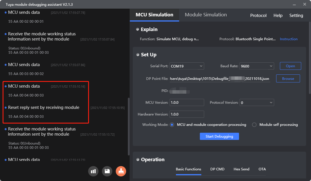
Reset the module
Purpose: After the MCU sends this command, the Bluetooth module will be disconnected and unbound. Its virtual ID and cache data will be cleared. The device data will be erased from the cloud after the virtual ID is removed.
Scenario: The MCU sends 0x04 to enable the module to enter the pairing mode.
For Bluetooth modules using Telink chips, resetting the module with the command 0x04 will not clear the virtual ID. If you want to reset the Telink-based module and clear its virtual ID at the same time, use the command 0x05.
For more information, see Reset the module.
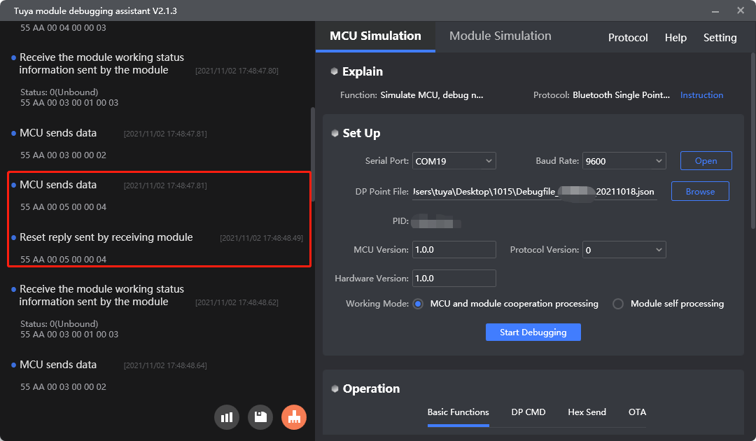
Reset the module (new)
Purpose: After the MCU sends this command, the Bluetooth module will be disconnected and unbound. Its virtual ID and cache data will be cleared. The device data will be erased from the cloud after the virtual ID is removed. This command works the same way as the 0x04. The only difference is that using this command to reset a Telink-based module will clear its virtual ID.
Scenario: The MCU sends 0x05 to enable the module to enter the pairing mode.
Only TLSR825x generic firmware v7.22 and later versions support the command 0x05.
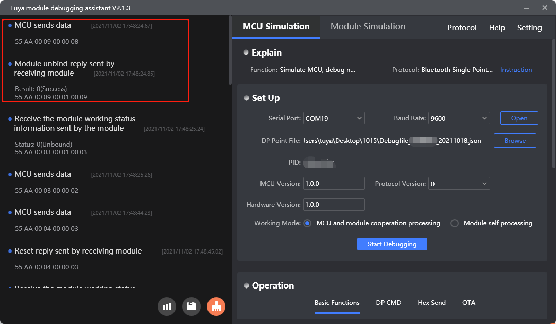
Unbind the module
Purpose: After the MCU sends this command, the Bluetooth module will be disconnected and unbound. Its virtual ID and cache data will not be cleared. The user profile can be loaded and used after the module is connected to the cloud again.
Scenario: The MCU sends 0x09 to enable the module to enter the pairing mode.
Health or sharing devices do not support the command 0x09.
For more information, see Unbind modules.
Protocol examples
-
Reset the module
-
Reset the module (new)
-
Unbind the module
MCU SDK sample code
Reset the module
mcu_reset_bt() in mcu_api.c is used to send a network reset command to the module.
The process is as follows:
In data_handle(), if the MCU receives the module’s response to the reset command, it activates reset_bt_flag. The value of reset_bt_flag returned by mcu_get_reset_bt_flag() determines whether the reset succeeds.
You can define when to initiate pairing so that the MCU will proactively call mcu_reset_bt().
/*****************************************************************************
Function name: mcu_reset_bt
Function description: MCU actively resets bt working mode
Input parameters: none
Return parameter: none
Instructions for use: 1:MCU is called actively, and the mcu_get_reset_bt_flag () function is used to obtain whether the reset bt is successful or not.
		   2: if it is in module self-processing mode, MCU does not need to call this function
*****************************************************************************/
void mcu_reset_bt(void)
{
  reset_bt_flag = RESET_BT_ERROR;

  bt_uart_write_frame(BT_RESET_CMD, 0);
}
void data_handle(unsigned short offset)
{
	……
    case BT_RESET_CMD:                         //Reset BT (BT returns success)
    reset_bt_flag = RESET_BT_SUCCESS;
    	break;
        ……
}
/*****************************************************************************
Function name: mcu_get_reset_bt_flag
Function description: MCU acquires reset Bluetooth success flag
Input parameters: none
Return parameter: RESET_BT_ERROR:failed/RESET_BT_SUCCESS:success
Instructions for use: 1:MCU call this function after calling mcu_reset_bt () actively to get the reset state
		   2: if it is in module self-processing mode, MCU does not need to call this function
*****************************************************************************/
unsigned char mcu_get_reset_bt_flag(void)
{
  return reset_bt_flag;
}
Unbind the module
bt_unbound_req() in protocol.c is used for the MCU to send an unbinding command to the module.
Scenarios:
The MCU initiates the command to unbind a module from the mobile app or gateway. You can design a hardware button as the unbinding trigger. When the MCU detects a button-press event, it will call the bt_unbound_req() to initiate the unbinding operation.
The process is as follows:
-
Enable
TUYA_BCI_UART_COMMON_UNBOUND_REQto turn on the unbinding feature. -
After power-on, the MCU calls this function to send
0x09to the module. -
The module receives and processes the unbinding command from the
data_handle(). The specific processing function is intended to be implemented by you.The specific function is intended to be implemented by you.
#ifdef TUYA_BCI_UART_COMMON_UNBOUND_REQ
/*****************************************************************************
Function name: bt_unbound_req
Function description: Send the unbind request to the module, and the module will unbind the Bluetooth connection after receiving the instruction
Input parameters: None
Return parameter: none
Instructions: The MCU calls for active untying
*****************************************************************************/
void bt_unbound_req(void)
{
	bt_uart_write_frame(TUYA_BCI_UART_COMMON_UNBOUND_REQ,0);
}
#endif
Data transfer
Feature description
The remote control works based on the two-way communication between the device and the cloud. The device reports status to the cloud and the cloud sends control commands to the device.
This section describes how the two-way data transfer works.
During debugging, if you modify the DP of a product on the Tuya Developer Platform, you must remove this product from the mobile app and bind it again. Otherwise, errors might occur.
Principle:
-
The MCU reports the DP whose status is updated, except for the response to the command
0x08. -
Try to avoid frequent status reporting. Otherwise, unknown errors might occur, such as devices getting offline or data loss. Reporting frequency of less than one frame per second is recommended.
Scenarios
Bi-directional communication between the cloud or the mobile app and devices.
-
Send data: The mobile app sends data to the module. The module sends it to the MCU through serial communication.
-
Report data: The MCU sends data to the module through serial communication, and then the module reports it to the cloud and the mobile app.
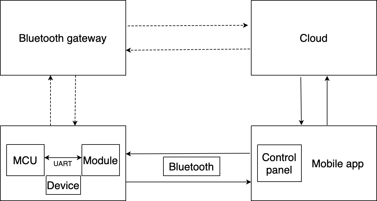
The above communication is achieved by direct connection to the mobile app over Bluetooth. The other way is the connection to the mobile app through a Bluetooth gateway, which can enable the remote control.
- Communication with Bluetooth gateway: After the Bluetooth device is connected to the gateway, users can control this device from anywhere. The mobile app sends a control command to the gateway through the cloud, and then the gateway forwards data to the device. For the device-to-cloud messages, the device sends data to the gateway, and then the gateway forwards data to the mobile app through the cloud.
- Device control over Bluetooth: A device is bound with the mobile app. It can directly communicate with the mobile app over Bluetooth.
Commands
The commands used in the bidirectional communication.
- Send commands:
0x06 - Report status:
0x07 - Report record-type data:
0xE0
Send commands
When a device is connected with the mobile app, the app can send control commands to the module. The module sends the received command to the MCU through serial communication. The MCU processes the command.
-
It calls
0x07to respond to the received command. For example, the mobile app sends a command to set the hydration reminder to 60 minutes.-
The module sends
55 AA 00 06 00 08 06 02 00 04 00 00 00 3C 55. -
The MCU returns
55 AA 00 07 00 08 06 02 00 04 00 00 00 3C 56. -
The module returns
55 AA 00 07 00 01 00 07.The MCU must respond with the data of the same DP.
-
-
The MCU executes the control command. For example, the MCU changes the hydration reminder to 60 minutes.
For more information, see Send commands.
Report status asynchronously
Scenario:
- When the MCU receives the DP status request (
0x08), it sends the status of all DPs to the module through0x07. - After the MCU executes the command received from the module, it reports the changed DP status to the module.
- When the MCU proactively detects status changes of DPs, it reports the changed DP status to the module through
0x07.
Things to note
-
Data length: indicates the length of DP data, not the length of a complete frame of data. The data length depends on the DP data type and the number of DPs. If needed, values can be padded on the left with zeros to meet the length requirement. For more information, see Data point format.
-
Bitmap data: supports reporting multiple faults at the same time. Each bit represents an alert.
1indicates a fault occurs and0indicates no fault occurs. The bitmap data can be one, two, or four bytes. Data greater than one byte is transmitted in big-endian format. For example, if the MCU sends55 aa 03 07 00 06 0d 05 00 02 00 09 2C, it indicates that the faults ofbit0andbit3are reported. If you want to configure alert messages, see Configure Push Notification. -
String data: the denotation of the string data must match the specifications of the control panel on the mobile app. The string data must be converted into hexadecimal values to report. For example, if the MCU sends
55 AA 03 07 00 08 6E 03 00 04 74 65 73 74 46,74 65 73 74denotes the charactertest. -
Grouped status reporting: indicates the module reports status data of multiple DPs to improve the efficiency of data transfer. For example, the MCU sends
55 aa 03 07 00 00 03 02 00 04 00 00 00 19 04 04 00 01 00 {checksum}, it indicates the current temperature is 25°C and the operation mode is Smart.
For more information, see Report status.
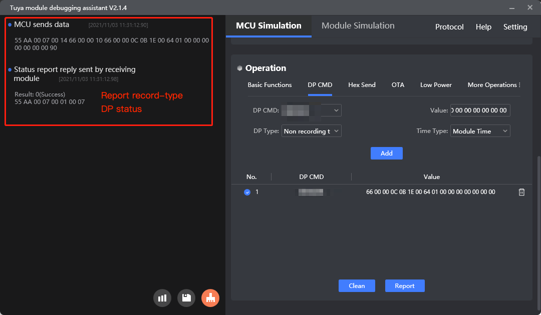
Report record-type data
Purpose: If the module is offline when the MCU reports data, it will save the data to its flash memory and send the stranded data after going online. After the last piece of stranded data is sent to the cloud, the module will delete the cache.
Scenario: Use this command to report important data so as to retain the data for reporting in case of network downtime.
The volume of cache data varies depending on the chipset platforms.
| Chipset platform | DP data |
|---|---|
| nRF52832/BK3431Q | Retain up to 80 records. No more than 200 bytes of each record. |
| BK3432 | Retain up to 32 records. No more than 32 bytes of each record. |
Time accuracy: The time drift of the module’s internal clock is less than one minute in 24 hours. The module will sync its clock with the server time each time it is connected to the cloud. If you require highly accurate time, you can report data using the MCU’s timestamp.
For more information, see Report record-type data.
Protocol examples
-
Send data: The data marked with a red rectangle indicates the module sends a command to the MCU.
-
Report data: The data marked with a green rectangle indicates the MCU reports data to the module, occurring when it reports the changed DP status after executing a command, proactively reports status, or responds to the command
0x08.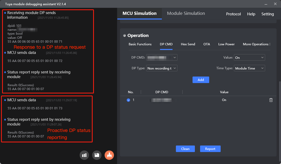
MCU SDK sample code
Send commands
data_point_handle() in system.c is used for the MCU to process commands from the module.
The process is as follows:
-
The serial data handler
data_handle()receives the control command sent from the module. -
The MCU calls
data_point_handle()to get the data unit and verify the data format. -
data_point_handle()callsdp_download_handle()to process the received command.dp_download_handle()will call the correct function according to the DP ID to execute the command and return the updated DP status to the module.The specific function is intended to be implemented by you.
void data_handle(unsigned short offset)
{
	......
	case DATA_QUERT_CMD:                                  //dp data handled
	total_len = bt_uart_rx_buf[offset + LENGTH_HIGH] * 0x100;
	total_len += bt_uart_rx_buf[offset + LENGTH_LOW];

	for(i = 0;i < total_len;)
	{
	dp_len = bt_uart_rx_buf[offset + DATA_START + i + 2] * 0x100;
	dp_len += bt_uart_rx_buf[offset + DATA_START + i + 3];
	//
	ret = data_point_handle((unsigned char *)bt_uart_rx_buf + offset + DATA_START + i);
	if(SUCCESS == ret)
	{
		//Success tips
	}
	else
	{
		//Error message
	}
	i += (dp_len + 4);
	}
	break;
	......
}
/***************************************************************************** Function name: data_point_handle Function description: send data processing Input parameter: value: the pointer of the data source issued Return parameter: ret: return data processing result *****************************************************************************/ static unsigned char data_point_handle(const unsigned char value[]) { unsigned char dp_id,index; unsigned char dp_type; unsigned char ret; unsigned short dp_len; dp_id = value[0]; dp_type = value[1]; dp_len = value[2] * 0x100; dp_len += value[3]; index = get_dowmload_dpid_index(dp_id); if(dp_type != download_cmd[index].dp_type) { //Error message return FALSE; } else { ret = dp_download_handle(dp_id,value + 4,dp_len); } return ret; }
Report status
According to data types, the asynchronous data reporting functions are classified into:
mcu_dp_raw_update()mcu_dp_bool_update()mcu_dp_value_update()mcu_dp_string_update()mcu_dp_enum_update()mcu_dp_fault_update()
These functions defined in mcu_api.c are used for the MCU to report DP status. For example, if DP 1 is Boolean type, mcu_dp_bool_update() is used for the MCU to report data.
The specific function is intended to be implemented by you.
/*****************************************************************************
Function name: mcu_dp_bool_update
Function description: Bool dp data upload
Input parameter: dpid:id number
           value:
Return parameter: none
*****************************************************************************/
unsigned char mcu_dp_bool_update(unsigned char dpid,unsigned char value)
{
  unsigned short length = 0;

  if(stop_update_flag == ENABLE)
    return SUCCESS;
  length = set_bt_uart_byte(length,dpid);
  length = set_bt_uart_byte(length,DP_TYPE_BOOL);
  //
  length = set_bt_uart_byte(length,0);
  length = set_bt_uart_byte(length,1);
  //
  if(value == FALSE)
  {
    length = set_bt_uart_byte(length,FALSE);
  }
  else
  {
    length = set_bt_uart_byte(length,1);
  }
  bt_uart_write_frame(STATE_UPLOAD_CMD,length);
  return SUCCESS;
}
Report record-type data
bt_send_recordable_dp_data() in protocol.c is used for the MCU to report record-type data.
The process is as follows:
-
Enable
TUYA_BCI_UART_COMMON_SEND_STORAGE_TYPEto turn on reporting record-type data. -
The MCU calls
bt_send_recordable_dp_data()to report record-type data. -
The MCU gets the reporting result from
data_handle()and callsbt_send_recordable_dp_data_resultto proceed with the next operation.The specific function is intended to be implemented by you.
/*****************************************************************************
Function name: bt_send_recordable_DP_data
Function description: report the recorded data
Input parameters: Type-1: Bluetooth module built-in time report -2: original data only report, no time -3: MCU built-in time report
		Dpid: former datapoint serial number
		Dptype: Corresponds to a datapoint specific data type on the open platform
		value:
		len:
Return parameter: none
Instructions: the MCU needs to improve the function itself
	It is recommended to use the cache queue. All data to be sent to the module should be put into the MCU cache queue, and the next data should be reported after one has been reported successfully. The recorded data should ensure that each data has been reported successfully
*****************************************************************************/
void bt_send_recordable_dp_data(unsigned char snedType,unsigned char dpid,unsigned char dpType, unsigned char value[],unsigned short len)
{
	#error "Please improve the function by yourself and delete the line after completion"
	if(snedType==0x01)//Format 1, Bluetooth module self-report time
	{

	}
	else if(snedType==0x02)//Format 2, report only the original data, no time (Note: Telink docking platform does not support this format)
	{

	}
	else if(snedType==0x03)//Format 3, MCU own time report
	{

	}
}
void data_handle(unsigned short offset) { ...... #ifdef TUYA_BCI_UART_COMMON_SEND_STORAGE_TYPE case TUYA_BCI_UART_COMMON_SEND_STORAGE_TYPE: bt_send_recordable_dp_data_result(bt_uart_rx_buf[offset + DATA_START]); break; #endif ...... }/***************************************************************************** Function name: bt_send_recordable_dp_data_result Function description: report the recorded data Input parameter :result: 0 storage success, 1 storage failure Return parameter: none Instructions: the MCU needs to improve the function itself *****************************************************************************/ void bt_send_recordable_dp_data_result(unsigned char result) { #error "Please improve the function by yourself and delete the line after completion" }
Next steps
After you implement the basic features, you can proceed with extended features as needed.
Is this page helpful?
YesFeedbackIs this page helpful?
YesFeedback


