Acoustic Structural Design Specification
This topic describes the acoustic structural design specifications for Tuya’s voice-enabled products.
Purpose
Specify the requirements of acoustic structural design.
Application scope
This document applies to the acoustic structural design for Tuya’s voice-enabled products.
Method and requirement
Structural design
Design of microphone pickup chamber
-
The microphones are distributed independently from each other, and each microphone has a unique sound inlet.
-
Human voice can reach each microphone without masking. This ensures that the direct sound (non-reflected sound) of the sound source has an equal chance of reaching each microphone.
-
Whenever possible, build the microphone seal and the pickup channel with a separate one-piece component, instead of using multiple assemblies. This is because an error chain in production will lead to a decrease in sealing consistency.
-
Ring 6-mic and 4-mic: All sound inlets are located on the same plane. The angle between this plane and the horizontal plane should be within the range of ±10°. The best angle is 0 degrees, that is, they are placed horizontally.
Linear 4-mic and dual-mic: All sound inlets are located in the same straight line, and can be oriented at any angle between upward and forward (toward the speaker).
Single mic: The sound inlet can be oriented at any angle between upward and forward (toward the speaker). -
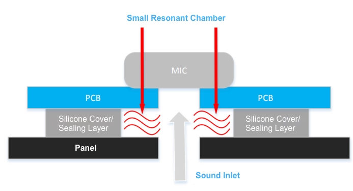
Avoid a resonant chamber that is small at both ends and large in the center. Otherwise, it will interfere with the front-end signal processing.
Single-hole microphone
Design standard:
A microphone consists of the pickup channel, dust filter, sealing layer, PCB opening, and internal sound chamber. The overall frequency of each microphone is 100 Hz to 8 kHz. The frequency response fluctuation is within ±1.5 dB. That is to say, the difference between the maximum value and minimum value is < 3 dB).
Bottom port MEMS microphone
Recommended design:
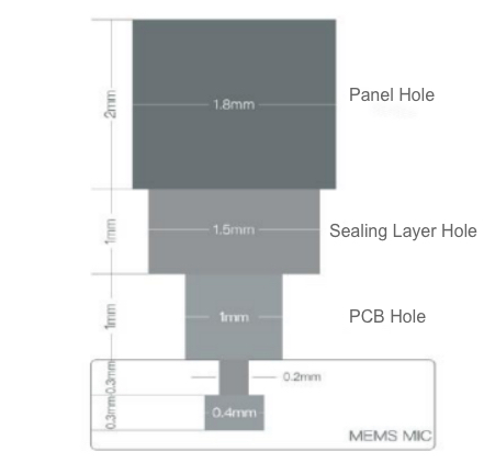
- Panel hole diameter ≥ Sealing layer hole diameter ≥ PCB hole diameter ≥ Sound inlet hole diameter.
- The total thickness of the panel, sealing layer, and PCB does not exceed 5 mm. The smaller the total thickness, the better the performance.
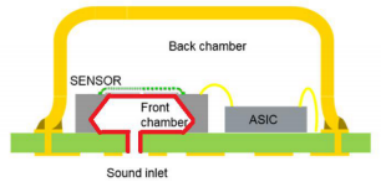
The following figure shows the internal structure of the bottom port MEMS microphone.
Top port MEMS microphone
Recommended design:
- Panel hole diameter ≥ Sealing layer hole diameter ≥ Sound inlet hole diameter.
- The total thickness of the panel and sealing layer does not exceed 5 mm. The smaller the total thickness, the better the performance.
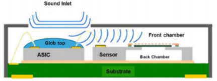
The following figure shows the internal structure of the top port MEMS microphone.
Taking the bottom port MEMS microphone as an example, the single-hole pickup channel looks like this:
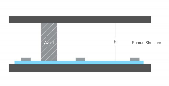
Free-field microphone
All microphones are located in the same open space. Their outer surface is fully acoustically transparent, without a reflection area. The sound pickup hole design is not required, and it can be exposed. We recommend that the porosity of the surrounding plastic or metal porous structure should be not less than 45% and the thickness should not exceed 2 mm. The open space is at least 3 cm high, free from obstacles such as support columns.
Evaluation of design drawing
The following documents need to be submitted for design drawing evaluation:
- The speaker and microphone specifications.
- A 3D drawing of the product in STP format is required to include the pickup chamber, speaker chamber, and other structures that may affect the acoustics. If the speaker uses an external magnet, the passive glob top is made of a non-magnetic material.
Sound-proof and shock-absorbing design
- Take an internal sound-proof measure between the microphone and speaker. Therefore, the speaker sound can be prevented from being directly transmitted to the microphone. Generally, foam and silica gel are used for sound insulation and shock absorption. The foam softness depends on the actual structure. Typically, the foam shall be as soft as possible.
- The microphone should be kept away from interference such as exhaust fans or vibration such as horn vibration and structural vibration.
- The microphone is sealed with a silicone cover and a solid surface to reduce the casing vibration and sound transmission.
For electret microphones, microphone protection should be considered in the structural design and production process to avoid consistency loss due to extrusion.
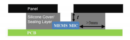
Bottom port MEMS microphone
- A silicone sealing layer is added between the panel and the PCB to prevent a gap or cavity. The total thickness of the panel, sealing layer, and PCB does not exceed 5 mm.
- The MEMS microphone shall be wrapped with silica gel that is at least 3 mm thick.
The following figure shows the sound-proof and shock-absorbing design of a bottom port MEMS microphone.
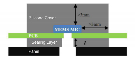
Top port MEMS microphone
- The MEMS microphone is wrapped with silica gel, from which holes are opened. A sealing layer is formed between the panel and the sound inlet.
- The silica gel is at least 3 mm thick. The silica gel around the sound inlet shall conform to the rule that the total thickness of the panel and sealing layer does not exceed 5 mm.
The following figure shows the sound-proof and shock-absorbing design of a top port MEMS microphone.
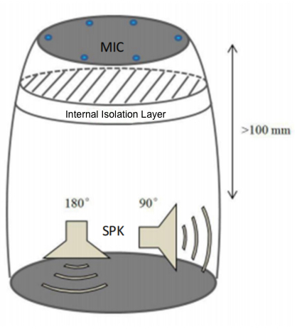
Isolation design of microphone and speaker
- Place the speaker and the microphone in different chambers sealed with good-performance sealing materials, in order to prevent crosstalk within the structure.
- The speaker diaphragm and passive diaphragm do not face the microphone, and the included angle is greater than 90°.
- The speaker sound outlet is more than 100 mm away from the microphone sound inlet. The greater the distance, the better the performance.
- The sound pressure from the speaker to the microphone does not exceed 90 dB when measured at the microphone. The signal-to-noise ratio of the human voice volume and speaker volume intensity is not be lower than -15 dB. The sound pressure from the human voice to the microphone is about 65 dB.
The debugging steps are as follows:
- When the speaker is at the maximum broadcast volume, make sure that the microphone recording does not exceed the maximum amplitude.
- When the speaker is at the maximum broadcast volume, perform a wake-up test 3 to 5 meters from the microphone. The human voice needs to be appropriately increased if the distance exceeds 3 meters. If the wake-up failed, reduce the amplifier gain until the wake-up is successful.
The isolation measure looks like this:
Design of speaker chamber
During the design of a speaker chamber, avoid the abnormal sound and tremolo caused by structural resonance, and design the front and rear chambers based on the actual application scenarios, such as voice, music, and alerts.
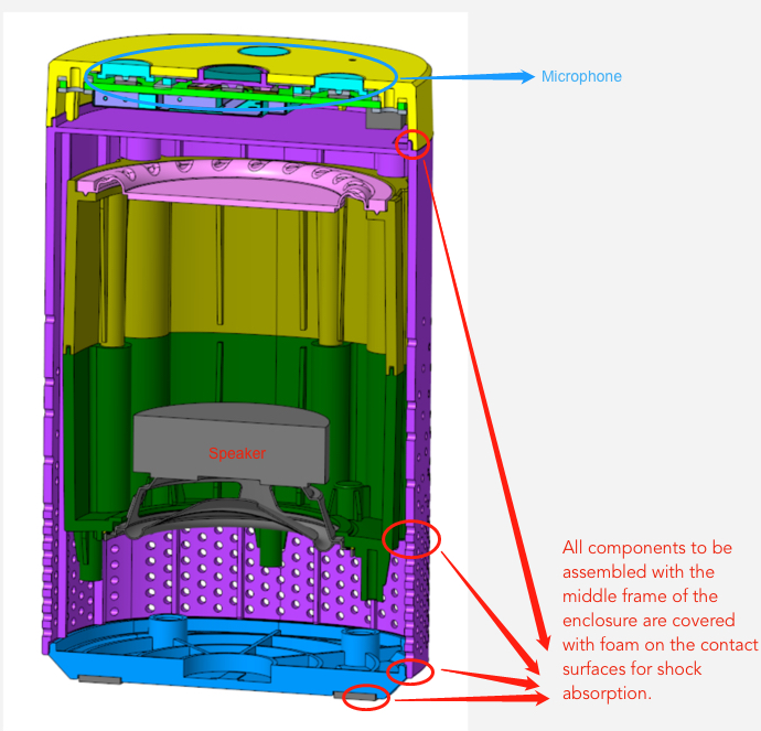
Take shock absorption treatment before assembling the speaker chamber with the whole product.
- Keep a distance of at least 2 mm between the chamber and other components, and paste shock-absorbing foams in the corners to prevent noise caused by assembly tolerances and dimensional tolerances.
- Keep a distance of at least 5 mm among the speaker diaphragm, passive diaphragm, and other parts. Refer to the maximum amplitude of the speaker,
Xmax, as specified in the speaker specification. - All components to be assembled with the middle frame of the enclosure are covered with foam on the contact surfaces for shock absorption.
- The back chamber wall of the speaker should be made of non-magnetically conductive materials with strong rigidity and great thickness. However, in some cases, the back chamber should be as large as possible to avoid material shrinkage. If a thin wall is used to balance such designs, reinforcing ribs are designed to avoid resonance in the rear chamber.
During the design of a back chamber, fully consider the application scenarios to optimize the acoustic performance.
- Choose a suitable speaker unit. For example, a smart speaker has a music and voice feature, 3W, 5W, and10W high power, low distortion, and low F0). A smart camera has a far-field voice feature, 3W and 5W high power, and excellent intermediate frequency performance). An alarm has ultra-large power and sends a piercing sound with high frequency.
- Seal the front and back chambers to prevent acoustic short circuits that might lead to reduced sensitivity, especially low-frequency sensitivity.
- Seal the back chamber to prevent sound leakage.
- Considering the application scenarios and speakers, determine the size of the back chamber for optimal acoustic performance. For example, for smart speakers, select low F0 speakers, improve low-frequency sound pressure level (SPL), and maximize the back chamber based on the actual box. Also, a passive diaphragm design is adopted to improve the low-frequency performance of the speaker.
- When a passive diaphragm is used in the back chamber of the speaker, fully consider whether the material of the passive diaphragm is magnetically conductive and whether it will affect the speaker performance.
During the design of a front chamber, fully consider the application scenarios to optimize the acoustic performance.
-
The sound channel of the front chamber should be as smooth as possible, without sharp angles. Abrupt angles should be rounded, if any.
-
If the vibration surface of the speaker diaphragm faces the surface where the product is placed, such as a desk for a smart speaker, prepare a sound guide cone in the front chamber, in order to guide the sound smoothly around the bottom.
-
Make sound outlets as many as possible, accounting for 8% to 20% of the speaker diaphragm area. This is a reference design value.
-
If the speaker’s high-frequency sound is sharp and noisy, carry out suppression treatment. The sound outlet channel can be bent, but the interior should have a smooth transition. Moreover, make sound outlets at the sides and simulate the front chamber pipeline to guarantee a proper cut-off frequency. A too long and large pipeline leads to a low cut-off frequency and narrow frequency width.
-
When a circular speaker is used in a mobile phone,a circular sound outlet is recommended. Otherwise, due to the difference in the shape of the vibrating body and the sound outlet, the frequency characteristics will change and the sound will become sharp.
Type selection
Typically, speech recognition products require an external echo cancellation circuit. The sampling point is preferably the rear stage of the power amplifier (speaker end).
Microphone type selection
The following basic principles are recommended for microphone array design:
- A more number of microphones indicates better sound reception and anti-noise effect, but higher costs. Confirm the number of microphones as needed.
- There are ring arrays and line arrays. In a ring array, try to place microphones at equal intervals. The array diameter range is matched according to the signal processing algorithm.
- If not restricted by the structure, the ring array is preferred. Due to the effect of array beams, a line array is subject to a large angle recognition deviation in the axis direction.
Recommended performance metrics:
-
Sensitivity: -38 dBV to -42 dBV ± 1.5 dBV for an analog microphone, and -26 dBFS ± 1.5 dBFS for a digital microphone.
-
Signal-to-noise ratio (SNR): ≥65 dB
-
Total harmonic distortion (THD): ≤ 1% (1 kHz)
-
Acoustic overload point (AOP): ≥120 dBSPL
-
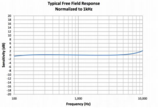
The response fluctuation of the free field spectrum (from 100 Hz to 10 kHz) is less than 3 dB. The typical situation is shown as follows.
Speaker type selection
The following principles are recommended for the type selection of speaker units:
- The THD of a speaker unit should be as small as possible. The smaller the THD, the better the acoustic echo cancellation (AEC) effect, and the higher the interrupt wake-up rate.
- The maximum volume of the system should not exceed the rated power of the speaker unit.
- After the speaker is assembled into the end product, the sound pressure level should meet the requirements of product use and listening evaluation.
- The rated power and impedance of the speaker should match the power of the amplifier to produce the desired sound.
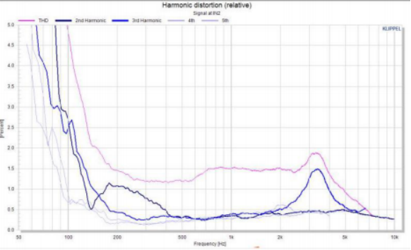
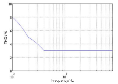
- Select your desired speaker based on the application scenarios, as specified in the speaker chamber design. For example, a smart speaker should choose a speaker unit with low harmonic distortion, we recommend that at the rated power, THD ≤ 8% to 5% at 100Hz to 200Hz, THD ≤ 5% to 3% at 200 Hz to 400 Hz, and THD ≤ 3% at 400 Hz to 8,000 Hz.
Usually, speakers have large harmonic distortion at low frequencies. In case of failure to meet the requirements, the following operations can be performed:
- Check whether there is sound leakage in the back chamber of the speaker.
- Check whether the diaphragm of the speaker unit is subject to deflection or vibration.
- Adjust the equalizer (EQ) to reduce low-frequency energy but at the cost of volume and subjective listening.
- Replace the speaker unit.
The following figure shows the THD curve of a speaker at the rated power:
Target values of component tests
-
Microphone inlet frequency response and THD:
- The frequency response fluctuation of each microphone in the 100 to 8,000 Hz frequency band is ≤ 6 dB.
- Microphone array: at each frequency point in the 100 to 8,000 Hz frequency band, the difference among all microphones is 3 dB or less.
- Regarding each microphone, the THD is no more than 1.5% in the 100 to 200 Hz frequency band and no more than 1% in the 200 to 8,000 Hz frequency band.
-
The THD of playing sound and recording. Regarding each microphone, the THD is no more than 8% in the 100 to 200 Hz frequency band, less than 5% in the 200 to 400 Hz frequency band, and no more than 3% in the 400 to 8,000 Hz frequency band.
-
The THD of the whole speaker: The requirement is the same as that in the playing sound and recording test.
Waterproof design
Waterproof design of the microphone
Determine whether to add a dust-proof and waterproof membrane.
-
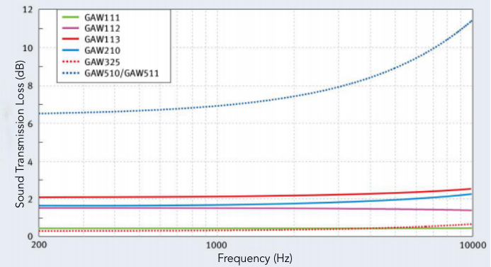
To select a model, ask the supplier for the product specification and submit it to Tuya. The following figure is an example of the sound transmission loss of the dust-proof and waterproof membrane. The green line has a flat frequency response, and the sound transmission loss is small in each frequency band. Therefore, this is a better model.
-
In the pickup channel, make sure the sealing layer completely wraps the dust-proof and waterproof membrane. The diameter of the sealing layer is larger than the diameter of the membrane.
The left-side figure shows a wrong design, and the right-side figure shows a correct design.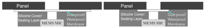
-
Pay special attention to the loss of sound transmission after the dust-proof and waterproof membrane is compressed. In case of a large sound transmission loss, you can replace the sealant with foam of a higher compression ratio and reduce the foam thickness appropriately. Minimize the pressure on the membrane while ensuring airtightness.
Waterproof design of the speaker
- Select a waterproof speaker unit.
- The box adopts a waterproof design based on the selected speaker unit. The upper and lower enclosures shall be airtight.
- The sound outlet faces the part in the gravity direction of the product. The sound outlet is designed to be large inside and small outside, so water inflow is difficult while water outflow is easy.
- The front chamber of the speaker is as small as possible to reduce the accumulation of water. The vibration of the speaker diaphragm helps to easily discharge the water.
- If the waterproof design of the speaker does not meet the waterproof requirements of the finished product, you can select a waterproof membrane with less sound loss.
PCB design
Microphone layout
-
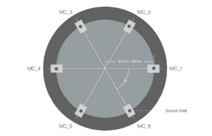
Facing the microphone pickup chamber, the microphones are arranged counterclockwise. The following figure shows the ring layout of six microphones, with a 60° included angle.

-
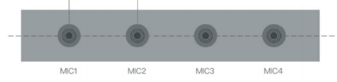
Facing the microphone pickup chamber, the microphones are arranged from left to right. The pickup chamber is placed on the same horizontal line. The following figure shows four microphones in a line.
Microphone spacing
-
Regarding the 6-microphone ring layout, the microphone diameter can be 40 mm to 72 mm measured at the center point of the pickup chamber, and the optimal diameter is 60 mm, as shown in the following figure:
-
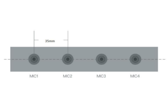
Regarding the 4-microphone linear layout, the microphone spacing can be 25 mm to 45 mm, preferably 35 mm, as shown in the figure below:
-
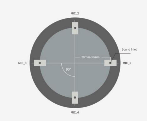
Regarding the 4-microphone ring layout, the microphone diameter can be 40 mm to 72 mm, and the optimal diameter is 60 mm, as shown in the following figure:
-
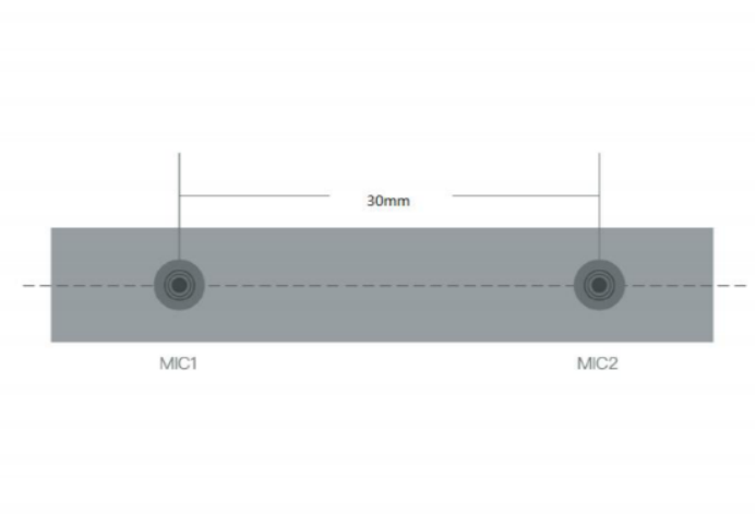
Regarding the 2-microphone linear layout, the microphone spacing can be 20 mm to 40 mm, preferably 30 mm, as shown in the figure below:
Microphone circuit layout
In an analog microphone, the DC blocking circuit should be placed close to the microphone.
Isolation of analog ground from digital ground
As the case may be, the isolation design is recommended for a more stable power supply ground.
Driver
Android system driver migration:
For the Android system, Tuya needs to migrate the algorithm patch in the hardware abstraction layer (HAL).
Provide the following information:
-
The processor model and specification.
-
The model and specification of microphone array acquisition codec.
-
The Android version number.
-
The system information. For an Android system, provide
/proc/cpu info,/proc/asound/pcm, and/system/etc/audio_policy_conf. For an Android 8 system or later, provideaudio_policy_configuration.xmland relevant files. -
The microphone array acquisition solution. For example, which microphone solution is used, how many loopbacks are used, and how to get microphone and loopback signals.
-
The
tinycaprecording commands and recorded audio. The audio content requires background music playback and human voice, and the recording duration is more than 30 seconds.
Audio format: 16K 16-bit PCM or WAV.Audio data can also be 16K 32-bit, 32K 32-bit, and more.
Linux system driver
For the Linux system, Tuya will assist you in debugging related audio capture drivers.
Provide the following information:
- The processor model and specification.
- The model and specification of microphone array acquisition codec.
- The cross-compilation toolchain.
- The microphone array acquisition solution. For example, which microphone solution is used, how many loopbacks are used, and how to get microphone and loopback signals.
- Audio format: 16K 16-bit PCM or WAV.
Audio data can also be 16K 32-bit, 32K 32-bit, and more.
Anomaly analysis: microphone circuit layout
Microphone
- Low wakeup rate and recognition rate
- Optimize the microphone array.
- Optimize performance parameters of the microphone unit, including sensitivity, SNR, and directivity.
- Check whether the speaker interferes with the microphone.
- Optimize the microphone algorithm.
- Discrete sensitivity curve
- Check the microphone sound inlet for foreign objects.
- Check whether the dust-proof and waterproof membrane works properly.
- Check the SPL consistency of the microphone unit.
- Squeal
- Keep the speaker and microphone as far away as possible.
- Check the sealing and damping performance of the silicone cover between the microphone and the enclosure, and check whether any interference is caused by sound transmission to the microphone through vibration.
- Check the sealing performance of the glue between the microphone and the enclosure interior, and check whether there is any interference caused by internal sound transmitted to the microphone.
- Add an echo cancellation algorithm to filter out the speaker sound received by the microphone.
- Appropriately reduce the gain of the speaker.
Speaker
- Low sensitivity of the speaker
- Turn up the speaker volume.
- Check whether the sound transmission of the speaker sound outlet is suitable and whether the sound outlet is blocked.
- Check whether the SPL of the speaker unit is qualified.
- To suit specified application scenarios, check whether the performance of the power amplifier is satisfactory, and then use a higher-power speaker. Double the distance, and the sound pressure level will be reduced by 6 dB.
- Noise
- Noise in the speaker unit: Replace the speaker unit, check whether the distance design of the speaker diaphragm structure is appropriate, and check whether the speaker assembly is skewed.
- Resonance noise in the speaker chamber: Check whether the design strength of the speaker chamber is sufficient.
- Collision noise in the speaker chamber: Check whether the distance design of the passive diaphragm structure is appropriate. For the purpose of damping, apply the foam to the contact surface or adjoining positions between the speaker chamber and the enclosure.
- Resonance noise at other locations: Check whether the cable is covered with foam, and check whether the strength of the PCB or other structural parts is sufficient.
- Electrical design noise: Check whether changing the power supply will affect the noise.
- Poor sound quality
- Not full sound effect at low frequencies: Select a unit with a high SPL at low frequencies, enlarge the volume of the back chamber, and increase the low-frequency level of the equalizer.
- Noisy sound at high frequencies: Lower the high-frequency level of the equalizer. Transform the speaker outlet channel to lower the cutoff frequency. Add acoustic cotton to the sound outlet, in order to reduce the quality factor of the speaker. Also, reduce the quality factor of the speaker unit.
- Large distortion: Check the sealing of the back chamber for any sound leakage, and check whether there is any skew vibration in the diaphragm of the speaker unit. Adjust the equalizer to reduce the energy of a specified frequency band. Add acoustic cotton to the outlet channel to reduce the quality factor of the speaker.
Poor quality during calls
- Echo
- Check the sealing performance inside the microphone.
- Check the sealing performance inside the speaker.
- Check whether the distance between the speaker and the microphone is appropriate.
- Optimize the echo cancellation algorithm.
- Poor talk quality
- Optimize the echo cancellation algorithm.
- Check the microphone and the speaker structure.
- Replace the microphone and speaker unit.
- Squeal
- Keep the speaker and microphone as far away as possible.
- Check the sealing and damping performance of the silicone cover between the microphone and the enclosure, and check whether any interference is caused by sound transmission to the microphone through vibration.
- Check the sealing performance of the glue between the microphone and the enclosure interior, and check whether there is any interference caused by internal sound transmitted to the microphone.
- Add an echo cancellation algorithm to filter out the speaker sound received by the microphone.
- Appropriately reduce the gain of the speaker.
Is this page helpful?
YesFeedbackIs this page helpful?
YesFeedback


