Offline Voice I2C Protocol of Wi-Fi Module
This topic describes the offline voice I2C protocol of Wi-Fi modules. It is suitable for developers who use Tuya offline voice modules for MCU development.
Communication convention
-
Communication rate: 100 Kbit/s
-
Bus address: 0x64
-
Communication data line: SCL, SDA
-
Data interrupt pin:
INT_PIN(Pin is pulled up, when the voice module needs to actively send data to the IoT module, a low level of 100 ms is generated to inform the IoT module that there is data to send) -
Data transfer volume: a single piece of data cannot exceed 256 bytes.
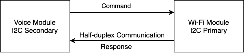
The Wi-Fi module acts as the primary, and the voice module acts as the secondary. The primary actively queries the status of the secondary, and the secondary responds to the primary with the latest status information after receiving the command.
Frame format
| Field | Bytes | Description |
|---|---|---|
| Header | 2 | It is fixed as 0x55aa. |
| Version | 1 | It is used for update and extension. |
| Command | 1 | Frame type. |
| Data length | 2 | Big-endian. |
| Data | N | - |
| Checksum | 1 | Add up all bytes starting from the header and divide the sum by 256 to get the remainder. |
- All data greater than one byte shall be transmitted with big-endian mode.
- Generally, the same command adopts synchronous sending and receiving mechanism. One party sends a command, and the other party responds.
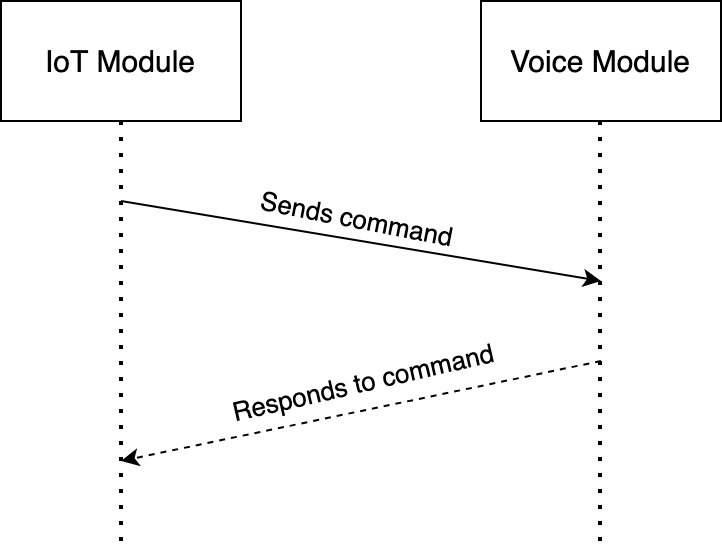
Scene 1
The IoT module actively sends a command, and the voice module responds immediately after receiving the command (within 50 ms).
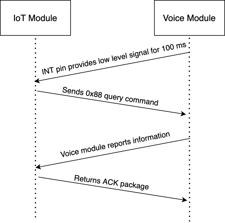
Scene 2
If the voice module wants to actively report messages to the IoT module, the following steps are required.
-
The voice module needs to pull the INT pin low for 100 ms to generate a 100 ms low-level pulse.
-
After the IoT module receives the interrupt signal, it uses the
0x88command to query the status change of the voice module. -
The voice module responds with information about the status change.
-
The IoT module replies to the voice module that it has received a state change message.
Protocol details
The table below lists commands for I2C communication.
| Command | Feature | Description |
|---|---|---|
| 0x00 | Heartbeat detection | The IoT module sends a heartbeat to the offline voice module every 5s. |
| 0x01 | Query version | The IoT module sends the 0x01 command to get the software and hardware version information of the voice module. |
| 0x03 | Wi-Fi network status of IoT module | The IoT module sends the Wi-Fi network status to the voice module. |
| 0x04 | Reset Wi-Fi and switch network pairing mode | Enter EZ pairing when the IoT module is reset, and enter AP pairing when it is reset again. |
| 0x05 | Reset Wi-Fi and switch network pairing mode | You can specify which pairing mode the IoT module enters when resetting. |
| 0x06 | DP status reporting | The offline voice module reports the DP control to the IoT module. After the IoT module receives the data, the command is forwarded to the MCU to control the DP execution. |
| 0x07 | DP status issuing | The IoT module synchronizes the DP information to the voice module. |
| 0x08 | Query the DP information | The voice module sends commands to actively query and synchronize all DP information of the MCU. |
| 0x63 | Audio production test | Set the voice internal loop test mode of the offline voice module. |
| 0x64 | Wake-up production test | Set the wake-up test mode of the offline voice module. |
| 0x65 | Set and report voice parameters | Set offline voice module parameters and actively report them. |
| 0x66 | Speech recognition text reporting | The voice module provides speech recognition text in Unicode format to the IoT module. |
| 0x67 | Issuing text verification results | The IoT module informs the voice module of the result of the voice and text verified by the platform in Unicode format. |
Status query
- After the Wi-Fi module is powered on, it periodically sends a command (
0x88) at 5s intervals to query the status of the voice module. If the voice module status changes, the latest status information will be returned to the Wi-Fi module. If there is no status change, the heartbeat information (0x00) will be returned. If the Wi-Fi module has received the first heartbeat information, and the voice module does not respond within the 90-second timeout period, the module considers a communication exception occurred and will restart the software. - In order to reduce the amount of interactive data, the query interval is set to 5 seconds, which may cause the delay for the Wi-Fi module to receive voice commands. In order to solve this problem, an interrupt method is adopted to add a data trigger I/O. When the voice module has a new state, this I/O will be triggered to be low level. At this time, the Wi-Fi module will immediately send a
0x88query command to query the voice status after detecting the low level. The voice module will upload the changed information to the Wi-Fi module according to the status type.
The Wi-Fi module sends the following command:
| Field | Bytes | Description |
|---|---|---|
| Header | 2 | 0x55aa |
| Version | 1 | 0x00 |
| Command | 1 | 0x88 |
| Data length | 2 | 0x0000 |
| Data | 0 | None |
| Checksum | 1 | Add up all bytes starting from the header and divide the sum by 256 to get the remainder. |
For example, 0x55 aa 00 88 00 00 87
The voice module returns the following command:
The voice module will decide what data to send based on whether there is a current status change. For example, if there is a user’s voice request to reset the network, the voice module will send the 0x05 command. If the DP is reported, then the 0x06 command will be sent. If the current status of the voice module has not changed, then send the 0x00 heartbeat command as the heartbeat to the Wi-Fi module as a reply.
Heartbeat
If the voice module has no status change, it will reply to the heartbeat message.
The voice module returns the following command:
| Field | Bytes | Description |
|---|---|---|
| Header | 2 | 0x55aa |
| Version | 1 | 0x03 |
| Command | 1 | 0x00 |
| Data length | 2 | 0x0001 |
| Data | 1 | 0x00: the return value of the first heartbeat after the voice module reboots. It is only sent once, used for the module to determine whether the MCU reboots during the working process. 0x01: this value is returned except for the first return value of 0 after the voice module reboots. |
| Checksum | 1 | Add up all bytes starting from the header and divide the sum by 256 to get the remainder. |
For example,
For example, the voice module returns 0x55aa 03 00 0001 00 03 after a restart.
Returns 0x55aa 03 00 0001 01 04 except for the first response after a restart.
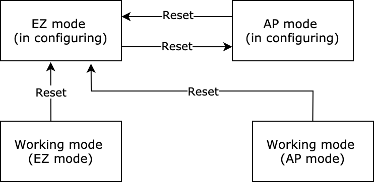
Reset Wi-Fi
Status transfer of resetting Wi-Fi is shown as follows:
The voice module sends the following command:
| Field | Bytes | Description |
|---|---|---|
| Header | 2 | 0x55aa |
| Version | 1 | 0x03 |
| Command | 1 | 0x04 |
| Data length | 2 | 0x0000 |
| Data | 0 | None |
| Checksum | 1 | Add up all bytes starting from the header and divide the sum by 256 to get the remainder. |
For example, 0x55aa 03 04 0000 06
Reply the voice module that a Wi-Fi resetting command is received.
The Wi-Fi module sends the following command:
| Field | Bytes | Description |
|---|---|---|
| Header | 2 | 0x55aa |
| Version | 1 | 0x00 |
| Command | 1 | 0x04 |
| Data length | 2 | 0x0000 |
| Data | 0 | None |
| Checksum | 1 | Add up all bytes starting from the header and divide the sum by 256 to get the remainder. |
For example, 0x55aa 00 04 0000 03
Reset Wi-Fi and select configuration mode
With this frame, the voice module can select the required configuration mode after the Wi-Fi is reset.
The voice module sends the following command:
| Field | Bytes | Description |
|---|---|---|
| Header | 2 | 0x55aa |
| Version | 1 | 0x03 |
| Command | 1 | 0x05 |
| Data length | 2 | 0x0001 |
| Data | 1 | 0x00: enter SmartConfig pairing mode |
| Checksum | 1 | Add up all bytes starting from the header and divide the sum by 256 to get the remainder. |
For example, 0x55aa 03 05 0001 00 08, enter SmartConfig pairing mode.
Reply the voice module that a command of resetting Zigbee-selecting configuration mode is received.
The Wi-Fi module sends the following command:
| Field | Bytes | Description |
|---|---|---|
| Header | 2 | 0x55aa |
| Version | 1 | 0x00 |
| Command | 1 | 0x05 |
| Data length | 2 | 0x0000 |
| Data | 0 | None |
| Checksum | 1 | Add up all bytes starting from the header and divide the sum by 256 to get the remainder. |
For example, 0x55aa 00 05 0000 03
DP control reporting
Data point command and status data unit is shown as follows:
| Data segment | Bytes | Description | |||
|---|---|---|---|---|---|
| dpid | 1 | Data point serial number. | |||
| type | 1 | The specific data type of a data point on the Developer Platform, which is marked with the following "Value". | |||
| Type | Value | Length (byte) | Description | ||
| raw | 0x00 | N | Corresponding to raw data point (module pass-through). | ||
| bool | 0x01 | 1 | Value range: 0x00/0x01. | ||
| Value | 0x02 | 4 | Corresponding to the integer type, which is expressed in big-endian. | ||
| string | 0x03 | N | Correspond to specific strings. | ||
| enum | 0x04 | 1 | Enumeration data, ranging from 0 to 255. | ||
| bitmap | 0x05 | 1/2/4 | Represented by big-endian when there is more than one byte. | ||
| len | 2 | The length corresponds to the number of bytes of value. | |||
| Value | 1/2/4/N | Expressed in the hexadecimal format. Use a big-endian representation when there is more than one byte. |
- For the data point command/status data unit, except the "raw" type, all other types belong to the "obj" type data point.
- The DP command reporting can contain command data units of multiple DPs.
- The DP command reporting is an asynchronous processing protocol, corresponding to the data point status update issuing of the Wi-Fi module.
Note:
- Status reporting can contain command data units of multiple data points.
- The voice module converts the voice input by the user into the corresponding DP and sends it to the Wi-Fi module. For example, the user sets a humidity of 30% by voice, the corresponding DP point is 5, and the humidity refers to the value 30 (0x1e).
The voice module sends the following command:
| Field | Bytes | Description |
|---|---|---|
| Header | 2 | 0x55aa |
| Version | 1 | 0x03 |
| Command | 1 | 0x06 |
| Data length | 2 | It depends on the type and number of the status data unit. |
| Data | N | See the DP status data unit section. |
| Checksum | 1 | Add up all bytes starting from the header and divide the sum by 256 to get the remainder. |
For example, the humidity corresponds to DP 5, valve variable is used, and the humidity is 30%.
0x55aa 03 06 0008 05 02 0004 0000001e 39
Reply the voice module that a DP control reporting command is received.
The Wi-Fi module sends the following command:
| Field | Bytes | Description |
|---|---|---|
| Header | 2 | 0x55aa |
| Version | 1 | 0x00 |
| Command | 1 | 0x06 |
| Data length | 2 | 0x0000 |
| Data | 0 | None |
| Checksum | 1 | Add up all bytes starting from the header and divide the sum by 256 to get the remainder. |
For example, 0x55aa 00 06 0000 05
The offline voice module actively queries the network status
The voice module actively queries the network status of the Wi-Fi module through the command (0x2B), and the Wi-Fi module informs the voice module of the network status through the 0x2B command.
The voice module sends the following command:
| Field | Bytes | Description |
|---|---|---|
| Header | 2 | 0x55aa |
| Version | 1 | 0x03 |
| Command | 1 | 0x2B |
| Data length | 2 | 0x0000 |
| Data | 0 | None |
| Checksum | 1 | Add up all bytes starting from the header and divide the sum by 256 to get the remainder. |
For example, 0x55aa 03 2B 0000 2D
The Wi-Fi module returns the device network status as follows.
| Device network status | Description | Status value |
|---|---|---|
| Status 1 | SmartConfig configuration status | 0x00 |
| Status 2 | AP configuration status | 0x01 |
| Status 3 | Wi-Fi has been configured but not connected to the router. | 0x02 |
| Status 4 | Wi-Fi has been configured and connected to the router. | 0x03 |
| Status 5 | Wi-Fi has been connected to the router and the cloud. | 0x04 |
| Status 6 | Wi-Fi device is in the low power mode. | 0x05 |
The Wi-Fi module sends the following command:
| Field | Bytes | Description |
|---|---|---|
| Header | 2 | 0x55aa |
| Version | 1 | 0x00 |
| Command | 1 | 0x2B |
| Data length | 2 | 0x0001 |
| Data | 1 | 0x00: indicates SmartConfig configuration status 0x01: indicates AP configuration status 0x02: indicates Wi-Fi is configured but not connected to the router 0x03: indicates Wi-Fi is configured and connected to the router 0x04: indicates the device is connected to the router and the cloud 0x05: indicates Wi-Fi device is in low power mode |
| Checksum | 1 | Add up all bytes starting from the header and divide the sum by 256 to get the remainder. |
For example, 0x55aa 00 2B 0001 04 2F. The IoT module is connected to the cloud. |
The offline voice module queries Wi-Fi strength
The voice module actively queries the Wi-Fi signal strength through the command (0x24), and the Wi-Fi module informs the voice module of the signal strength through the 0x24 command.
The voice module sends the following command:
| Field | Bytes | Description |
|---|---|---|
| Header | 2 | 0x55aa |
| Version | 1 | 0x03 |
| Command | 1 | 0x24 |
| Data length | 2 | 0x0000 |
| Data | 0 | None |
| Checksum | 1 | Add up all bytes starting from the header and divide the sum by 256 to get the remainder. |
For example, 0x55aa 03 24 0000 26
The Wi-Fi module returns the signal strength to the voice module.
The Wi-Fi module sends the following command:
| Field | Bytes | Description |
|---|---|---|
| Header | 2 | 0x55aa |
| Version | 1 | 0x00 |
| Command | 1 | 0x24 |
| Data length | 2 | 0x0001 |
| Data | 1 | 0x00: indicates failure. Less than 0: indicates signal strength, such as -60 dB. |
| Checksum | 1 | Add up all bytes starting from the header and divide the sum by 256 to get the remainder. |
For example, 0x55aa 00 24 0001 80 A4
Voice recognition text reporting
- The text is in character format. For example, I am going home. The text message is "I am going home", and the voice module transmits these data directly.
- The voice text information is sent to the Wi-Fi module through the
0x66command, and the Wi-Fi module directly responds to the0x66command after receiving it to inform the voice module that the command has been received. After that, the text information is uploaded to the platform through the 501 protocol to verify the text. After receiving the reply from the platform, the Wi-Fi module informs the voice module of the result of the text verification through the0x67command.
The voice module sends the following command:
| Field | Bytes | Description |
|---|---|---|
| Header | 2 | 0x55aa |
| Version | 1 | 0x03 |
| Command | 1 | 0x66 |
| Data length | 2 | 0x0012 |
| Data | 2 | Voice text ID. The voice module can correspond to unique scene commands through ID. For example, the ID corresponding to "home mode" is 00 01. |
| 2 | Country code, used to identify the language of which country the following characters are, such as China "CN", United States "US". | |
| N | The total data length does not exceed 256 bytes. For example, Chinese: “回家场景”, English: "good night mode". | |
| Checksum | 1 | Add up all bytes starting from the header and divide the sum by 256 to get the remainder. |
Country code standards. See Mappings Between OEM App Accounts and Data Centers.
For example, home scene, ID is 00 01.
55 aa 03 66 00 10 00 01 43 4e e5 9b 9e e5 ae b6 e5 9c ba e6 99 af da
After the Wi-Fi module receives the text information of the voice module, it will be sent to the platform to verify whether the scene is valid.
The Wi-Fi module sends the following command:
| Field | Bytes | Description |
|---|---|---|
| Header | 2 | 0x55aa |
| Version | 1 | 0x03 |
| Command | 1 | 0x66 |
| Data length | 2 | 0x0000 |
| Data | N | None |
| Checksum | 1 | Add up all bytes starting from the header and divide the sum by 256 to get the remainder. |
For example, 55 aa 00 66 00 00 65
Query the DP information
The voice module actively queries the DP information of the MCU through the command (0x08), and the Wi-Fi module queries the DP information of the MCU, and transparently transmits it to the voice module.
The voice module sends the following command:
| Field | Bytes | Description |
|---|---|---|
| Header | 2 | 0x55aa |
| Version | 1 | 0x03 |
| Command | 1 | 0x08 |
| Data length | 2 | 0x0000 |
| Data | 0 | None |
| Checksum | 1 | Add up all bytes starting from the header and divide the sum by 256 to get the remainder. |
For example, 0x55aa 03 08 0000 0A
The Wi-Fi module replies the voice module.
The Wi-Fi module sends the following command:
| Field | Bytes | Description |
|---|---|---|
| Header | 2 | 0x55aa |
| Version | 1 | 0x00 |
| Command | 1 | 0x08 |
| Data length | 2 | 0x0000 |
| Data | 0 | None |
| Checksum | 1 | Add up all bytes starting from the header and divide the sum by 256 to get the remainder. |
For example, 0x55aa 00 08 0000 07
The IoT module sends the network status to the voice module
| Device network status | Description | Status value |
|---|---|---|
| Status 1 | SmartConfig configuration status | 0x00 |
| Status 2 | AP configuration status | 0x01 |
| Status 3 | Wi-Fi has been configured but not connected to the router. | 0x02 |
| Status 4 | Wi-Fi has been configured and connected to the router. | 0x03 |
| Status 5 | Wi-Fi has been connected to the router and the cloud. | 0x04 |
| Status 6 | Wi-Fi device is in the low power mode. | 0x05 |
- Device network status:
- 1: SmartConfig configuration status
- 2: AP configuration status
- 3: Wi-Fi has been successfully configured but not connected to the router.
- 4: Wi-Fi has been successfully configured and connected to the router.
- 5: The device has been connected to the router and the cloud. The status of LED indicator in module self-processing mode.
- Status 1: flicker at 250 milliseconds intervals.
- Status 2: flicker at 1,500 milliseconds intervals.
- Status 3: always off.
- Status 4 or 5: always on.
- When the module detects that the voice module reboots or is disconnected and then go back online, it will send the Wi-Fi status to the voice module.
- When the Wi-Fi status of the module changes, it will send the Wi-Fi status to the voice module.
- If the module working mode is set to module self-processing, the voice module does not need to implement this protocol.
The Wi-Fi module sends the following command:
| Field | Bytes | Description |
|---|---|---|
| Header | 2 | 0x55aa |
| Version | 1 | 0x00 |
| Command | 1 | 0x03 |
| Data length | 2 | 0x0001 |
| Data | 1 | Indicates Wi-Fi working status: 0x00: status 1, 0x01: status 2, 0x02: status 3, 0x03: status 4, 0x04: status 5, and 0x05: status 6. |
| Checksum | 1 | Add up all bytes starting from the header and divide the sum by 256 to get the remainder. |
For example, 0x55aa 00 03 0001 00 03
The voice module returns the following command:
| Field | Bytes | Description |
|---|---|---|
| Header | 2 | 0x55aa |
| Version | 1 | 0x03 |
| Command | 1 | 0x03 |
| Data length | 2 | 0x0000 |
| Data | 0 | None |
| Checksum | 1 | Add up all bytes starting from the header and divide the sum by 256 to get the remainder. |
For example, 0x55aa 03 03 0000 05. Reply to the pairing status command.
Set, query, and report voice parameters
- Extend the functions of voice module: Add status notification and settings of play/pause, Bluetooth on/off, local alarm clock, and voice control group.
- Play/pause: play and pause music, poems, and jokes.
- Bluetooth on/off: turn on/off Bluetooth speaker.
- Local alarm clock: synchronization notification of the clock data set by the voice and app.
- Voice control group: notification of voice control command of the previous/next song.
- MIC on/off: turn on/off MIC, and report the MIC status changes.
- Volume setting: set the volume of the voice module and actively report the volume change.
The Wi-Fi module sends the following command:
| Field | Bytes | Description |
|---|---|---|
| Header | 2 | 0x55aa |
| Version | 1 | 0x00 |
| Command | 1 | 0x65 |
| Data length | 2 | xx |
| Data | 1 | Sub-command: 0x00 |
| Data | Data: { "mic":true, "volume":8, "play":true, "bt_play":true, "alarm":”xxxx”, "ctrl_group":”xxxx” } | mic: microphone on/off function. true: turn on the microphone. false: turn off the microphone. volume: volume ranging from 0 to 100. play: play/pause function. True is for play, and false is for pause. bt_play: Bluetooth on/off function. True is for on, and false is for off. alarm: local alarm clock. xxx is string. ctrl_group: voice control group."xxx" is string. |
| Checksum | 1 | Add up all bytes starting from the header and divide the sum by 256 to get the remainder. |
The voice module returns the following command:
| Field | Bytes | Description |
|---|---|---|
| Header | 2 | 0x55aa |
| Version | 1 | 0x03 |
| Command | 1 | 0x65 |
| Data length | 2 | 0x02 |
| Data | 1 | Sub-command: 0x00 |
| Data | 1 | Result: 0x00: indicates success. 0x01: indicates failure. |
| Checksum | 1 | Add up all bytes starting from the header and divide the sum by 256 to get the remainder. |
Status notification: The offline voice module actively reports the status
The voice module sends the following command:
| Field | Bytes | Description |
|---|---|---|
| Header | 2 | 0x55aa |
| Version | 1 | 0x00 |
| Command | 1 | 0x65 |
| Data length | 2 | 1+N |
| Data | 1 | Sub-command: 0x01 |
| Data | Data: { "mic":true, "volume":8, "play":true, "bt_play":true, "alarm":”xxxx”, "ctrl_group":”xxxx” } | mic: microphone on/off function. true: turn on the microphone. false: turn off the microphone. volume: volume ranging from 0 to 10. play: play/pause function. True is for play, and false is for pause. bt_play: Bluetooth on/off function. True is for on, and false is for off. alarm: local alarm clock. xxx is string. ctrl_group: voice control group."xxx" is string. |
| Checksum | 1 | Add up all bytes starting from the header and divide the sum by 256 to get the remainder. |
The Wi-Fi module sends the following command:
| Field | Bytes | Description |
|---|---|---|
| Header | 2 | 0x55aa |
| Version | 1 | 0x03 |
| Command | 1 | 0x65 |
| Data length | 2 | 2 |
| Data | 1 | Sub-command: 0x01 |
| Data | 1 | Result: 0x00: indicates success. 0x01: indicates failure. |
| Checksum | 1 | Add up all bytes starting from the header and divide the sum by 256 to get the remainder. |
Status notification: The IoT module actively queries the status
The Wi-Fi module sends the following command:
| Field | Bytes | Description |
|---|---|---|
| Header | 2 | 0x55aa |
| Version | 1 | 0x03 |
| Command | 1 | 0x65 |
| Data length | 2 | 0x0001 |
| Data | 1 | Sub-command: 0x02 |
| Checksum | 1 | Add up all bytes starting from the header and divide the sum by 256 to get the remainder. |
The voice module returns the following command:
| Field | Bytes | Description |
|---|---|---|
| Header | 2 | 0x55aa |
| Version | 1 | 0x00 |
| Command | 1 | 0x65 |
| Data length | 2 | 1+N |
| Data | 1 | Sub-command: 0x02 |
| Data | Data: { "mic":true, "volume":8, "play":true, "bt_play":true, "alarm":”xxxx”, "ctrl_group":”xxxx” } | mic: microphone on/off function. true: turn on the microphone. false: turn off the microphone. volume: volume ranging from 0 to 10. play: play/pause function. True is for play, and false is for pause. bt_play: Bluetooth on/off function. True is for on, and false is for off. alarm: local alarm clock. xxx is string. ctrl_group: voice control group."xxx" is string. |
| Checksum | 1 | Add up all bytes starting from the header and divide the sum by 256 to get the remainder. |
Query product information
- Product information consists of the product ID and MCU software version number.
- MCU software version format: It is expressed in dot-decimal notation,
x.x.x(0 ≤ x ≤ 99), andxis a decimal digit.
The Wi-Fi module sends the following command:
| Field | Bytes | Description |
|---|---|---|
| Header | 2 | 0x55aa |
| Version | 1 | 0x00 |
| Command | 1 | 0x01 |
| Data length | 2 | 0x0000 |
| Data | 0 | None |
| Checksum | 1 | Add up all bytes starting from the header and divide the sum by 256 to get the remainder. |
For example, 0x55aa 00 01 0000 00
The voice module returns the following command:
| Field | Bytes | Description |
|---|---|---|
| Header | 2 | 0x55aa |
| Version | 1 | 0x03 |
| Command | 1 | 0x01 |
| Data length | 2 | N |
| Data | N | {"H":"1.0.0","s":"1.0.0","w":"Tuya Voice Service"} |
| Checksum | 1 | Add up all bytes starting from the header and divide the sum by 256 to get the remainder. |
For example, {"h":"1.0.0","s":"1.0.0","w":"Tuya Voice Service"}
Product information field description:
-
Software and hardware version number format: the main version number. sub-version number. stage version number
-
Main version number: When the module function has major changes, such as adding multiple modules or the overall structure changes. The change of the version number is determined by the project.
-
Sub-version number: When there are certain additions or changes in functions, such as adding permission control and adding custom views. The change of the version number is determined by the project.
-
Stage version number: Generally, it is a bug fix or some small changes. The revised versions are released frequently, and the time interval is not limited. After a serious bug can be repaired, a revised version can be released. The change of the version number is determined by the project manager.
-
Hardware model:
- VCT1 module: 1.0.0 means that the main version number is 1
- VCT2 module: 2.0.0 means that the main version number is 2
-
hrepresents VCT1 module’s hardware version number, which is 1.0.0. -
srepresents software version number, which is 1.0.0. -
wrepresents the wake word is Tuya Voice Service.
Synchronize the DP information to the voice module
- The status reporting can contain command data units of multiple DPs.
- The Wi-Fi module updates the MCU status information to the voice module. For example, the MCU humidity is 30%, the corresponding DP point is 5, and the humidity refers to the value 30 (
0x1e). - The transmission data sequence number is consistent in the retransmitted data frame, and the voice module can judge the TTS broadcast by the sequence number to avoid repeated TTS broadcasts due to unanswered ACK.
- DP data control source:
The Wi-Fi module sends the following command:
| Field | Bytes | Description |
|---|---|---|
| Header | 2 | 0x55aa |
| Version | 1 | 0x03 |
| Command | 1 | 0x07 |
| Data length | 2 | Depends on the type and number of data units (N+3). |
| Data | 2 | Transmission data serial number ranges from 0 to 0xfff0. When reaching 0xfff0, it starts from 0 again. Make sure that the seq value of each independent frame is unique, and the sequence number of the response frame needs to be consistent with the control frame. |
| Data | 1 | The source of data sending: 0x00: The MCU actively updates. 0x01: LAN. 0x02: WAN 0x03: scheduled tasks in LAN. 0x04: scene linkage in WAN. 0x05: reliable channels. 0x06: Bluetooth. 0x07: scene linkage in LAN. 0xF0: offline voice modules. 0xF1: others. |
| Data | N | See the DP status data unit section. |
| Checksum | 1 | Add up all bytes starting from the header and divide the sum by 256 to get the remainder. |
For example, the humidity controlled by the offline voice module corresponds to DP 5, using a valve variable, and the humidity is 30%.
0x55aa 03 07 000b 0001 f0 05 02 0004 0000001e 2e
The voice module returns the following command:
| Field | Bytes | Description |
|---|---|---|
| Header | 2 | 0x55aa |
| Version | 1 | 0x00 |
| Command | 1 | 0x07 |
| Data length | 2 | 0x0000 |
| Data | 0 | None |
| Checksum | 1 | Add up all bytes starting from the header and divide the sum by 256 to get the remainder. |
For example, return the mute status value: 55 aa 00 07 00 00 06
Audio production test
Set the voice internal loop test mode of the offline voice module.
The Wi-Fi module sends the following command:
| Field | Bytes | Description |
|---|---|---|
| Header | 2 | 0x55aa |
| Version | 1 | 0x00 |
| Command | 1 | 0x63 |
| Data length | 2 | 0x0001 |
| Data | 1 | Audio production test value. 0x00: close audio production test 0x01: mic1 audio loop test 0x02: mic2 audio loop test 0xA0: query current production test status |
| Checksum | 1 | Add up all bytes starting from the header and divide the sum by 256 to get the remainder. |
For example, 0x55aa 00 63 0001 01 64
The voice module returns the following command:
| Field | Bytes | Description |
|---|---|---|
| Header | 2 | 0x55aa |
| Version | 1 | 0x03 |
| Command | 1 | 0x63 |
| Data length | 2 | 0x0001 |
| Data | 1 | Audio production test value. 0x00: close audio production test 0x01: mic1 audio loop test 0x02: mic2 audio loop test |
| Checksum | 1 | Add up all bytes starting from the header and divide the sum by 256 to get the remainder. |
For example, 0x55aa 03 63 0001 01 08, start mic1 audio loop test.
Wake-up production test
Set the wake-up test mode of the offline voice module.
The Wi-Fi module sends the following wake-up test command:
The Wi-Fi module sends the following command:
| Field | Bytes | Description |
|---|---|---|
| Header | 2 | 0x55aa |
| Version | 1 | 0x00 |
| Command | 1 | 0x64 |
| Data length | 2 | 0x0001 |
| Data | 1 | Sub-command: 0x00 |
| Data | 0 | None |
| Checksum | 1 | Add up all bytes starting from the header and divide the sum by 256 to get the remainder. |
For example, 0x55aa 00 64 0001 00 03
The voice module returns the following command:
| Field | Bytes | Description |
|---|---|---|
| Header | 2 | 0x55aa |
| Version | 1 | 0x03 |
| Command | 1 | 0x64 |
| Data length | 2 | 0x0002 |
| Data | 1 | Sub-command: 0x00 |
| Data | 1 | Wake-up return result. 0x00: wake-up failed 1: wake-up succeeded |
| Checksum | 1 | Add up all bytes starting from the header and divide the sum by 256 to get the remainder. |
For example, 0x55aa 03 64 0001 01 08, start the wake-up production test successfully.
Voice module reports wake-up production test results:
The voice module sends the following command:
| Field | Bytes | Description |
|---|---|---|
| Header | 2 | 0x55aa |
| Version | 1 | 0x03 |
| Command | 1 | 0x64 |
| Data length | 2 | 0x0002 |
| Data | 1 | Sub-command: 0x01 |
| Data | 1 | Result: 0x00: indicates success. 0x01: indicates failure after 10s. |
| Checksum | 1 | Add up all bytes starting from the header and divide the sum by 256 to get the remainder. |
For example, 0x55aa 00 64 0001 00 03
The Wi-Fi module returns the following command:
| Field | Bytes | Description |
|---|---|---|
| Header | 2 | 0x55aa |
| Version | 1 | 0x00 |
| Command | 1 | 0x64 |
| Data length | 2 | 0x0001 |
| Data | 1 | Sub-command: 0x01 |
| Data | 0 | |
| Checksum | 1 | Add up all bytes starting from the header and divide the sum by 256 to get the remainder. |
For example, 0x55aa 03 64 0002 01 00 08, start the wake-up production test successfully.
Issuing text verification results
The Wi-Fi module sends the following command:
For example, return the verification result of the following "home scene":
55 aa 00 67 00 11 00 01 01 00 01 e5 9b 9e e5 ae b6 e5 9c ba e6 99 af 4a
It means that the platform verification of "home scene" is successful.
The voice module returns the following command:
| Field | Bytes | Description |
|---|---|---|
| Header | 2 | 0x55aa |
| Version | 1 | 0x00 |
| Command | 1 | 0x67 |
| Data length | 2 | 0x0000 |
| Data | N | None |
| Checksum | 1 | Add up all bytes starting from the header and divide the sum by 256 to get the remainder. |
Is this page helpful?
YesFeedbackIs this page helpful?
YesFeedback


