CLI Development Kit Demo
Last Updated on : 2024-08-29 07:36:50download
This topic describes a lightweight Zigbee command line interface (CLI) demo developed based on the TuyaOS platform. Through CLI interactions and serial communication protocols, it demonstrates some commonly used APIs at TuyaOS Abstraction Layer (TAL).
Overview
Features
-
Supports CLI interactions.
- Provides interaction functionality based on serial communication protocols, allowing you to input commands through a serial debugging tool to interact with the system.
-
Demonstrates and integrates APIs at TAL.
- Enables you to view and call APIs and functions at TAL, including GPIO, PWM, ADC, software timers, network management, and Zigbee data transmission and reception.
Procedure
-
Build and flash the firmware. For more information, see Build and flash the firmware to the device.
-
In the serial debugging software, connect to the serial port for flashing and authorization, configure the following parameters, and enable the serial port.
Parameter Value Baud rate 115200 Data bit 8 Stop bit 1 Parity bit None Flow control None This demo uses the serial port for flashing and authorization as the debugging serial port.
-
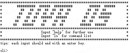
Power on the device. After the initialization is complete, the program prints the following welcome screen.
-
Input a command through the serial debugging software.
Each command must end with a carriage return.
Example
1. help Print the CLI usage guide. 2. ls Print the list of all commands. 3. nwk join_start 30000 Set the device to pairing mode with a 30-second timeout. -
The program outputs the processing result through the serial port.
Example
After you input
help, the program returns the following result: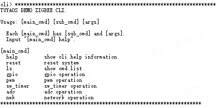
Command description
Format
Command format: main_cmd | sub_cmd | args
- One
main_cmdmay have multiplesub_cmds. sub_cmdcan be left empty.- You can refer to List of all commands to get the
main_cmd,sub_cmd, andargsdetails of each command.
Command sets
According to functionality, the commands of this demo fall into the following command sets:
-
General command set
-
The general command set provides commands for demo guidance and system control.
-
The general command set includes
main_cmdssuch ashelp(print the usage guide),reset(perform a soft reset of the system), andls(print the command list). -
sub_cmdvaries depending onmain_cmd.
For first-time users, it is recommended to refer to help command and ls command to help understand the usage and meanings of other commands.
- For more information about the command format, see List of all commands.
- For more information about the command details, see Appendix - Command reference.
-
-
GPIO command set
- The GPIO command set provides commands dedicated to GPIO.
main_cmdis fixed asgpio.sub_cmdcan beinit,deinit,write, or others. They are used to demonstrate GPIO-related APIs at TAL.
-
PWM command set
- The PWM command set provides commands dedicated to PWM.
main_cmdis fixed aspwm.sub_cmdcan beinit,deinit,start, or others. They are used to demonstrate PWM-related APIs at TAL.
-
sw_timercommand set- The sw_timer command set provides commands dedicated to
sw_timer. main_cmdis fixed assw_timer.sub_cmdcan becreate,delete,start, or others. They are used to demonstrate software timer–related APIs at TAL.
- The sw_timer command set provides commands dedicated to
-
ADC command set
- The ADC command set provides commands dedicated to ADC.
main_cmdis fixed asadc.sub_cmdcan beinit,deinit,read_single_channel, or others. They are used to demonstrate ADC-related APIs at TAL.
-
NWK command set
- The NWK command set provides commands for registering endpoints, managing networks, and reporting Zigbee data.
main_cmdis fixed asnwk.
Operations such as endpoint registration (
node_config) and pairing parameter configuration (join_config) must be processed during power-on and initialization. However, for this demo, the program provides CLI services only after power-on and initialization are complete. Therefore, some commands in thenwkcommand set only introduce how certain tasks are processed without actually processing them.For more information, see NWK command set.
help command
You can use the help command in the following three ways:
-
helpFunction: Get the CLI usage guide.

The output displays all
main_cmdssupported by this demo. -
[main_cmd] helpFunction: Get the
main_cmdusage guide.Here we use
gpio helpas an example: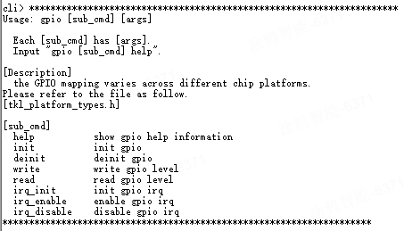
The output displays all
sub_cmdssupported by thismain_cmd. -
[main_cmd] [sub_cmd] helpFunction: Get the usage guide for the command determined by
main_cmdandsub_cmd.Here we use
gpio init helpas an example: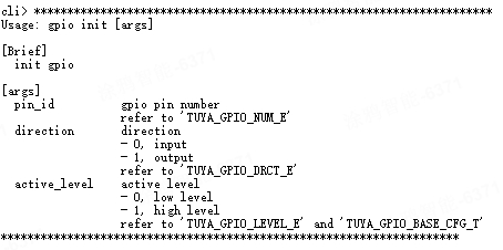
The output displays the parameter list of this command.
ls command
You can use the ls command in the following two ways:
-
lsFunction: Print the list of all commands.
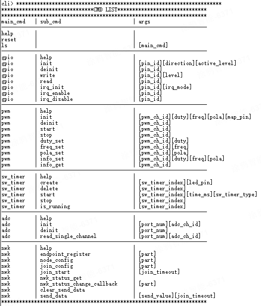
-
ls [main_cmd]Function: Print the command list of
main_cmd.Here we use
ls gpioas an example:
Create a product
For more information about how to create a product, see Create Products.
Understand the device protocol
Zigbee basics
| Parameter | Value |
|---|---|
| Profile ID | 0x0104 |
| Device ID | 0x0103 |
Endpoint description
| Endpoint | Description |
|---|---|
| 1 | The port number used by the switch. |
Supported clusters
| Input cluster (Server) | Output cluster (Client) |
|---|---|
| Basic (0x0000) | Over The Air Upgrade (0x0019) |
| Identify (0x0003) | / |
| Group (0x0004) | / |
| Scene (0x0005) | / |
| OnOff (0x0006) | / |
Supported attributes and commands
Basic cluster
Attributes
| ID | Name | Data type | Range | Default |
|---|---|---|---|---|
| 0x0000 | ZCL Version | uint8-0x20 | 0x00-0xff | 0x03 |
| 0x0001 | Application Version | uint8-0x20 | 0x00-0xff | For example, 0b 01 00 0001 = 1.0.1. That is, 0x41 represents version 1.0.1. This attribute is used for OTA updates. When an OTA update is initiated, the gateway reads the version number of the update and pushes it to the device. After the device is restarted after the update, the gateway reads the current version to check for the update result. The firmware can only be updated to a later version. |
| 0x0002 | Stack Version | uint8-0x20 | 0x00-0xff | 0x02 |
| 0x0003 | Hardware Version | uint8-0x20 | 0x00-0xff | 0x01 |
| 0x0004 | Manufacturer Name | string-0x42 | 0-32 bytes | Format: XXX…XXX. The value of this attribute is 16 bytes in length, consisting of 8-byte prefix and 8-byte PID. 0 to 7 bytes: _TZ3000_. 8 to 16 bytes: The PID, which is the unique identifier of the product you created on Tuya Developer Platform or provided by the product manager. This field determines the UI and feature display on the mobile app. You can use the default PID if you do not require a custom one. |
| 0x0005 | Model Identifier | string-0x42 | 0-32 bytes | TS000x (the switch with a neutral wire). It is used for connection to Tuya-enabled gateways, where x indicates the number of gangs. For example, TS0002 represents a two-gang switch with a neutral wire. |
| 0x0007 | Power Source | enum8-0x30 | 0x00-0xff | 0x01 |
| 0xFFFD | Cluster Revision | uint16-0x21 | 0x0000-0xffff | 0x0001 |
Commands
| ID | Name | Direction | Description |
|---|---|---|---|
| 0x00 | Reset to Factory Defaults | Client to server | Restores factory settings. |
Identify cluster
Attributes
| ID | Name | Data type | Range | Default |
|---|---|---|---|---|
| 0x0000 | identify time | uint16-0x21 | 0x0000-0xffff | 0x0000 |
Group cluster
Attributes
| ID | Name | Data type | Range | Default |
|---|---|---|---|---|
| 0x0000 | name support | bitmap8-0x18 | 0x00-0xff | 0x00 |
Commands
| ID | Name | Direction |
|---|---|---|
| 0x00 | Add group | Client to server |
| 0x03 | Remove group | Client to server |
Scene cluster
Attributes
| ID | Name | Data type | Range | Default |
|---|---|---|---|---|
| 0x0000 | Scene count | uint8-0x20 | 0x00-0xff | 0x00 |
| 0x0001 | Current scene | uint8-0x20 | 0x00-0xff | 0x00 |
| 0x0002 | Current group | uint16-0x21 | 0x0000-0xffff | 0x0000 |
| 0x0003 | Scene valid | bool-0x10 | 0x00-0xff | 0x00 |
| 0x0004 | Name support | bitmap8-0x18 | 0x00-0xff | 0x00 |
Commands
| ID | Name | Direction |
|---|---|---|
| 0x04 | Store Scene | Client to server |
| 0x05 | Recall Scene | Client to server |
On/Off cluster
Attributes
| ID | Name | Data type | Range | Default |
|---|---|---|---|---|
| 0x0000 | OnOff | bool-0x10 |
|
0x00 |
Commands
| ID | Name | Direction |
|---|---|---|
| 0x00 | Off | Client to server |
| 0x01 | On | Client to server |
Correspondence between a DP and a cluster
| DPID | DP meaning | Standard command | Corresponding endpoint |
|---|---|---|---|
| 1 | Switch | Yes | 1 |
DP switch
The gateway sends the on/off command to the device to turn on or off the device. The device reports on/off status using the standard on/off attribute.
| Direction | Cluster ID | CMD / ATTR ID | Value |
|---|---|---|---|
| Server to client | 0x0006: on/off |
|
/ |
| Client to server | 0x0006: on/off |
0x0000: on/off |
|
Build and flash the firmware to the device
Build the firmware
-
In Visual Studio Code, open the product development kit, expand
software/TuyaOS/appson the left, and find theprojectfolder of this demo.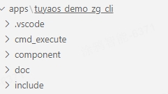
-
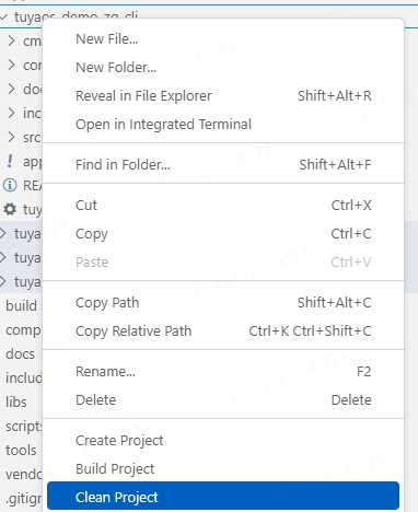
Right-click the product folder, and select Build Project. In the pop-up text box, enter the version number of the firmware to build in the format of
x.x.x. Press Enter.For the Telink chip platform, it is recommended to click Clean Project before clicking Build Project.
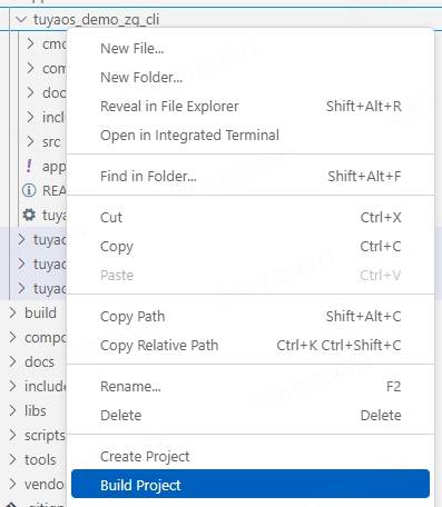

-
After the build succeeds, the console output is as follows (taking the Silicon Labs platform as an example):
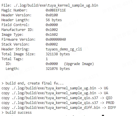
You can view the build artifacts in the
software/TuyaOS/_outputfolder. QIO indicates the flashed firmware, and UG indicates the OTA update file. Details are as follows:- The build artifacts of the Silicon Labs platform are in the
software/TuyaOS/_outputfolder. - The build artifacts of the Telink platform are in the
outputfolder under the project path. - The build artifacts of the Phyplus platform are in the
software/TuyaOS/_outputfolder.
Here we use the Silicon Labs platform as an example:

- The build artifacts of the Silicon Labs platform are in the
-
Clear the build content. For the Telink platform, it is recommended to clear the content of the previous build. Right-click the product folder, select Clean Project, enter the version number, and press Enter.

Flash the firmware
- You can flash the Silicon Labs, Telink, and Phyplus platforms using tools from the chip vendors.
- For more information about the flashing tools from Tuya and Silicon Labs, see the Flash firmware and authorize chip section in Flash Firmware and Authorize Module.
Develop a routine
Configure basic information
Configure device registration
In the app_dev_register.c file within the src folder of the project, you can modify the device registration information, including device ID, cluster, and attribute.
To add or remove registered server clusters, modify the file content shown below.
// Server cluster list
CONST TAL_CLUSTER_T onoff_ep_server_cluster_list[] = {
    DEF_CLUSTER_IDENTIFY_CLUSTER_ID(identify_attr_list)
    DEF_CLUSTER_GROUPS_CLUSTER_ID(group_attr_list)
    DEF_CLUSTER_SCENES_CLUSTER_ID(scene_attr_list)
    DEF_CLUSTER_ON_OFF_CLUSTER_ID(onoff_attr_list)
};
In the app_dev_register.h file within the include folder of the project, you can modify the registered endpoint and device ID by editing the file content shown below.
//Endpoint descriptor
TAL_ENDPOINT_T dev_endpoint_desc[] = {
    {ONOFF_ENDPOINT, ZHA_PROFILE_ID, ZG_DEVICE_ID_ON_OFF_LIGHT_SWITCH, ONOFF_EP_SERVER_CLUSTER_NUM, (TAL_CLUSTER_T *)&onoff_ep_server_cluster_list[0], 0, NULL},
};
Modify firmware information
In the app_config.yaml file within the project folder, you can configure information such as PID, model ID, and device type in two modes. Choose the one that suits your needs. The content and function of the file are as follows:
#######################################################################
# COMPATIBILITY of [Tuya mode]
# For the use of tuya redefined attributes:
# [cluster:0x0000,attribute:0x0004] tuya manu name
# [cluster:0x0000,attribute:0x0005] tuya model id
########################################################################
Firmware_Information:
  description: "this is a demo project"
  device_role: "router"   # router/sleep_end_dev
  image_type: 0x1602
  manufacture_id: 0x1002
  model_id: "TS0002"
  manufacture_name: "_TZ3000_qlizmo9x" # capacity+pid
  module_name: ""
  chip_id: "" # efr32mg21a020f1024im32/efr32mg21a020f768im32/TLSR8258F1KET

########################################################################
# COMPATIBILITY of [zigbee standard mode]
# For the use of ZCL standard attributes:
# [cluster:0x0000,attribute:0x0004] ManufacturerName
# [cluster:0x0000,attribute:0x0005] ModelIdentifier
########################################################################
# Firmware_Information:
#   description: "this is a demo project"
#   device_role: "sleep_end_dev"   # router/sleep_end_dev
#   image_type:
#   manufacture_id:
#   model_id: "custom"
#   manufacture_name: "custom"
#   product_id: "cz8yd6r2"
#   capacity: "_TZ3000_"
#   product_type: "TS0203"
#   module_name: ""
#   chip_id: "" # efr32mg21a020f1024im32/efr32mg21a020f768im32/TLSR8258F1KET
To customize the model_id and manufacture_name attributes, you must use the second mode and specify the capacity, product_type, and product_id fields.
| Name | Function |
|---|---|
| description | The product description. |
| device_role | The device role, with router for a standard power router device and sleep_end_dev for a low power end device. Be cautious when making changes. |
| image_type | The firmware information, used to verify OTA updates. |
| manufacture_id | The manufacturer ID, used to verify OTA updates. |
| model_id | The device model, used to identify features after the device connects to a Tuya-enabled gateway. Be cautious when making changes. |
| manufacture_name | A value that combines the product capability value and Tuya’s PID, separated by an underscore (_), for example, _TZ3000_qlizmo9x. |
| module_name | The module model, indicating which module the product uses. |
| chip_id | The chip model, indicating which chip the product uses. Do not change this field. |
| capacity | The capability value of a Tuya-enabled product. Do not change this field. If you need to change it, contact the product manager. |
| product_type | The device model, used to identify features after the device connects to a Tuya-enabled gateway. Be cautious when making changes. |
| product_id | The product ID (PID) assigned by Tuya. Leave it empty. A new PID will be written during flashing and authorization. |
Configure device information
Routine development requires device information. You can configure it as follows:
Configure device information
In the cli_app_config.h file within the include folder of the project, you can modify the following component parameters:
| Parameter | Function |
|---|---|
| ONOFF_ENDPOINT | The default endpoint number of the switch. Do not modify it unless necessary. |
| APP_ZG_NODE_ROUTER | The device type (router). Do not modify it unless necessary. |
| ZIGBEE_JOIN_TIMEOUT_MS | The timeout for pairing, which defaults to 30 seconds. |
| ZCL_ID_ONOFF | The ZCL_ID for sending onoff data packets, which defaults to 100. |
Configure pins
The mapping of pins varies depending on platforms.
- For the Silicon Labs and Telink platforms, you can view it in the
tkl_platform_types.hfile. - For the Phyplus platform, see ZPU Module Datasheet.
The following displays how the pins of Silicon Labs MG21 are mapped, where TUYA_GPIO_NUM_0 corresponds to PA0.
//Gpio Index
#define APP_GPIO_PA0    TUYA_GPIO_NUM_0
#define APP_GPIO_PA1    TUYA_GPIO_NUM_1
#define APP_GPIO_PA2    TUYA_GPIO_NUM_2
#define APP_GPIO_PA3    TUYA_GPIO_NUM_3
#define APP_GPIO_PA4    TUYA_GPIO_NUM_4
#define APP_GPIO_PA5    TUYA_GPIO_NUM_5
#define APP_GPIO_PA6    TUYA_GPIO_NUM_6
#define APP_GPIO_PB0    TUYA_GPIO_NUM_7
#define APP_GPIO_PB1    TUYA_GPIO_NUM_8
#define APP_GPIO_PC0    TUYA_GPIO_NUM_9
#define APP_GPIO_PC1    TUYA_GPIO_NUM_10
#define APP_GPIO_PC2    TUYA_GPIO_NUM_11
#define APP_GPIO_PC3    TUYA_GPIO_NUM_12
#define APP_GPIO_PC4    TUYA_GPIO_NUM_13
#define APP_GPIO_PC5    TUYA_GPIO_NUM_14
#define APP_GPIO_PD0    TUYA_GPIO_NUM_15
#define APP_GPIO_PD1    TUYA_GPIO_NUM_16
#define APP_GPIO_PD2    TUYA_GPIO_NUM_17
#define APP_GPIO_PD3    TUYA_GPIO_NUM_18
#define APP_GPIO_PD4    TUYA_GPIO_NUM_19
Support and help
If you have any problems with TuyaOS development, you can post your questions in the Tuya Developer Forum.
Appendix - Command reference
help
-
Description
You can use this command in three ways:
1. help Print the CLI usage guide. 2. [main_cmd] help Print the main_cmd usage guide. 3. [main_cmd] [sub_cmd] help Print the usage guide for the command determined by main_cmd and sub_cmd. -
Parameters
None
-
Example
1. help                        Print the CLI usage guide.
2. gpio help                   Print the GPIO usage guide.
3. gpio init help              Print the usage guide for the GPIO init command.
reset
-
Description
Perform a soft reset of the system.
-
Parameters
None
-
Example
1. reset Perform a soft reset of the system.
ls
-
Description
You can use this command in two ways:
1. ls Print the list of all commands. 2. ls [main_cmd] Print the command list of main_cmd. -
Parameters
1. Empty/[main_cmd] -
Example
1. ls                            Print the list of all commands.
2. ls gpio                       Print the command list of GPIO.
gpio init
-
Description
Initialize GPIO.
-
Parameters
1. [pin_id]                      The GPIO pin. For more information, refer to 'TUYA_GPIO_NUM_E.'
2. [direction]                   The input/output direction. For more information, refer to 'TUYA_GPIO_DRCT_E.'
3. [active_level]                The GPIO active level. For more information, refer to 'TUYA_GPIO_LEVEL_E.'
Example
1. gpio init 7 1 0 Initialize GPIO, with parameters set to 'TUYA_GPIO_NUM_7', output, and low active level.
gpio deinit
-
Description
Deinitialize GPIO.
-
Parameters
1. [pin_id] The GPIO pin. For more information, refer to 'TUYA_GPIO_NUM_E.'Example
1. gpio deinit 7 Deinitialize GPIO.
gpio write
-
Description
Set the GPIO level.
-
Parameters
1. [pin_id]                        The GPIO pin. For more information, refer to 'TUYA_GPIO_NUM_E.'
2. [level]                        The GPIO level. For more information, refer to 'TUYA_GPIO_LEVEL_E.'
Example
1. gpio writr 7 1 Set the GPIO level to high level.
gpio read
-
Description
Read the GPIO level.
-
Parameters
1. [pin_id] The GPIO pin. For more information, refer to 'TUYA_GPIO_NUM_E.'Example
1. gpio read 7 Read the GPIO level.
gpio irq_init
-
Description
Initialize GPIO and configure an interrupt mode.
After you configure an interrupt mode for GPIO, the mode is enabled by default.
-
Parameters
1. [pin_id]                        The GPIO pin. For more information, refer to 'TUYA_GPIO_NUM_E.'
2. [irq_mode]                    The GPIO interrupt mode. For more information, refer to 'TUYA_GPIO_IRQ_E.'
Example
1. gpio irq_init 7 0 Initialize GPIO and configure the interrupt mode to rising edge.
gpio irq_enable
-
Description
Enable GPIO interrupts.
-
Parameters
1. [pin_id] The GPIO pin. For more information, refer to 'TUYA_GPIO_NUM_E.'Example
1. gpio irq_enable 7 Enable GPIO interrupts.
gpio irq_disable
-
Description
Disable GPIO interrupts.
-
Parameters
1. [pin_id] The GPIO pin. For more information, refer to 'TUYA_GPIO_NUM_E.'Example
1. gpio irq_disable 7 Disable GPIO interrupts.
pwm init
-
Description
Initialize PWM.
After initializing PWM, you must start it because it is in the stop state by default.
-
Parameters
1. [pwm_ch_id]                   The PWM channel number. For more information, refer to 'TUYA_PWM_NUM_E.'
2. [duty]                        The duty cycle.
3. [freq]                        The frequency.
4. [pola]                        The polarity. For more information, refer to 'TUYA_PWM_POLARITY_E.'
5. [map_pin]                     The mapped GPIO pin.
Example
1. pwm init 0 400 10000 1 7 Initialize PWM, with the PWM channel number set to TUYA_PWM_NUM_0, the duty cycle set to 400/1000, the frequency set to 10000, the polarity set to positive, and the mapped pin set to TUYA_GPIO_NUM_7.
pwm deinit
-
Description
Deinitialize PWM.
-
Parameters
1. [pwm_ch_id] The PWM channel number. For more information, refer to 'TUYA_PWM_NUM_E.'Example
1. pwm deinit 0 Deinitialize PWM.
pwm start
-
Description
Start PWM.
-
Parameters
1. [pwm_ch_id]                   The PWM channel number. For more information, refer to 'TUYA_PWM_NUM_E.'
2. [duty]                        The duty cycle.
3. [freq]                        The frequency.
4. [pola]                        The polarity. For more information, refer to 'TUYA_PWM_POLARITY_E.'
5. [map_pin]                     The mapped GPIO pin.
Example
1. pwm start 0 Start PWM.
pwm stop
-
Description
Stop PWM.
-
Parameters
1. [pwm_ch_id] The PWM channel number. For more information, refer to 'TUYA_PWM_NUM_E.'Example
1. pwm stop 0 Stop PWM.
pwm duty_set
-
Description
Set the PWM duty cycle.
-
Parameters
1. [pwm_ch_id]                    The PWM channel number. For more information, refer to 'TUYA_PWM_NUM_E.'
2. [duty]                        The duty cycle.
Example
1. pwm duty_set 0 800 Set the PWM duty cycle to 800/1000.
pwm freq_set
-
Description
Set the PWM frequency.
-
Parameters
1. [pwm_ch_id]                   The PWM channel number. For more information, refer to 'TUYA_PWM_NUM_E.'
2. [freq]                        The frequency.
Example
1. pwm freq_set 0 5000 Set the PWM frequency to 5000.
pwm pola_set
-
Description
Set the PWM polarity.
-
Parameters
1. [pwm_ch_id]                    The PWM channel number. For more information, refer to 'TUYA_PWM_NUM_E.'
2. [pola]
Example
1. pwm pola_set 0 0 Set the PWM polarity to negative.
pwm info_set
-
Description
Set PWM parameters.
-
Parameters
1. [pwm_ch_id]                   The PWM channel number. For more information, refer to 'TUYA_PWM_NUM_E.'
2. [duty]                        The duty cycle.
3. [freq]                        The frequency.
4. [pola]                        The polarity. For more information, refer to 'TUYA_PWM_POLARITY_E.'
Example
1. pwm info_set 0 400 10000 1 Set the PWM duty cycle to 400/1000, the PWM frequency to 10000, and the PWM polarity to positive.
pwm info_get
-
Description
Get PWM parameters.
-
Parameters
1. [pwm_ch_id] The PWM channel number. For more information, refer to 'TUYA_PWM_NUM_E.'Example
1. pwm info_get 0 Get PWM parameters.
sw_timer create
-
Description
Create a software timer.
- During development, when calling the API at TAL for creating a software timer, you must specify a timer callback.
- The default timer callback provided by this demo is GPIO level flip.
- The second parameter of this command is the GPIO pin controlled by the callback of this timer.
- After creating a software timer, you must start it to make it work.
-
Parameters
1. [sw_timer_index]                The timer index.
Note: This parameter is defined in this demo for a better user experience in using a software timer. During development, TIMER_ID is used to distinguish software timers.
2. [led_pin]                    The GPIO pin controlled by this timer.
Example
1. sw_timer create 0 7 Create a software timer, whose callback is to flip the level of TUYA_GPIO_NUM_7.
sw_timer delete
-
Description
Delete a software timer.
-
Parameters
1. [sw_timer_index]                The timer index.
Note: This parameter is defined in this demo for a better user experience in using a software timer. During development, TIMER_ID is used to distinguish software timers.
Example
1. sw_timer delete 0 Delete a software timer.
sw_timer start
-
Description
Start a software timer.
-
Parameters
1. [sw_timer_index]              The timer index.
Note: This parameter is defined in this demo for a better user experience in using a software timer. During development, TIMER_ID is used to distinguish software timers.
2. [time_ms]                    The interval of the timer.
3. [sw_timer_type]              The working mode of the timer (single/loop execution).
Example
1. sw_timer start 0 100 1 Start a software timer, with its interval set to 100 ms and its working mode set to loop execution.
sw_timer stop
-
Description
Stop a software timer.
-
Parameters
1. [sw_timer_index]                The timer index.
Note: This parameter is defined in this demo for a better user experience in using a software timer. During development, TIMER_ID is used to distinguish software timers.
Example
1. sw_timer stop 0 Stop a software timer.
sw_timer is_running
-
Description
Get the status of a software timer.
-
Parameters
1. [sw_timer_index]                The timer index.
Note: This parameter is defined in this demo for a better user experience in using a software timer. During development, TIMER_ID is used to distinguish software timers.
Example
1. sw_timer is_running 0 Get the status of the software timer.
adc init
-
Description
Initialize ADC.
-
Parameters
1. [port_num]                    The ADC port number. For more information, refer to 'TUYA_ADC_NUM_E.'
2. [adc_ch_id]                   The ADC channel number.
Example
1. adc init 0 0 Initialize ADC, using TUYA_ADC_NUM_0 and channel 0.
adc deinit
-
Description
Deinitialize ADC.
-
Parameters
1. [port_num] The ADC port number. For more information, refer to 'TUYA_ADC_NUM_E.'Example
1. adc deinit 0 Deinitialize ADC.
adc read_single_channel
-
Description
Read the ADC value of the specified port number and channel.
-
Parameters
1. [port_num]                    The ADC port number. For more information, refer to 'TUYA_ADC_NUM_E.'
2. [adc_ch_id]                   The ADC channel number.
Example
1. adc read_single_channel 0 0 Read the ADC value of TUYA_ADC_NUM_0 and channel 0.
nwk endpoint_register
-
Description
Introduce the endpoint registration process.
-
Parameters
1. [part] The part of the process, from 0 to 6.Example
1. nwk endpoint_register 0 Introduce the process.
nwk node_config
-
Description
Introduce the node configuration process.
-
Parameters
1. [part] The part of the process, from 0 to 8.Example
1. nwk node_config 0 Introduce the process.
nwk join_config
-
Description
Introduce the pairing parameter configuration process.
-
Parameters
1. [part] The part of the process, from 0 to 1.Example
1. nwk join_config 0 Introduce the process.
nwk join_start
-
Description
Set a device to pairing mode.
When you call the
join startfunction at TAL, the device is unpaired and then starts scanning the network. -
Parameters
1. [join_timeout] The timeout for pairing.Example
1. nwk join_start 30000 Set the device to pairing mode, with a 30-second timeout.
nwk nwk_status_get
-
Description
Get the network status of a device.
-
Parameters
None
Example
1. nwk nwk_status_get Get the network status of the device.
nwk nwk_status_change_callback
-
Description
Introduce the
nwk_status_change_callbackfunction. -
Parameters
1. [part] The part of the process, from 0 to 2.Example
1. nwk nwk_status_change_callback 0 Introduce the process.
nwk clear_send_data
-
Description
Clear the queue that stores data to send.
Before calling the API at TAL for sending data, you must clear the queue that stores data to send.
-
Parameters
None
Example
1. nwk endpoint_register Clear the queue that stores data to send.
nwk send_data
-
Description
Report the value of the on/off attribute.
Before calling the API at TAL for sending data, this command does not clear the queue that stores data to send.
-
Parameters
1. [send_value]                  The value to report.
2. [join_timeout]                The timeout for reporting.
Example
1. nwk send_data 0 1000 Report 0 as the value of the on/off attribute, with the timeout set to 1000 ms.
Is this page helpful?
YesFeedbackIs this page helpful?
YesFeedback


