Two-Gang Switch Development Kit Demo
Last Updated on : 2024-08-29 07:43:41download
This topic describes a demo developed based on the TuyaOS platform for Zigbee two-gang switches.
Overview
-
Support for pairing.
- Control method: Press and hold the network button for 3 seconds to enter the pairing mode.
-
Support for on/off control (two-gang switches).
-
Control methods:
- Local control by pressing the device’s button.
- Remote control by using the app panel.
-
Status sync: The status of the device (indicator) is in sync with that of the app panel.
-
-
Support for indicator settings.
-
Indicates the network status: When the device powers on or the network status changes, the network indicator changes accordingly.
-
Indicates the on/off state: This demo uses a two-gang switch, whose on/off state is indicated by an indicator. If you turn on the switch, the indicator is on. If you turn off the switch, the indicator is off.
When you turn the switch on/off on the app panel, the device receives the on/off command and changes the status of the switch and the corresponding indicator.
-
-
Support for data reporting.
Features
- Enables control of a switch remotely by sending on/off commands or locally by pressing the device’s button.
- Uses the Zigbee protocol for wireless communication, ensuring reliable data transmission and stable connection.
- Offers easy-to-use buttons for device pairing and unpairing.
- Provides indicators to display whether a device is connected and working.
Actions and results
Pair a device
- If you press and hold the network button for 3 seconds, the device enters pairing mode and the network indicator starts blinking quickly. At this time, you can pair the device with the gateway. For more information, see How to add device in App for Internet connection(Zigbee)?
- If the pairing succeeds, the network indicator is steady on for 3 seconds and then off. Then, you can find the device on the App page.
- If the pairing times out (30 seconds by default), the network indicator stops blinking.
Operate buttons
- If you press the on/off button, the corresponding indicator has its status (on or off) changed and reported.
- If you press and hold the network button for more than 3 seconds, the network indicator starts blinking quickly and the device enters pairing mode.
Understand indicator behaviors
Indicators behave according to device status and connectivity.
- During power-on, the network indicator is steady on for 3 seconds.
- During pairing, the network indicator blinks quickly.
- When the pairing times out, the network indicator is off.
- When the pairing succeeds, the network indicator is steady on for 3 seconds and then off.
Report the on/off state
- The on/off state is reported 15 seconds after pairing succeeds.
- If you press the on/off button, the corresponding switch has its status changed and reported.
Send on/off commands using the panel
If you operate a switch on the panel after pairing succeeds, the gateway sends a data packet carrying the switch state to the device.
After receiving the data packet, the device toggles the switch according to the switch state in the data packet.
Create a product
For more information about how to create a product, see Create Products.
Understand the device protocol
Zigbee basics
| Parameter | Value |
|---|---|
| Profile ID | 0x0104 |
| Device ID | 0x0103 |
Endpoint description
| Endpoint | Description |
|---|---|
| 1 | The port number used by the first gang of the switch. |
| 2 | The port number used by the second gang of the switch. |
Supported clusters
| Input cluster (Server) | Output cluster (Client) |
|---|---|
| Basic (0x0000) | Over The Air Upgrade (0x0019) |
| Identify (0x0003) | / |
| Group (0x0004) | / |
| Scene (0x0005) | / |
| OnOff (0x0006) | / |
Supported attributes and commands
Basic cluster
Attributes
| ID | Name | Data type | Range | Default |
|---|---|---|---|---|
| 0x0000 | ZCL Version | uint8-0x20 | 0x00-0xff | 0x03 |
| 0x0001 | Application Version | uint8-0x20 | 0x00-0xff | For example, 0b 01 00 0001 = 1.0.1. That is, 0x41 represents version 1.0.1. This attribute is used for OTA updates. When an OTA update is initiated, the gateway reads the version number of the update and pushes it to the device. After the device is restarted after the update, the gateway reads the current version to check for the update result. The firmware can only be updated to a later version. |
| 0x0002 | Stack Version | uint8-0x20 | 0x00-0xff | 0x02 |
| 0x0003 | Hardware Version | uint8-0x20 | 0x00-0xff | 0x01 |
| 0x0004 | Manufacturer Name | string-0x42 | 0-32 bytes | Format: XXX…XXX. The value of this attribute is 16 bytes in length, consisting of 8-byte prefix and 8-byte PID. 0 to 7 bytes: _TZ3000_. 8 to 16 bytes: The PID, which is the unique identifier of the product you created on Tuya Developer Platform or provided by the product manager. This field determines the UI and feature display on the mobile app. You can use the default PID if you do not require a custom one. |
| 0x0005 | Model Identifier | string-0x42 | 0-32 bytes | TS000x (the switch with a neutral wire). It is used for connection to Tuya-enabled gateways, where x indicates the number of gangs. For example, TS0002 represents a two-gang switch with a neutral wire. |
| 0x0007 | Power Source | enum8-0x30 | 0x00-0xff | 0x01 |
| 0xFFFD | Cluster Revision | uint16-0x21 | 0x0000-0xffff | 0x0001 |
Commands
| ID | Name | Direction | Description |
|---|---|---|---|
| 0x00 | Reset to Factory Defaults | Client to server | Restores factory settings. |
Identify cluster
Attributes
| ID | Name | Data type | Range | Default |
|---|---|---|---|---|
| 0x0000 | identify time | uint16-0x21 | 0x0000-0xffff | 0x0000 |
Group cluster
Attributes
| ID | Name | Data type | Range | Default |
|---|---|---|---|---|
| 0x0000 | name support | bitmap8-0x18 | 0x00-0xff | 0x00 |
Commands
| ID | Name | Direction |
|---|---|---|
| 0x00 | Add group | Client to server |
| 0x03 | Remove group | Client to server |
Scene cluster
Attributes
| ID | Name | Data type | Range | Default |
|---|---|---|---|---|
| 0x0000 | Scene count | uint8-0x20 | 0x00-0xff | 0x00 |
| 0x0001 | Current scene | uint8-0x20 | 0x00-0xff | 0x00 |
| 0x0002 | Current group | uint16-0x21 | 0x0000-0xffff | 0x0000 |
| 0x0003 | Scene valid | bool-0x10 | 0x00-0xff | 0x00 |
| 0x0004 | Name support | bitmap8-0x18 | 0x00-0xff | 0x00 |
Commands
| ID | Name | Direction |
|---|---|---|
| 0x04 | Store Scene | Client to server |
| 0x05 | Recall Scene | Client to server |
On/Off cluster
Attributes
| ID | Name | Data type | Range | Default |
|---|---|---|---|---|
| 0x0000 | OnOff | bool-0x10 |
|
0x00 |
Commands
| ID | Name | Direction |
|---|---|---|
| 0x00 | Off | Client to server |
| 0x01 | On | Client to server |
Correspondence between DPs and clusters
| DPID | DP meaning | Standard command | Corresponding endpoint |
|---|---|---|---|
| 1 | Switch 1 | Yes | 1 |
| 2 | Switch 2 | Yes | 2 |
DP 1 for switch 1 and DP 2 for switch 2
The gateway sends the on/off command to the device to turn on or off the device. The device reports on/off status using the standard on/off attribute.
| Direction | Cluster ID | CMD / ATTR ID | Value |
|---|---|---|---|
| Server to client | 0x0006: on/off |
0x00: off0x01: on |
/ |
| Client to server | 0x0006: on/off |
0x0000: on/off |
0: off1: on |
Build and flash the firmware to the device
Build the firmware
-
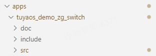
In Visual Studio Code, open the product development kit, expand
software/TuyaOS/appson the left, and find theprojectfolder of this demo.
-
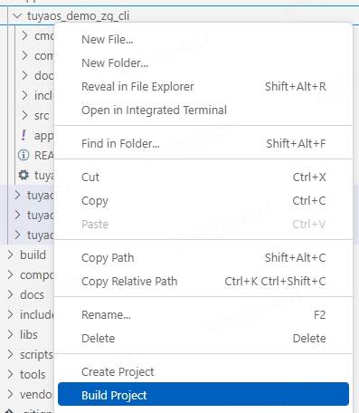
Right-click the product folder, and select Build Project. In the pop-up text box, enter the version number of the firmware to build in the format of
x.x.x. Press Enter.For the Telink chip platform, it is recommended to click Clean Project before clicking Build Project.


-
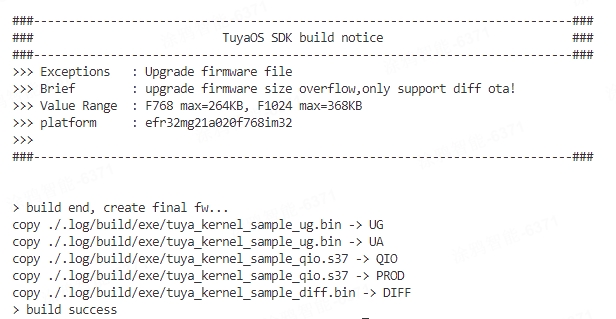
After the build succeeds, the console output is as follows (taking the Silicon Labs platform as an example):

You can view the build artifacts of the Silicon Labs platform in the
software/TuyaOS/_outputfolder. QIO indicates the flashed firmware, and UG indicates the OTA update file. Details are as follows:
- The build artifacts of the Silicon Labs platform are in the
software/TuyaOS/_outputfolder. - The build artifacts of the Telink platform are in the
outputfolder under the project path. - The build artifacts of the Phyplus platform are in the
software/TuyaOS/_outputfolder.
- The build artifacts of the Silicon Labs platform are in the
-
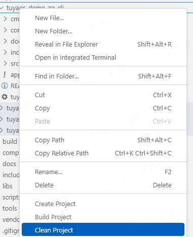
Clear the builhttps://images.tuyacn.com/fe-static/docs/img/734394c1-8bf8-4548-9f1a-61c0f87302d8 previous build. Right-click the product folder, select Clean Project, enter the version number, and press Enter.


Flash the firmware
- You can flash the Silicon Labs, Telink, and Phyplus platforms using tools from the chip vendors.
- For more information about the flashing tools from Tuya and Silicon Labs, see the Flash firmware and authorize chip section in Flash Firmware and Authorize Module.
Develop a routine
Configure basic information
Configure device registration
In the app_dev_register.c file within the src folder of the project, you can modify the device registration information, including device ID, cluster, and attribute.
To add or remove registered server clusters, modify the file content shown below.
// server cluster list
CONST TAL_CLUSTER_T onoff_1_ep_server_cluster_list[] = {
    DEF_CLUSTER_IDENTIFY_CLUSTER_ID(identify_attr_list)
    DEF_CLUSTER_GROUPS_CLUSTER_ID(group_attr_list)
    DEF_CLUSTER_SCENES_CLUSTER_ID(scene_attr_list)
    DEF_CLUSTER_ON_OFF_CLUSTER_ID(onoff_attr_list)
};
CONST TAL_CLUSTER_T onoff_2_ep_server_cluster_list[] = {

    DEF_CLUSTER_IDENTIFY_CLUSTER_ID(identify_attr_list)
    DEF_CLUSTER_GROUPS_CLUSTER_ID(group_attr_list)
    DEF_CLUSTER_SCENES_CLUSTER_ID(scene_attr_list)
    DEF_CLUSTER_ON_OFF_CLUSTER_ID(onoff_attr_list)
};
In the app_dev_register.h file within the include folder of the project, you can modify the registered endpoint and device ID by editing the file content shown below.
//Endpoint descriptor
TAL_ENDPOINT_T dev_endpoint_desc[] = {
    {ONOFF_1_ENDPOINT, ZHA_PROFILE_ID, ZG_DEVICE_ID_ON_OFF_LIGHT_SWITCH, ONOFF_1_EP_SERVER_CLUSTER_NUM, (TAL_CLUSTER_T *)&onoff_1_ep_server_cluster_list[0], 0, NULL},
    {ONOFF_2_ENDPOINT, ZHA_PROFILE_ID, ZG_DEVICE_ID_ON_OFF_LIGHT_SWITCH, ONOFF_2_EP_SERVER_CLUSTER_NUM, (TAL_CLUSTER_T *)&onoff_2_ep_server_cluster_list[0], 0, NULL},
};
Modify firmware information
In the app_config.yaml file within the project folder, you can configure information such as PID, model ID, and device type in two modes. Choose the one that suits your needs. The content and function of the file are as follows:
#######################################################################
# COMPATIBILITY of 【Tuya mode】
# For the use of tuya redefined attributes:
# [cluster:0x0000,attribute:0x0004] tuya manu name
# [cluster:0x0000,attribute:0x0005] tuya model id
########################################################################
Firmware_Information:
  description: "this is a demo project"
  device_role: "router"   # router/sleep_end_dev
  image_type: 0x1602
  manufacture_id: 0x1002
  model_id: "TS0002"
  manufacture_name: "_TZ3000_qlizmo9x" # capacity+pid
  module_name: ""
  chip_id: "" # efr32mg21a020f1024im32/efr32mg21a020f768im32/TLSR8258F1KET

########################################################################
# COMPATIBILITY of 【zigbee standard mode】
# For the use of ZCL standard attributes:
# [cluster:0x0000,attribute:0x0004] ManufacturerName
# [cluster:0x0000,attribute:0x0005] ModelIdentifier
########################################################################
# Firmware_Information:
#   description: "this is a demo project"
#   device_role: "router"   # router/sleep_end_dev
#   image_type: 0x1602
#   manufacture_id: 0x1002
#   model_id: "custom"
#   manufacture_name: "custom"
#   product_id: "bhzkbugw"
#   capacity: "_TZ3210_"
#   product_type: "TS0502B"
#   module_name: "ZSU"
#   chip_id: "efr32mg21a020f1024im32" # efr32mg21a020f1024im32/efr32mg21a020f768im32
To customize the model_id and manufacture_name attributes, you must use the second mode and specify the capacity, product_type, and product_id fields.
| Name | Function |
|---|---|
| description | The product description. |
| device_role | The device role, with router for a standard power router device and sleep_end_dev for a low power end device. Be cautious when making changes. |
| image_type | The firmware information, used to verify OTA updates. |
| manufacture_id | The manufacturer ID, used to verify OTA updates. |
| model_id | The device model, used to identify features after the device connects to a Tuya-enabled gateway. Be cautious when making changes. |
| manufacture_name | A value that combines the product capability value and Tuya’s PID, separated by an underscore (_), for example, _TZ3000_qlizmo9x. |
| module_name | The module model, indicating which module the product uses. |
| chip_id | The chip model, indicating which chip the product uses. Do not change this field. |
| capacity | The capability value of a Tuya-enabled product. Do not change this field. If you need to change it, contact the product manager. |
| product_type | The device model, used to identify features after the device connects to a Tuya-enabled gateway. Be cautious when making changes. |
| product_id | The product ID (PID) assigned by Tuya. Leave it empty. A new PID will be written during flashing and authorization. |
Configure device information
Routine development requires device information. You can configure it as follows:
Configure device information
In the switch_app_config.h file within the include folder of the project, you can modify the following component parameters:
| Parameter | Function |
|---|---|
| ONOFF_1_ENDPOINT | The default endpoint number for switch 1. Do not modify it unless necessary. |
| ONOFF_2_ENDPOINT | The default endpoint number for switch 2. Do not modify it unless necessary. |
| APP_ZG_NODE_ROUTER | The device type (router). Do not modify it unless necessary. |
| ZIGBEE_JOIN_TIMEOUT_MS | The timeout for pairing, which defaults to 30 seconds. |
| ZCL_ID_ONOFF | The ZCL ID for reporting the value of the onoff attribute. |
| PRESS_JOIN_TIME_MS | The duration required to press and hold the network button to start pairing, which defaults to 3 seconds. |
Configure pins
Configure buttons
In the switch_app_config.h file within the include folder of the project, you can modify the component parameters. To configure I/O port, active level, and interrupt mode for a button, modify the file content shown below:
//key info
#if defined(PHY622X_EVB)
#define KEY_STA_1_PIN               TUYA_GPIO_NUM_32
#elif defined(MCU_CORE_8258)
#define KEY_STA_1_PIN               TUYA_GPIO_NUM_26
#else
#define KEY_STA_1_PIN               TUYA_GPIO_NUM_0
#endif
#define KEY_STA_1_ACTIVE_LEVEL      TUYA_GPIO_LEVEL_LOW
#define KEY_STA_1_IRQ_MODE          TUYA_GPIO_IRQ_RISE_FALL

#if defined(PHY622X_EVB)
#define KEY_STA_2_PIN               TUYA_GPIO_NUM_33
#elif defined(MCU_CORE_8258)
#define KEY_STA_2_PIN               TUYA_GPIO_NUM_12
#else
#define KEY_STA_2_PIN               TUYA_GPIO_NUM_3
#endif
#define KEY_STA_2_ACTIVE_LEVEL      TUYA_GPIO_LEVEL_LOW
#define KEY_STA_2_IRQ_MODE          TUYA_GPIO_IRQ_RISE_FALL

#if defined(PHY622X_EVB)
#define KEY_NWK_PIN                 TUYA_GPIO_NUM_34
#elif defined(MCU_CORE_8258)
#define KEY_NWK_PIN                 TUYA_GPIO_NUM_13
#else
#define KEY_NWK_PIN                 TUYA_GPIO_NUM_4
#endif
#define KEY_NWK_ACTIVE_LEVEL        TUYA_GPIO_LEVEL_LOW
#define KEY_NWK_IRQ_MODE            TUYA_GPIO_IRQ_RISE_FALL
Configure indicators
In the switch_app_config.h file within the include folder of the project, you can modify the component parameters. To configure I/O port, active level, and initial state for an indicator, modify the file content shown below:
//led info
#if defined(PHY622X_EVB)
#define LED_STA_1_PIN               TUYA_GPIO_NUM_31
#elif defined(MCU_CORE_8258)
#define LED_STA_1_PIN               TUYA_GPIO_NUM_18
#else
#define LED_STA_1_PIN               TUYA_GPIO_NUM_7
#endif
#define LED_STA_1_ACTIVE_LEVEL      TUYA_GPIO_LEVEL_LOW
#define LED_STA_1_INIT_STATUS       LED_ST_OFF              //OFF

#if defined(PHY622X_EVB)
#define LED_STA_2_PIN               TUYA_GPIO_NUM_26
#elif defined(MCU_CORE_8258)
#define LED_STA_2_PIN               TUYA_GPIO_NUM_1
#else
#define LED_STA_2_PIN               TUYA_GPIO_NUM_8
#endif
#define LED_STA_2_ACTIVE_LEVEL      TUYA_GPIO_LEVEL_LOW
#define LED_STA_2_INIT_STATUS       LED_ST_OFF              //OFF

#if defined(PHY622X_EVB)
#define LED_NWK_PIN                 TUYA_GPIO_NUM_11
#elif defined(MCU_CORE_8258)
#define LED_NWK_PIN                 TUYA_GPIO_NUM_0
#else
#define LED_NWK_PIN                 TUYA_GPIO_NUM_19
#endif
#define LED_NWK_ACTIVE_LEVEL        TUYA_GPIO_LEVEL_LOW
#define LED_NWK_INIT_STATUS         LED_ST_OFF              //OFF
The mapping of pins varies depending on platforms.
- For the Silicon Labs and Telink platforms, you can view it in the
tkl_platform_types.hfile. - For the Phyplus platform, see ZPU Module Datasheet.
The following displays how the pins of Silicon Labs MG21 are mapped, where TUYA_GPIO_NUM_0 corresponds to PA0.
//GPIO Index
#define APP_GPIO_PA0    TUYA_GPIO_NUM_0
#define APP_GPIO_PA1    TUYA_GPIO_NUM_1
#define APP_GPIO_PA2    TUYA_GPIO_NUM_2
#define APP_GPIO_PA3    TUYA_GPIO_NUM_3
#define APP_GPIO_PA4    TUYA_GPIO_NUM_4
#define APP_GPIO_PA5    TUYA_GPIO_NUM_5
#define APP_GPIO_PA6    TUYA_GPIO_NUM_6
#define APP_GPIO_PB0    TUYA_GPIO_NUM_7
#define APP_GPIO_PB1    TUYA_GPIO_NUM_8
#define APP_GPIO_PC0    TUYA_GPIO_NUM_9
#define APP_GPIO_PC1    TUYA_GPIO_NUM_10
#define APP_GPIO_PC2    TUYA_GPIO_NUM_11
#define APP_GPIO_PC3    TUYA_GPIO_NUM_12
#define APP_GPIO_PC4    TUYA_GPIO_NUM_13
#define APP_GPIO_PC5    TUYA_GPIO_NUM_14
#define APP_GPIO_PD0    TUYA_GPIO_NUM_15
#define APP_GPIO_PD1    TUYA_GPIO_NUM_16
#define APP_GPIO_PD2    TUYA_GPIO_NUM_17
#define APP_GPIO_PD3    TUYA_GPIO_NUM_18
#define APP_GPIO_PD4    TUYA_GPIO_NUM_19
Support and help
If you have any problems with TuyaOS development, you can post your questions in the Tuya Developer Forum.
Is this page helpful?
YesFeedbackIs this page helpful?
YesFeedback


