Troubleshooting and FAQs
Troubleshooting
Process
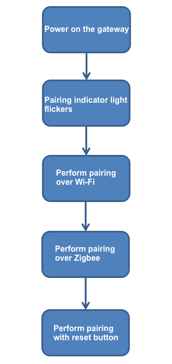
Gateway power-on
-
Check whether the circuits and components are well soldered.
-
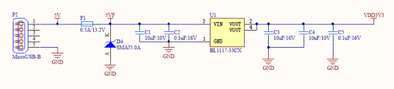
Check the USB 5V and LDO 3.3V voltage with an oscilloscope. The following requirements must be met:
Parameter Acceptable result 5V 4.6V to 5.5V 3.3V 3.0V to 3.6V
Indicator light
-
Check whether the circuits and components are well soldered.
-
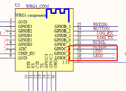
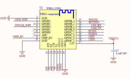
Use an oscilloscope to check whether pin 18 (
GPIOC_1) and pin 19 (GPIOC_0) of the Wi-Fi module are at a high level.
Wi-Fi pairing
-
Check whether the circuits and components are well soldered.
-
Use DC 3.3V power supply to check whether the module current works properly.
Parameter Acceptable result Current for pairing <200 mA Maximum current <350 mA
Zigbee pairing
-
Check whether the circuits and components are well soldered.
-
Use DC 3.3V power supply to check whether the module current works properly.
Parameter Acceptable result Current for pairing <50 mA Maximum current <150 mA
Button
-
Check whether the circuits and components are well soldered.
-
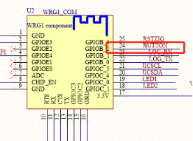
Use an oscilloscope to check whether pin 24 (
GPIOB_2) of the Wi-Fi module is at a low level when the button is pressed.
Failed to enter the pairing mode
Hardware
-
After power on, the light is off or in a wrong status.
- Make sure the module pins are connected properly, which is consistent with the configuration of the platform or the custom firmware.
- Make sure the power supply of the module works properly, the voltage is between 3V and 3.6V, and the power supply ripple is less than the 100 mV reference range. The reference circuit design of the module must be followed. Taking TYWE3L for example, enable the EN pin pull-up resistor, and make sure the voltage is no less than 2.5V.
- Make sure the supply current of the module is normal. Taking TYWE3S for example, the module needs about 100 mA of current when it is working properly. During pairing, the current will be more than 450 mA for a few microseconds.
- Make sure the module pins are in a normal state. Take TYWE3S for example, the GPIO1 (
TX), GPIO0, and GPIO15 pins affect the startup of the module. For power on, GPIO1 (TX) and GPIO0 must be at a high level, and GPIO15 must be at a low level. The level of these pins must meet the requirements when they are powered on, free from disturbance. - When the lights turn on in a cyclical, breathing, dim, or colored way, check whether there is a production test router in the test environment. If the indicators are dimly on, troubleshoot the circuit problems too.
- Check whether the firmware is downloaded or whether the firmware flashing is correct. Use the USB-to-TTL converter to monitor the Wi-Fi module log during the entire pairing process and find out the reasons. Taking TYWE3L for example, connect the RX pin of a serial port tool to the printing port
TXof the module, connect GND to GND, and then set 74880 as the baud rate.
-
The lights are in an expected state after power on, but cannot enter the pairing state after reset.
- During the on/off and reset process, the single power-on time of a light does not exceed 5 seconds. For example, the light is turned on and off consecutively three times within 15 seconds. The output electrolytic capacitor of some module circuits is large, so the circuit might not be fully discharged before being powered on again. To ensure a full discharge, the light must stay off for a longer time before the test.
- Some devices, such as strip lights and desk lamps, enter the pairing state after the reset button is pressed. Use an oscilloscope to monitor whether the trigger signal from the button to the module works properly. During the circuit design, the button requires filtering processing.
- After the above points are proven to be working properly, use the USB-to-TTL converter to monitor the Wi-Fi module log during the entire pairing process and find out the reasons. Taking TYWE3L for example, connect the RX pin of a serial port tool to the printing port
TXof the module, connect GND to GND, and then set 74880 as the baud rate.
Mobile app
Everything goes on well after power on, and the indicator light can flicker quickly or slowly.
- Check whether the Wi-Fi password is correct.
- Check whether the Wi-Fi network is 2.4 GHz.
FAQs
The gateway cannot be powered on. Why?
- Check whether the 5V power input and USB connector work properly.
- Check whether the internal 3.3V power output works properly.
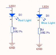
The indicator does not turn on. Why?
Check whether the LED and voltage divider resistors R3 and R4 are well soldered.
Pairing over a Zigbee network failed. Why?
- Check whether the gateway can be paired over a Wi-Fi network.
- Check whether the Zigbee module is soldered well.
- Use a 3.3V regulated power supply to supply power to the Zigbee module, and check whether the working current of the Zigbee module is normal.
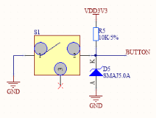
The reset button does not work. Why?
- Check whether the reset button is soldered well.
- Check whether the electrostatic protection devices work properly.
Is this page helpful?
YesFeedbackIs this page helpful?
YesFeedback


