Energy Metering
This topic describes the common questions about the energy metering feature to help you troubleshoot problems.
What types of chips can be used for energy metering?
- Pulse counting: The Wi-Fi module calculates the pulse counts and frequencies and converts them into the power reading. HLW8012 and BL0937 use this method.
- Serial communication: The Wi-Fi module receives the data from the energy metering chip through the serial port and converts it to the power reading. HLW8032 and BL0942 use this method.
What is the accuracy of the power reading?
- Serial communication (BL0942 or HLW8032): 3%
- Pulse counting (BL0937 or HLW8012): 5%
How to set parameters for the energy metering in firmware configuration?
Take care of the parameters of over-voltage, under-voltage, and over-current, which defaults to 0. You can set them based on your application or leave them as is.
- Over-current: If the measured current exceeds the threshold, the relay will trip and the fault reporting will be triggered.
- Under-voltage: If the measured voltage falls below the threshold, the relay will trip and the fault reporting will be triggered.
- Over-voltage: If the measured voltage exceeds the threshold, the relay will trip and the fault reporting will be triggered.
How can I choose an appropriate shunt resistor for the BL0937 or HLW8012 chip?
The selection of a shunt resistor depends on the current flowing through it. The maximum voltage across the current shunt is 50 mV. If you need a maximum current of 20A, the resistor must be less than 2.5 mΩ (50 mV/20A). Otherwise, the calibration might not be accurate.
Why don’t you provide options for resistors and pins in firmware configuration for the BL0942 or HLW8032 chip?
These two chips use serial communication to send the acquired electricity data to Tuya’s modules. The resistor is set to the default 1 mΩ.
Why does the calibration of energy metering fail?
Is the calibration process correct?
After the device is powered on, the relay will close its contact. The Wi-Fi status indicator will blink slowly twice every three seconds. If your device failed to act as above mentioned, it indicates the calibration failed. For more information about the calibration, see Production Test on Energy Monitoring Socket. If your device behaves as expected, it will enter the metering calibration as it is connected to the designated router.
Is the load for testing appropriate?
Select a resistor based on the voltage of your device. For a 220V device, use a 100W 560Ω ceramic resistor with 1% tolerance. For a 120V device, use a 200W 144Ω ceramic resistor with 1% tolerance. Connect the resistor to the input live and input neutral terminals.
Does the operating voltage match the calibration voltage?
- Parameters for 220V regulated power supply: 220V±3V, 392 mA±15 mA, 87W±2W
- Parameters for 120V regulated power supply: 120V±2V, 833 mA±15 mA, 100W±2W
Does the hardware work correctly?
Relay
Check if the relay closes its contact after the device is powered on.
Sampling circuit
Check if you use the right shunt resistor (1 mΩ or 2 mΩ) or if there are issues with wiring.
Power supply to the module
Check if the module is supplied with 3.3V. If the power supply works fine, there might be a problem with the module itself. Try another module and test again.
Power supply to the sampling chip
HLW8012 and HLW8032 use a 5V supply. BL0937 and BL0942 use 3.3V supply. If you use transistor-transistor logic (TTL), make sure you supply the correct power to your chip.
Why doesn’t the Tuya Developer Platform show the complete updated metering data?
When the voltage, current, and power are reported at the same time, the device will filter the data to report and remove those identical to the data reported last time.
Example:
Assume that 220.0V, 1,000 mA, 220.0W has been reported, and 220V, 1,500 mA, 330.0W is to be reported. We can see that the voltage is not changed so the device only reports the latest value of power and current.
Why doesn’t voltage times current equal the expected power?
Data out of sync
The chip acquires energy data at a regular interval. For BL0937 and HLW8032 chips, since a single pin is used to acquire both voltage and current, the complete acquisition duration is 11s (1s for voltage and 10s for current). The electricity data is updated two seconds after the pin function is switched from voltage to current. Before an acquisition interval (11s) is about to be completed, the voltage is not updated and the current is updated every one second and power every two seconds.
Small power factor
Check if you are using non-resistive loads. This can cause the power factor to be small.
Small power
The level of signal produced by the shunt resistor is 10 µV. Incorrect wiring and signal interference can affect the performance of signal sampling. For more information, see Energy Metering Hardware Design Guideline.
Why is the error of energy data acquisition large?
Did you perform calibration?
After your device is connected to the cloud, you can check the calibration parameter and the test result by device ID.
If the test result is 1, it indicates the calibration is successful. Other values indicate calibration failed.
Compare the obtained calibration parameter with the reference parameter. The voltage divider ratio and shunt resistor are the optional upper limit value. A larger current can cause larger errors for small power loads.
Select peripherals
| Hardware (pull-down) | Input current (Max) | Input voltage (Max) | Max current (Valid value) | 1.2 times the maximum input voltage | Voltage divider ratio | Shunt resistor (mΩ) |
|---|---|---|---|---|---|---|
| HLW8012 | 30.9 | 495 | 60 | 264 | 0.00188 | 0.515 |
Calculate the maximum pulse frequency
| Hardware (pull-down) | Input current (Max) | Input voltage (Max) | Power factor | Voltage factor | Current factor | F (Power) Hz | F (Voltage) Hz | F (Current) Hz |
|---|---|---|---|---|---|---|---|---|
| BL0937 | 50 | 200 | 1160417 | 12641 | 77699 | 11604 | 2528 | 3885 |
Did you use the reference circuit?
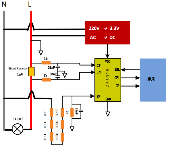
Reference circuit for BL0937
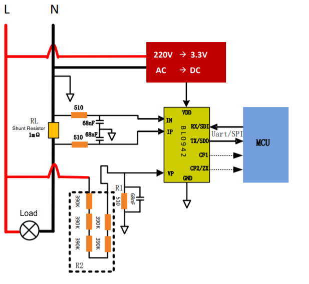
Reference circuit for BL0942
Is the tolerance of your shunt resistor 1%?
Make sure to use a shunt resistor with a tolerance of no more than 1%.
Did you correctly perform the calibration?
If you did not perform calibration under the nominal voltage or did not use the right shunt resistor, errors will be present in calibration data. For more information about calibration, see Production Test on Energy Monitoring Socket.
Are the errors present in measurement values?
The possible reasons are incorrect measurement method settings on software or failed calibration.
Why is the displayed current reading on the app zero even if the load is operating?
Did you use a small power load?
-
For BL0937 or HLW8012, if the measured power is less than 3W, the power and current values will be zeroed out.
-
For BL0942 or HLW8032, if the measured power is less than 2W, the power and current values will be zeroed out.
What are the production test factor and the production test result used for?
Production test factor
It is used to calculate the actual energy consumption data. The factors vary depending on the chip models. BL0942 is calibration-free so the factor is not needed.
Production test result
It shows you the result of calibration. 1 indicates calibration is successful. Other values indicate calibration failed.
How is the reference energy consumption calculated?
Calculation method for HLW8012 and HLW8032
| Power | CF frequency (f) | CF output cycle (t) | 1 kWh | 0.001 kWh | The number of CFs for 1 kWh | The number of CFs for 0.001 kWh |
|---|---|---|---|---|---|---|
| 1000W | a | 1/a | 1,000W × h | (1,000W × h)/1,000 | a × 3,600s | (a × 3,600)/1,000 |
| 1W | b | 1/b | 1W × h × 1,000 | 1W × h | b × 3,600s × 1,000h | b × 3,600 |
| P (Calibration power) | c | 1/c |
- The input power is directly proportional to the frequency of the output CF so we can get
1/b = P/candb = c/P. - With the information from the above table, we calculate the number of CF pulses of 0.001 kWh by
b × 3,600. - We calculate the number of CF pulses of 0.01 kWh by
b × 3,600 = (c/P) × 3,600. - The MCU measures the cycle of the input load P. Assume that the cycle of the corresponding frequency
cisT. We can get0.001 kWh = b × 3,600 = (1/(P × T)) × 3,600.
What frequency relationship does the energy metering chip have?
Frequency table for HLW8012 and HLW8032
220V AC input power, 2 mΩ shunt resistor
| Power (W) | Voltage (V) | Current (A) = P/V | Resistor voltage divider (K) = 470K × 4 | Resistor voltage divider factor = 1K/(470K × 4) | Shunt resistor ® | Input voltage (V) | Input current (V) = I × R | F (Power) Hz | F (Voltage) Hz | F (Current) Hz |
|---|---|---|---|---|---|---|---|---|---|---|
| 3600 | 220 | 16.364 | 1880 | 0.000531915 | 0.002 | 0.117 | 0.032727273 | 870.47 | 673.26 | 2259.47 |
| 3000 | 220 | 13.636 | 1880 | 0.000531915 | 0.002 | 0.117 | 0.027272727 | 725.39 | 673.26 | 1882.89 |
| 2000 | 220 | 9.091 | 1880 | 0.000531915 | 0.002 | 0.117 | 0.018181818 | 483.60 | 673.26 | 1255.26 |
| 1000 | 220 | 4.545 | 1880 | 0.000531915 | 0.002 | 0.117 | 0.009090909 | 241.80 | 673.26 | 627.63 |
| 500 | 220 | 2.273 | 1880 | 0.000531915 | 0.002 | 0.117 | 0.004545455 | 120.90 | 673.26 | 313.82 |
| 200 | 220 | 0.909 | 1880 | 0.000531915 | 0.002 | 0.117 | 0.001818182 | 48.36 | 673.26 | 125.53 |
| 100 | 220 | 0.455 | 1880 | 0.000531915 | 0.002 | 0.117 | 0.000909091 | 24.18 | 673.26 | 62.76 |
| 50 | 220 | 0.227 | 1880 | 0.000531915 | 0.002 | 0.117 | 0.000454545 | 12.09 | 673.26 | 31.38 |
| 20 | 220 | 0.091 | 1880 | 0.000531915 | 0.002 | 0.117 | 0.000181818 | 4.84 | 673.26 | 12.55 |
| 10 | 220 | 0.045 | 1880 | 0.000531915 | 0.002 | 0.117 | 9.09091E-05 | 2.42 | 673.26 | 6.28 |
| 5 | 220 | 0.023 | 1880 | 0.000531915 | 0.002 | 0.117 | 4.54545E-05 | 1.21 | 673.26 | 3.14 |
| 2 | 220 | 0.009 | 1880 | 0.000531915 | 0.002 | 0.117 | 1.81818E-05 | 0.48 | 673.26 | 1.26 |
| 1 | 220 | 0.005 | 1880 | 0.000531915 | 0.002 | 0.117 | 9.09091E-06 | 0.24 | 673.26 | 0.63 |
| 0.8 | 220 | 0.004 | 1880 | 0.000531915 | 0.002 | 0.117 | 7.27273E-06 | 0.19 | 673.26 | 0.50 |
110V AC input power, 1 mΩ shunt resistor
| Power (W) | Voltage (V) | Current (A) = P/V | Resistor voltage divider (K) = 470K × 4 | Resistor voltage divider factor = 1K/(470K × 4) | Shunt resistor ® | Input voltage (V) | Input current (V) = I × R | F (Power) Hz | F (Voltage) Hz | F (Current) Hz |
|---|---|---|---|---|---|---|---|---|---|---|
| 3600 | 110 | 32.727 | 1880 | 0.000531915 | 0.001 | 0.059 | 0.032727273 | 435.24 | 336.63 | 2259.47 |
| 3000 | 110 | 27.273 | 1880 | 0.000531915 | 0.001 | 0.059 | 0.027272727 | 362.70 | 336.63 | 1882.89 |
| 2000 | 110 | 18.182 | 1880 | 0.000531915 | 0.001 | 0.059 | 0.018181818 | 241.80 | 336.63 | 1255.26 |
| 1000 | 110 | 9.091 | 1880 | 0.000531915 | 0.001 | 0.059 | 0.009090909 | 120.90 | 336.63 | 627.63 |
| 500 | 110 | 4.545 | 1880 | 0.000531915 | 0.001 | 0.059 | 0.004545455 | 60.45 | 336.63 | 313.82 |
| 200 | 110 | 1.818 | 1880 | 0.000531915 | 0.001 | 0.059 | 0.001818182 | 24.18 | 336.63 | 125.53 |
| 100 | 110 | 0.909 | 1880 | 0.000531915 | 0.001 | 0.059 | 0.000909091 | 12.09 | 336.63 | 62.76 |
| 50 | 110 | 0.455 | 1880 | 0.000531915 | 0.001 | 0.059 | 0.000454545 | 6.04 | 336.63 | 31.38 |
| 20 | 110 | 0.182 | 1880 | 0.000531915 | 0.001 | 0.059 | 0.000181818 | 2.42 | 336.63 | 12.55 |
| 10 | 110 | 0.091 | 1880 | 0.000531915 | 0.001 | 0.059 | 9.09091E-05 | 1.21 | 336.63 | 6.28 |
| 5 | 110 | 0.045 | 1880 | 0.000531915 | 0.001 | 0.059 | 4.54545E-05 | 0.60 | 336.63 | 3.14 |
| 2 | 110 | 0.018 | 1880 | 0.000531915 | 0.001 | 0.059 | 1.81818E-05 | 0.24 | 336.63 | 1.26 |
| 1 | 110 | 0.009 | 1880 | 0.000531915 | 0.001 | 0.059 | 9.09091E-06 | 0.12 | 336.63 | 0.63 |
| 0.8 | 110 | 0.007 | 1880 | 0.000531915 | 0.001 | 0.059 | 7.27273E-06 | 0.10 | 336.63 | 0.50 |
- The output frequency of power, voltage, and current is the reference value calculated according to the formula provided by the HLW8012 user guide. The actual values can vary depending on the sample circuit.
- HLW8012 voltage input signal:
V = 220V × (1K/(470K × 4)). - HLW8012 current input signal:
V = I (current) × R (shunt resistor). TheRcan be 0.001Ω, 0.002Ω, or 0.005Ω. - The power is linearly proportional to the output frequency.
Is this page helpful?
YesFeedbackIs this page helpful?
YesFeedback


