Bluetooth LE–nRF52832
Last Updated on : 2025-09-23 09:58:18download
This topic describes the basics of the chip platform used in TuyaOS development. For more information, visit Tuya Developer Forum.
Hardware environment
Datasheet
-
The datasheet can be found in
hardware\nRF52832\chip_manual\nRF52832_PS_v1.7.pdf. -
Alternatively, check the Nordic Semiconductor website for the latest information.
Development board
-
You can purchase the nRF52832 Bluetooth development board (part number: 2.03.99.00045) from the Tuya Developer Platform. This board uses Tuya’s Bluetooth LE dongle hardware.
Schematic diagram of the dongle: Click to download.
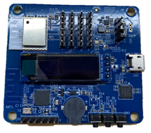
-
Alternatively, use Nordic development board and check the official documentation.
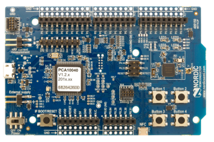
Peripherals
UART
This platform has one UART, used for authorization and debugging.
| UART | Feature | Pin |
|---|---|---|
| UART 0 | TX | P0.06 |
| UART 0 | RX | P0.08 |
SPI
When multiple peripherals use the same register address, only one of them can be used at a time. The SPI supports SPI1 and SPI2.

| SPI | Feature | Pin |
|---|---|---|
| SPI1 | CS | P0.05 |
| SPI1 | CLK | P0.04 |
| SPI1 | SDI | P0.02 |
| SPI1 | SDO | P0.03 |
| SPI2 | CS | P0.28 |
| SPI2 | CLK | P0.29 |
| SPI2 | SDI | P0.30 |
| SPI2 | SDO | P0.31 |
I2C
When multiple peripherals use the same register address, only one of them can be used at a time. The I2C supports I2C0.

| I2C | Feature | Pin |
|---|---|---|
| I2C0 | SCL | P0.16 |
| I2C0 | SDA | P0.15 |
PWM
| Channel | Pin |
|---|---|
| 0 | P0.28 |
| 1 | P0.29 |
| 2 | P0.30 |
| 3 | P0.31 |
ADC
| Channel | Pin |
|---|---|
| 0 | P0.02 |
| 1 | P0.03 |
| 2 | P0.04 |
| 3 | P0.05 |
| 4 | P0.28 |
| 5 | P0.29 |
| 6 | P0.30 |
| 7 | P0.31 |
Key control
P0.14
- Press the button to wake up the device.
- Press and hold the button for three seconds to factory reset the device.
Startup time detection pin
P0.05
Set this pin to high after entering the main function.
Software environment
Install Keil and nRF52832-dependent environment.
Keil
-
Download Keil from the Arm Keil website. mdk528a.exe is recommended. During installation, keep all the default settings.
-
If you are prompted to install a driver, continue with Install.
-
When opening Keil, if you are prompted to install a software pack, close the window.
-
After Keil is installed, add the path of the
UV4.exefile to the environment variable. For example:TUYAOS_COMPILE_TOOL:C:\Keil_v5\UV4, as shown below.
nRF Command Line Tools
nRF Command Line Tools contain J-Link software and Nordic Semiconductor’s command-line tools, such as J-Link drivers, nrfjprog executable, nrfutil, and mergehex executable.
The steps to install nRF Command Line Tools are as follows, taking Windows as an example.
-
Download nRF Command Line Tools from Nordic Semiconductor.
-
Choose platform and version. For example, the installer for Win32 can be
nRF5x-Command-Line-Tools_9_8_1_Installer.exe.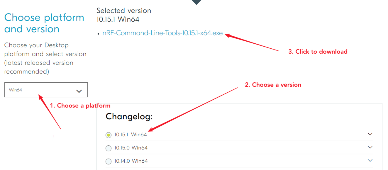
-
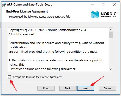
Double-click the
.exefile and accept the license agreement to install. During installation, keep all the default options.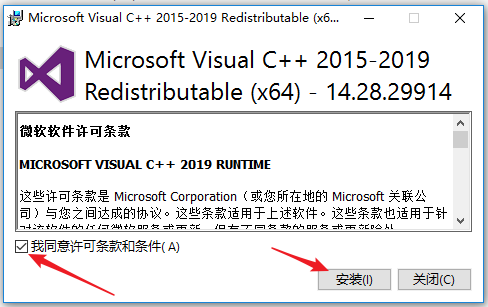
-
When you get the following screen, make sure to check
select all.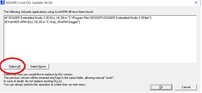
Arm’s CMSIS
- Click to download Arm’s CMSIS.
- Follow the prompts to complete the installation.
Device Family Pack
-
Follow the prompts to complete the installation.
Do not let Keil automatically download Device Family Pack. Otherwise, the compilation might fail.
J-Link
-
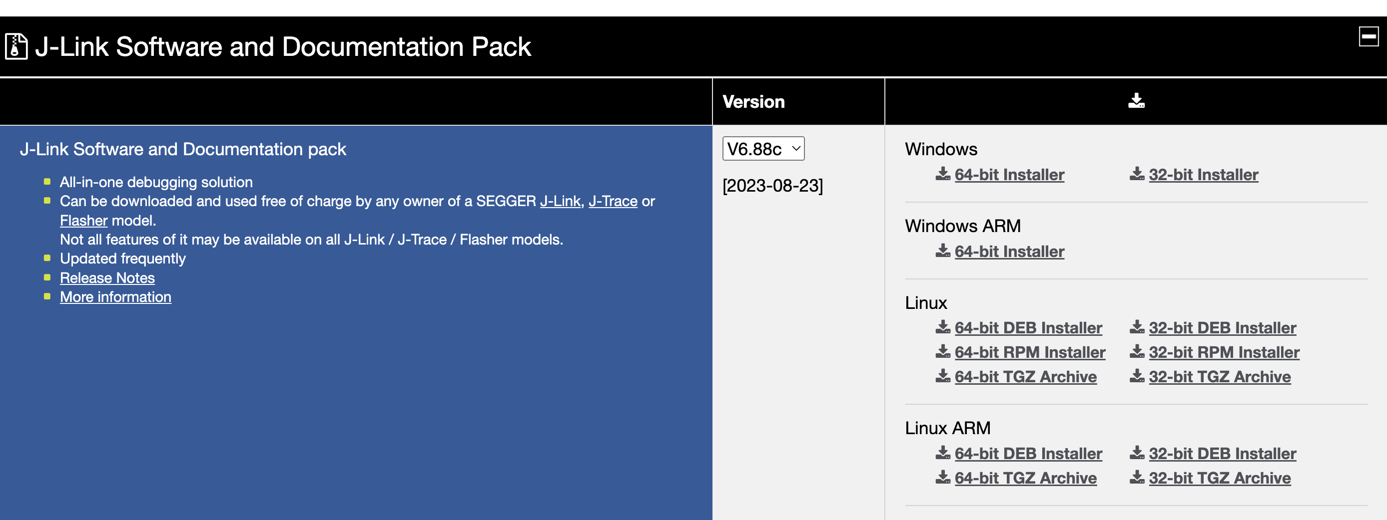
Download J-Link from Segger.
-
Choose the appropriate version (V6.88c is used for testing) and follow the prompts to complete the installation.
VSCode development
This platform supports both the Visual Studio Code development environment provided by Tuya and the Keil development environment provided by the chip original manufacturer.
For detailed instructions on using the Visual Studio Code development environment, please refer to the chapters Get development framework and Build development framework.
Develop software
Enable scanning

#define TKL_BLUETOOTH_SUPPORT_SCAN (1)
Flash and RAM footprint
-
Disable the testing feature.
#define TUYA_SDK_TEST 0 -
Disable Tuya logging.
#define ENABLE_LOG 0 #define BOARD_ENABLE_LOG 0 -
Disable chip vendor logging.

-
Disable scanning.
#define TKL_BLUETOOTH_SUPPORT_SCAN (0) -
After a full compilation of the whole project, open the
.mapfile. You will get the RAM and flash footprint.
About 10 KB data of RW is actually stored in flash, so the actual used RAM is about 26 KB, as shown below.

When you enable scanning
#define TKL_BLUETOOTH_SUPPORT_SCAN (1)After a full compilation of the whole project, open the
.mapfile. You will get the RAM and flash footprint.
Firmware flashing
Wire connection
Select SW mode in J-Link and connect J-Link and the device as described below.
| J-Link | Device |
|---|---|
| VCC | VCC |
| GND | GND |
| DIO | DIO |
| CLK | CLK |
Firmware description

Flashing method 1
-
In Visual Studio Code, right-click
apps\tuyaos_demo_ble_peripheralin the Explorer and choose Reveal in File Explorer.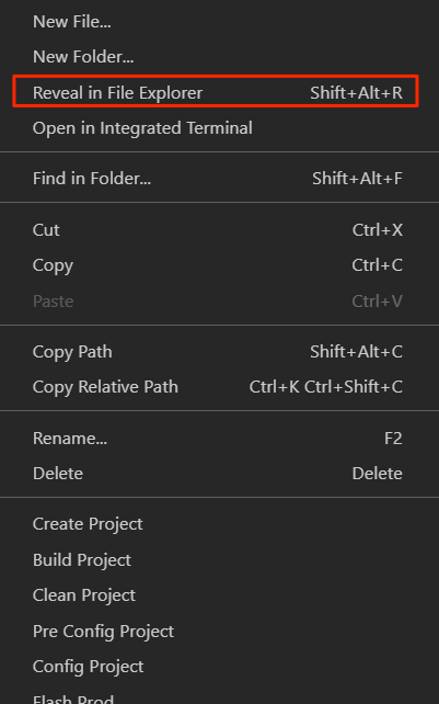
-
Open
tuyaos_demo_ble_peripheral\_build\hex. -
Double-click
load_softdevice_bootloader_app.batto flash firmware.The full firmware will be flashed to the device. After the firmware is flashed, you need to perform authorization.
Flashing method 2
Flash firmware to the device by using Download in Keil. Only the application-level code can be flashed.
Flashing method 3
Use J-Flash to flash firmware. You may need to learn how to use J-Flash by yourself.
Flashing method 4
Use nRF Connect for Desktop to flash firmware.
Features
Startup time
-
Use a logic analyzer to measure the signal time difference between the VCC pin and the startup time detection pin.
-
Detection pins: peripheral → startup time detection pin

Flash partition
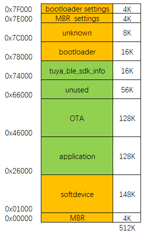
Adjust flash partitions
In the original project, you can modify the following macros to adjust the default flash partitions.
// Flash
#ifndef BOARD_FLASH_BULK_DATA_START_ADDR
#define BOARD_FLASH_BULK_DATA_START_ADDR        (0x70000)
#endif

#ifndef BOARD_FLASH_TUYA_INFO_START_ADDR
#define BOARD_FLASH_TUYA_INFO_START_ADDR        (0x74000)
#endif

// #ifndef BOARD_FLASH_OTA_INFO_ADDR
// #define BOARD_FLASH_OTA_INFO_ADDR               (0x7C000)
// #endif

#ifndef BOARD_FLASH_OTA_START_ADDR
#define BOARD_FLASH_OTA_START_ADDR              (0x46000)
#endif

#ifndef BOARD_FLASH_OTA_END_ADDR
#define BOARD_FLASH_OTA_END_ADDR                (0x66000)
#endif

#ifndef BOARD_FLASH_OTA_SIZE
#define BOARD_FLASH_OTA_SIZE                    (BOARD_FLASH_OTA_END_ADDR - BOARD_FLASH_OTA_START_ADDR)
#endif

// #ifndef BOARD_FLASH_MAC_START_ADDR
// #define BOARD_FLASH_MAC_START_ADDR              (0)
// #endif
Power consumption
-
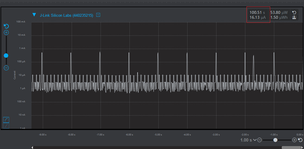
If the TuyaOS Bluetooth LE SDK enables the DCDC mode, the device can enter a lower power mode.
-
Not enabling DCDC mode can result in higher power consumption.Measure the average power consumption of typical one-second advertising.
Is this page helpful?
YesFeedbackIs this page helpful?
YesFeedback


