Bluetooth LE–PHY6222
This topic describes the basics of the chip platform used in TuyaOS development. For more information, visit Tuya Developer Forum.
Hardware environment
Datasheet
The datasheet can be found in hardware\PHY6222\chip_manual\PHY6222_BLE_SoC_Datasheet_v1.2_20210430.pdf.
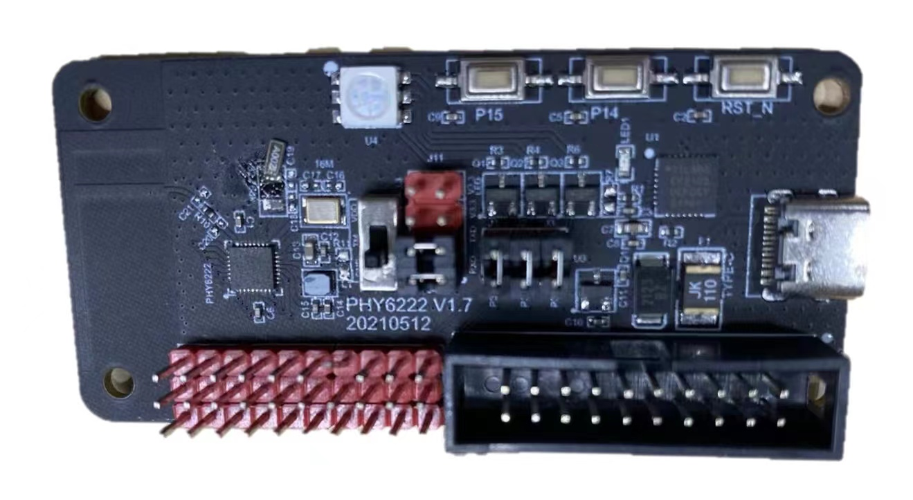
Development board
Phyplus official PHY6222 development board is used. You can purchase the board from Phyplus.
Peripherals
UART
This platform has two UARTs. UART0 is used for log output. UART1 is used for flashing, authorization, and debugging.
| UART | Feature | Pin | Remarks |
|---|---|---|---|
| UART0 | TX | P2 | Log |
| UART0 | RX | P0 | - |
| UART1 | TX | P9 | Flashing, authorization, and testing. |
| UART1 | RX | P10 | - |
SPI
This platform has two SPI buses.
| SPI | Feature | Pin |
|---|---|---|
| SPI0 | CS | P32 |
| SPI0 | CLK | P31 |
| SPI0 | SDI | P18 |
| SPI0 | SDO | P20 |
| SPI1 | CS | P14 |
| SPI1 | CLK | P15 |
| SPI1 | SDI | P33 |
| SPI1 | SDO | P34 |
I2C
This platform has two I2Cs. To display SDK information (TuyaOS demo), the OLED is pre-initialized. Therefore, only one I2C can be used for testing.
| I2C | Feature | Pin |
|---|---|---|
| I2C0 | SCL | P24 |
| I2C0 | SDA | P23 |
PWM
| Channel | Pin |
|---|---|
| 0 | P31 |
| 1 | P32 |
| 2 | P26 |
| 3 | P33 |
| 4 | P34 |
| 5 | P7 |
ADC
Only support 12-bit resolution.
Voltage value is returned.
| Channel | Pin |
|---|---|
| 0 | P11 |
| 1 | P23 |
| 2 | P24 |
| 3 | P14 |
| 4 | P15 |
| 5 | P20 |
Key control
P7
-
Press the button to wake up the device.
-
Press and hold the button for three seconds to factory reset the device.
Power-on detection pin
P1
Set this pin to high after entering the main function.
Software environment
Keil
-
Download Keil from the Arm Keil website. mdk528a.exe is recommended. During installation, keep all the default settings.
-
If you are prompted to install a driver, continue with Install.
-
When opening Keil, if you are prompted to install a software pack, close the window.
-
After Keil is installed, add the path of the
UV4.exefile to the environment variable. For example:TUYAOS_COMPILE_TOOL:C:\Keil_v5\UV4, as shown below.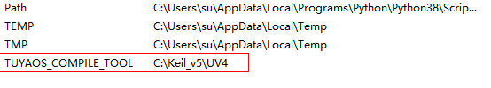
VSCode development
This platform supports both the Visual Studio Code development environment provided by Tuya and the Keil development environment provided by the chip original manufacturer.
For detailed instructions on using the Visual Studio Code development environment, please refer to the chapters Get development framework and Build development framework.
Develop software
Enable scanning
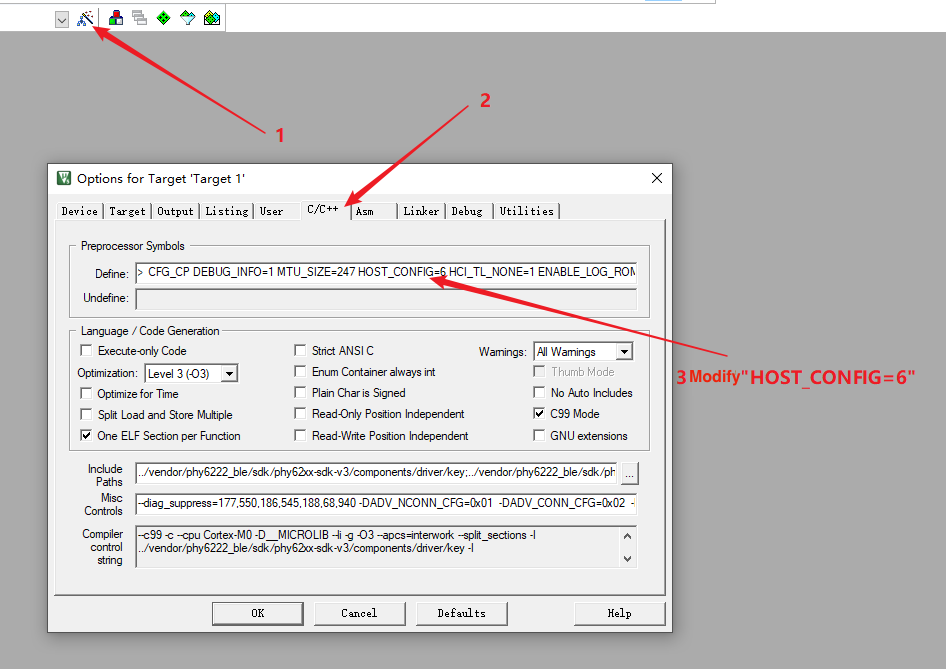
HOST_CONFIG=6
Flash and RAM footprint
-
Disable the testing feature.
#define TUYA_SDK_TEST 0 -
Disable logging.
#define ENABLE_LOG 0 #define BOARD_ENABLE_LOG 0 -
Disable scanning.
HOST_CONFIG=4 -
After a full compilation of the whole project, open the
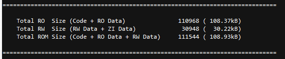
.mapfile. You will get the following screen.- The flash footprint:
- The RAM footprint:
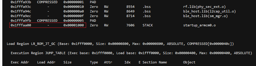
-
The free RAM:
- = 0x1fffffff − (0x1fffaa00 + 0x00001000)
- = 17919 bytes
- = 17.5 KB
When you enable scanning
HOST_CONFIG=6
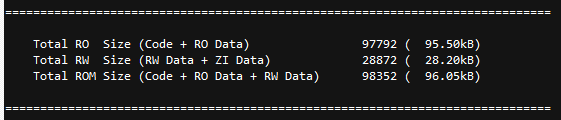
After a full compilation of the whole project, open the .map file. You will get the following screen.
-
The flash footprint:
-
The RAM footprint:
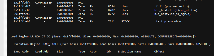
The free RAM:
- = 0x1fffffff − (0x1fffceb8 + 0x00001000)
- = 8519 bytes
- = 8.3 KB
Calculate free RAM
Some Phyplus code might be stored in RAM. Therefore, The free RAM we calculate may vary from the one provided in the .map file. Here is how to calculate the free RAM.
-
Open the
.mapfile. -
Find the
Memory Map of the imagesection. -
Navigate to the end of the section and check the last line, as shown below.
The free RAM is calculated by: 0x1fffffff − (0x1fffceb8 + 0x00001000)
Quickly locate:
LR_ROM_JT_GC
Firmware flashing
Wire connection
To flash firmware to the device, connect the device and the USB to TTL converter as described below.
| USB to TTL converter | Device |
|---|---|
| VCC | VCC |
| GND | GND |
| TX | RX |
| RX | TX |
Firmware description
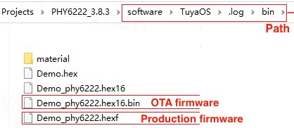
Flashing method
Open the flashing tool from pc\tools\PHY6222.
-
Connect the device to the computer through a USB to TTL converter.
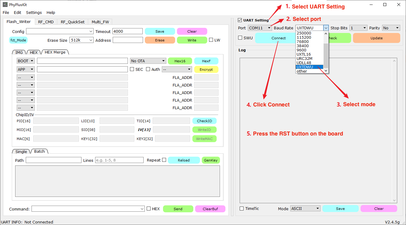
-
Serial port is connected.
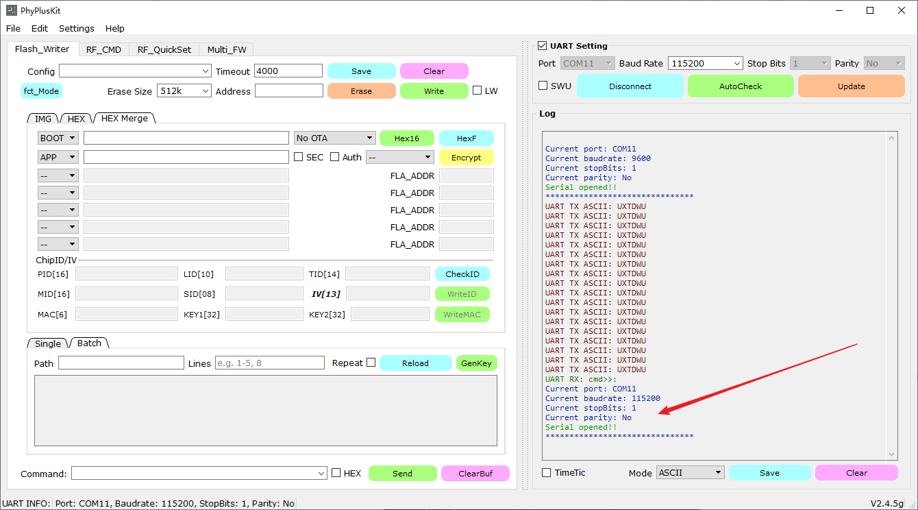
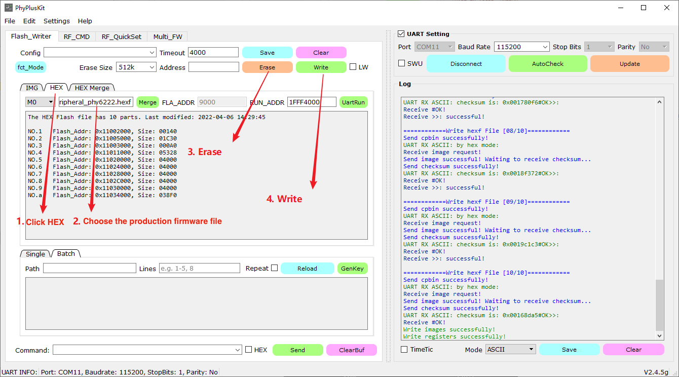
-
Import the firmware binary file and proceed with erasing and writing.
Features
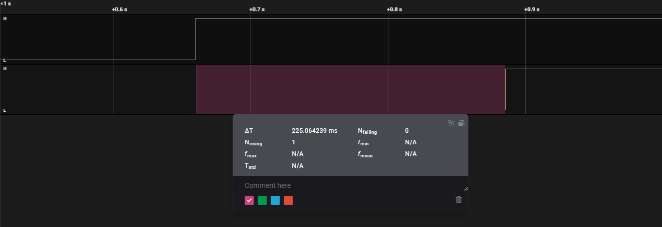
Startup time
-
Use a logic analyzer to measure the signal time difference between the VCC pin and the startup time detection pin.
-
Detection pins: peripheral → startup time detection pin
Flash partition
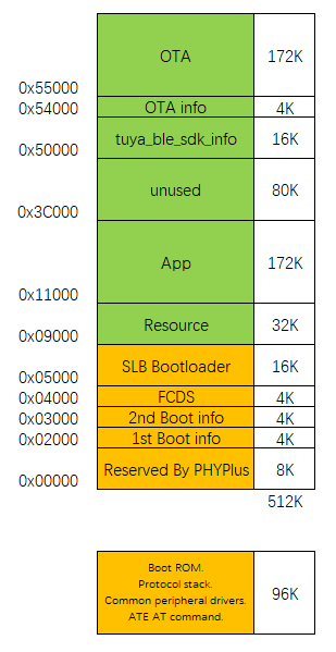
Adjust flash partitions
In the original project, you can modify the following macros to adjust the default flash partitions.
// Flash
#ifndef BOARD_FLASH_BULK_DATA_START_ADDR
#define BOARD_FLASH_BULK_DATA_START_ADDR        (0x4C000)
#endif

#ifndef BOARD_FLASH_TUYA_INFO_START_ADDR
#define BOARD_FLASH_TUYA_INFO_START_ADDR        (0x50000)
#endif

#ifndef BOARD_FLASH_OTA_INFO_ADDR
#define BOARD_FLASH_OTA_INFO_ADDR               (0x54000)
#endif

#ifndef BOARD_FLASH_OTA_START_ADDR
#define BOARD_FLASH_OTA_START_ADDR              (0x55000)
#endif

#ifndef BOARD_FLASH_OTA_END_ADDR
#define BOARD_FLASH_OTA_END_ADDR                (0x80000)
#endif

#ifndef BOARD_FLASH_OTA_SIZE
#define BOARD_FLASH_OTA_SIZE                    (BOARD_FLASH_OTA_END_ADDR - BOARD_FLASH_OTA_START_ADDR)
#endif
To change the OTA memory location, besides editing the above macro, you also need to edit the bootloader project accordingly.
-
Open the bootloader project from
\vendor\phy6222_ble\sdk\phy62xx-sdk-v3\example\OTA\slboot. -
Edit
SLB_EXCH_AREA_BASEandSLB_EXCH_AREA_SIZEand then compile the bootloader project.
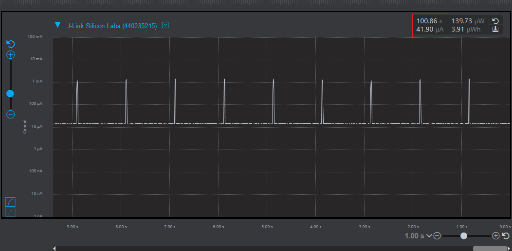
Power consumption
Measure the average power consumption of typical one-second advertising.
Power consumption in sleep mode is 13 μA.
RTC precision
-
Normal operation mode: The time drift is less than two seconds within 20 hours.
-
Sleep mode: The time drift is about eight seconds within in 11 hours.
Is this page helpful?
YesFeedbackIs this page helpful?
YesFeedback


