Bluetooth LE–FR801x
This topic describes the basics of the chip platform used in TuyaOS development. For more information, visit Tuya Developer Forum.
Hardware environment
Datasheet
The datasheet can be found in hardware\FR8018HA\chip_manual\.
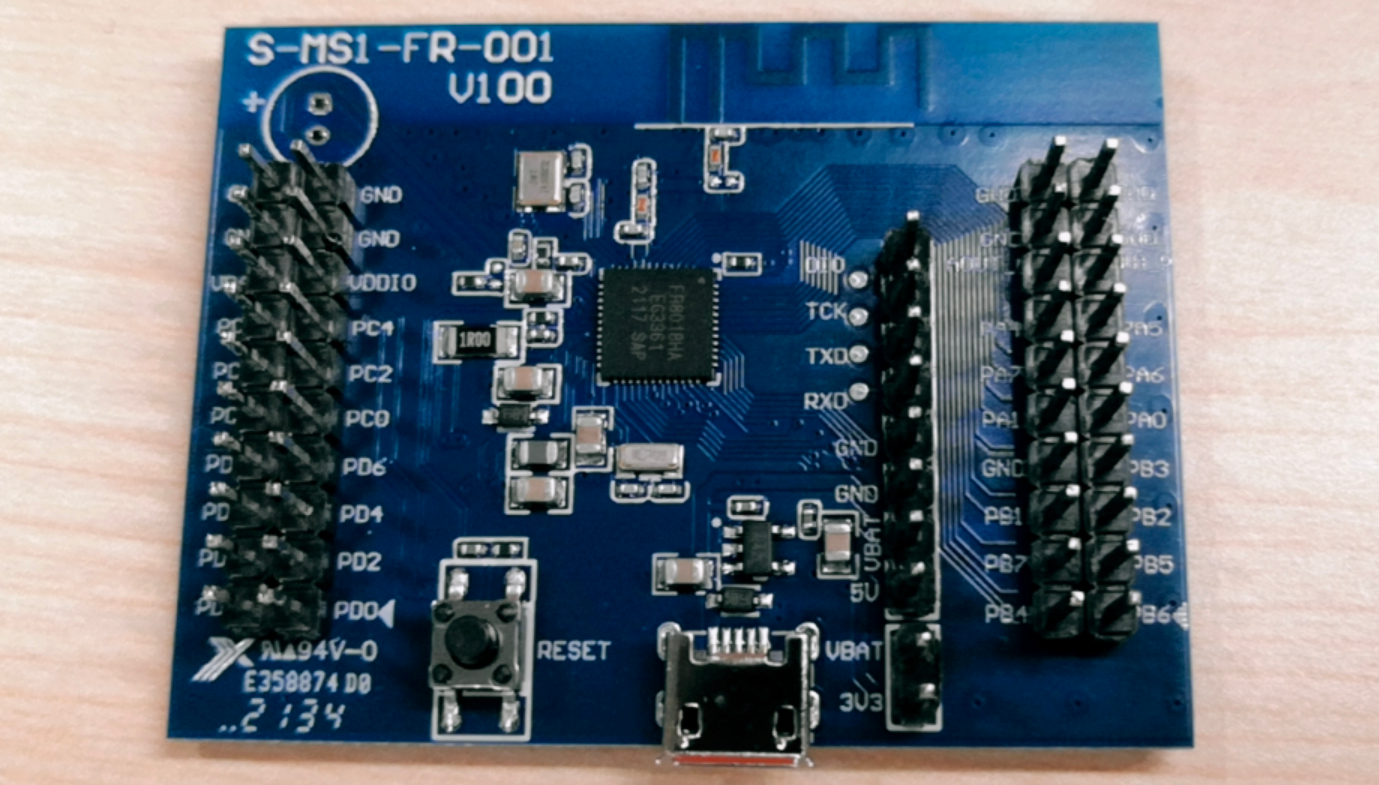
Development board
You can purchase the FR8018HA Bluetooth development board (part number: 2.05.03.00198) from the Tuya Developer Platform.
Peripherals
PMU
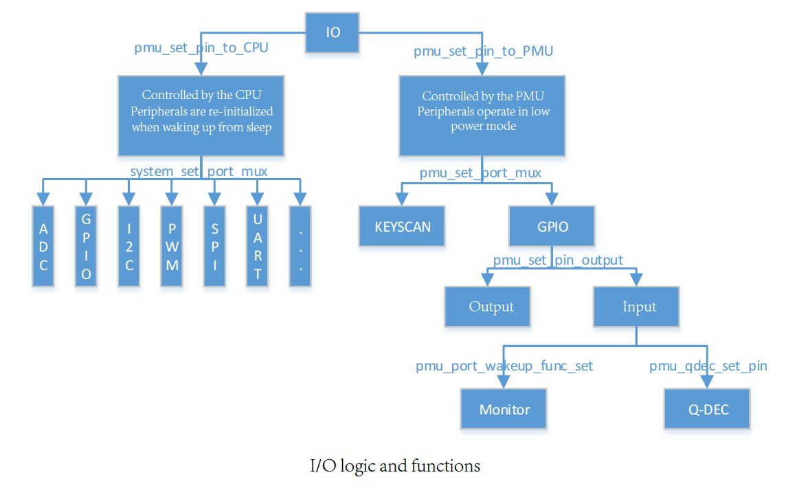
The FR801xH series has four sets of I/O pins, with eight pins per set. The number of I/O pins brought out varies by chip model. Each I/O pin can be set to pull-up mode. The pull-up resistor is about 50 kΩ. The operating state and mode of an I/O pin can be controlled by either the CPU or power management unit (PMU).
- PMU: operates in low power mode.
- CPU: powers off in low power mode.
Unlike PMU, peripherals controlled by the CPU are re-initialized when waking up from sleep.
The following diagram shows the control logic and function configuration.
GPIO
The FR8018H has 32 GPIOs, but not all of them are brought out. PC4 is completely unavailable.
When testing GPIO input and output, the logic pin numbers used in the host software range from 0 to 31. Here are their corresponding physical pin names:
| FR8018H | Logic | FR8018H | Logic | FR8018H | Logic | FR8018H | Logic |
|---|---|---|---|---|---|---|---|
| PA0 | 0 | PB0 | 8 | PC0 | 16 | PD0 | 24 |
| PA1 | 1 | PB1 | 9 | PC1 | 17 | PD1 | 25 |
| PA2 | 2 | PB2 | 10 | PC2 | 18 | PD2 | 26 |
| PA3 | 3 | PB3 | 11 | PC3 | 19 | PD3 | 27 |
| PA4 | 4 | PB4 | 12 | PC4 | 20 | PD4 | 28 |
| PA5 | 5 | PB5 | 13 | PC5 | 21 | PD5 | 29 |
| PA6 | 6 | PB6 | 14 | PC6 | 22 | PD6 | 30 |
| PA7 | 7 | PB7 | 15 | PC7 | 23 | PD7 | 31 |
UART
This platform has two UARTs (UART0 and UART1). You can map the UART to any of the I/O pins. The serial port testing feature in the host software can only test two specified I/Os.
| UART | Feature | Pin | Description |
|---|---|---|---|
| UART0 | TX | PA1 | Log |
| UART0 | RX | PA0 | |
| UART1 | TX | PA3 | Flashing, authorization, and testing. |
| UART1 | RX | PA2 |
SPI (SSP)
In the FR8018 datasheet and .c files, SPI is described as SSP. FR8018H has only one SSP peripheral, which is the SSP0. You can connect SSPDIN and SSPDOUT to perform a test.
| SSP | Pin | Pin |
|---|---|---|
| SSP0 | CS | PA5 |
| SSP0 | SSPCLK | PA4 |
| SSP0 | SSPDIN | PA7 |
| SSP0 | SSPDOUT | PA6 |
Rate:
- 125000
- 250000
- 500000
- 1000000
- 2000000
I2C
FR8018H has two I2Cs, which can be mapped to any of the I/O pins (except for PC4). To display SDK information (TuyaOS demo), the OLED is pre-initialized. Therefore, only one I2C can be used for testing.
| Feature | Pin |
|---|---|
| I2C0_SCL | PD0 |
| I2C0_SDA | PD1 |
PWM
| Channel | Pin |
|---|---|
| 0 | PC0 |
| 1 | PC1 |
| 2 | PC2 |
| 3 | PC3 |
| 4 | PB4 |
| 5 | PB5 |
ADC
Only support 10-bit resolution.
| Channel | Pin |
|---|---|
| 0 | PD4 |
| 1 | PD5 |
| 2 | PD6 |
| 3 | PD7 |
Key control
PB6 (14)
Press the button to wake up the device.
Press and hold the button for three seconds to factory reset the device.
Power-on detection pin
PC5 (21)
Set this pin to high after entering the main function.
Software environment
Keil
-
Download Keil from the Arm Keil website. mdk528a.exe is recommended. During installation, keep all the default settings.
-
If you are prompted to install a driver, continue with Install.
-
When opening Keil, if you are prompted to install a software pack, close the window.
-
After Keil is installed, add the path of the
UV4.exefile to the environment variable. For example:TUYAOS_COMPILE_TOOL:C:\Keil_v5\UV4, as shown below.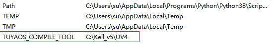
Develop software
Flash and RAM footprint
-
Disable the testing feature.
#define TUYA_SDK_TEST 0 -
Disable Tuya logging.
#define ENABLE_LOG 0 #define BOARD_ENABLE_LOG 0 -
After a full compilation of the whole project, open the
.mapfile. The flash and RAM footprint: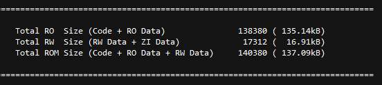
OTA
Before an OTA firmware update, modify the version number firmware_version in proj_main.c. The bootloader checks the version number at each update. The new version must be higher than the previous one.

os_timer
os_timer cannot be used in an interrupt. This is because ke_timer_set in os_timer manipulates the linked list. The underlying Bluetooth stack uses ke_timer_set. When the underlying stack uses ke_timer_set, if os_timer is called by an interrupt, ke_timer_set will manipulate the same linked list in the interrupt. This can disrupt the linked list and result in problems.
Firmware flashing
Wire connection
To flash firmware to the device, connect the device and the USB to TTL converter as described below.
| USB to TTL converter | Device |
|---|---|
| VCC | VCC |
| GND | GND |
| TX | RX (PA2) |
| RX | TX (PA3) |
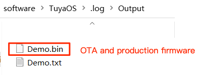
Firmware description
The production firmware and the OTA update use the same file, as shown below.
Flashing method
-
Open the flashing tool from
pc\tools\FR8018HA\tools\FR8010H_Download_Tool.exe. -
Connect the device to the computer through a USB to TTL converter.
-
Import the firmware binary file and proceed with erasing and writing.
Features
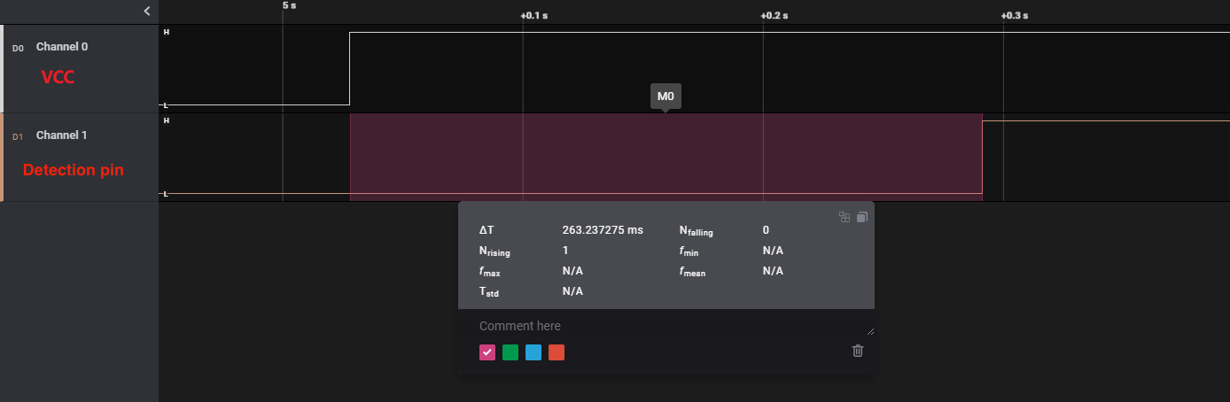
Startup time
-
Use a logic analyzer to measure the signal time difference between the
VCC pinand the startup time detection pin. -
Detection pins: peripheral → startup time detection pin
Flash partition
Flash partitions and sizes
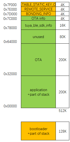
-
In the original project, you can modify the following macros to adjust the default flash partitions.
// Flash #ifndef BOARD_FLASH_BULK_DATA_START_ADDR #define BOARD_FLASH_BULK_DATA_START_ADDR (0x74000) #endif #ifndef BOARD_FLASH_TUYA_INFO_START_ADDR #define BOARD_FLASH_TUYA_INFO_START_ADDR (0x78000) #endif #ifndef BOARD_FLASH_OTA_INFO_ADDR #define BOARD_FLASH_OTA_INFO_ADDR (0x7C000) #endif #ifndef BOARD_FLASH_OTA_START_ADDR #define BOARD_FLASH_OTA_START_ADDR (0x32000) #endif #ifndef BOARD_FLASH_OTA_END_ADDR #define BOARD_FLASH_OTA_END_ADDR (0x64000) #endif #ifndef BOARD_FLASH_OTA_SIZE #define BOARD_FLASH_OTA_SIZE (BOARD_FLASH_OTA_END_ADDR - BOARD_FLASH_OTA_START_ADDR) #endif -
To change the OTA memory location, besides editing the above macro, you also need to change the start address in
proj_main.caccordingly.
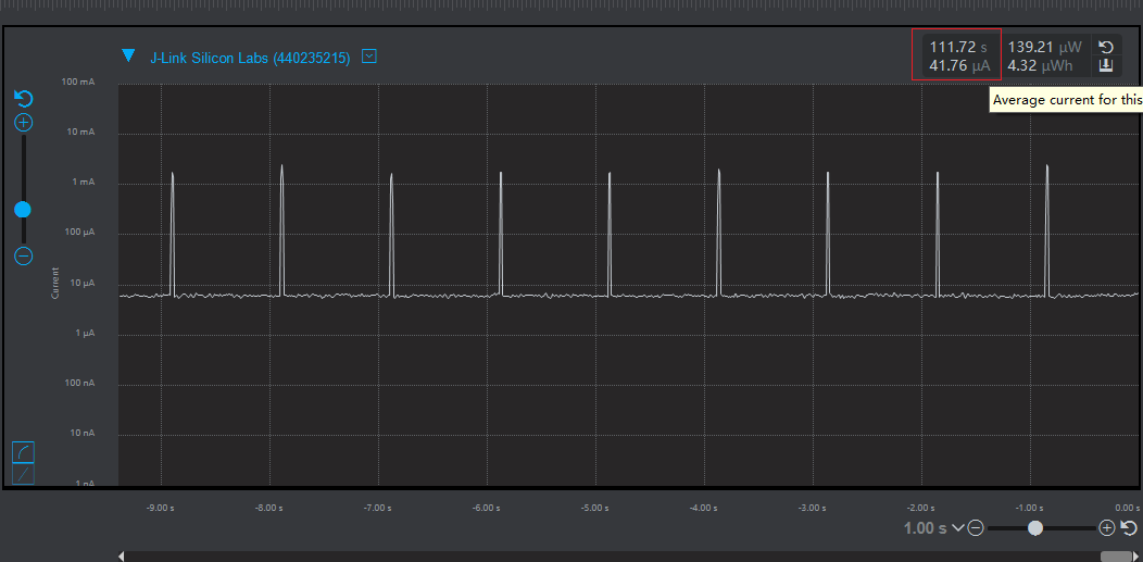
Power consumption
Measure the average power consumption of typical one-second advertising for over 100 seconds.
Local clock testing
The local clock has a time drift of less than one second within 12 hours.
Is this page helpful?
YesFeedbackIs this page helpful?
YesFeedback


