CBU Module
This topic describes information about the hardware design of CBU modules.
Scope
The low-power Wi-Fi CBU module developed by Tuya is composed of a highly integrated radio-frequency identification (RFID) chip BK7231N and a few peripheral components. It supports a dual connection of AP and station as well as a Bluetooth connection.
Features
- Built-in low-power 32-bit CPU, 256 kbit RAM, and 2 MB flash.
- The maximum clock speed is 120 MHz.
- Full functionality of IEEE 802.11b/g/n Wi-Fi connectivity.
- Integral Wi-Fi and Bluetooth coexistence interface.
- The maximum output power is +16 dBm for 802.11b transmission.
- The transmit power in Bluetooth mode is 6 dBm.
- Two pairing modes are supported, namely Wi-Fi Easy Connect (EZ mode) and access point (AP) mode. Both Android and iOS devices are available.
- Two types of antenna are supported, namely the PCB antenna and FPC antenna.
- The PCB antenna peak gain is 2.2 dBi.
- Operating voltage: 3.0V to 3.6V
- Operating temperature: -40°C to 105°C
For more information, see CBU Module Datasheet.
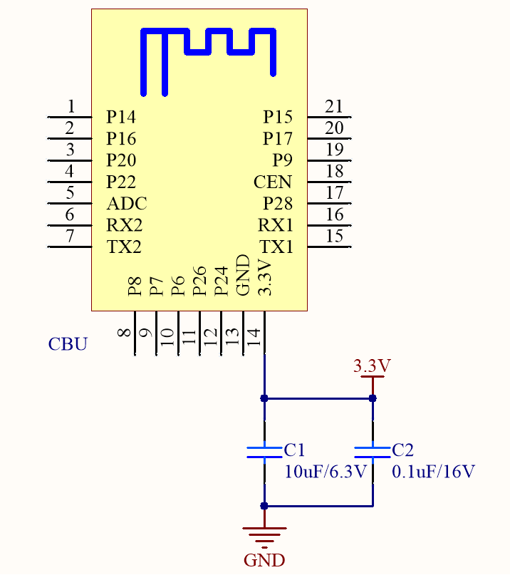
Minimal system diagram
Things to note
Power supply circuits
| Operating modes | Status (Ta = 25°C) | Average | Max (Typical) | Unit |
|---|---|---|---|---|
| Bluetooth mode | The module is in EZ mode. The network status indicator blinks quickly. | 70 | 270 | mA |
| AP mode | The module is in AP mode. The network status indicator blinks slowly. | 80 | 305 | mA |
| EZ mode | The module is in EZ mode. The network status indicator blinks quickly. | 87 | 380 | mA |
| Network connected | The module is connected to the cloud. The network status indicator is steady on. | 73 | 355 | mA |
| Unstable network connection | The connection between the module and the hotspot is intermittent. The network status indicator is steady on. | 205 | 350 | mA |
| Network disconnected | The module is disconnected from the cloud. The network status indicator is steady off. | 70 | 270 | mA |
| Module disabled | The module’s clock enable (CEN) pin is pulled down. | 330 | - | μA |
RF power
| Modes | Mode | Rate | Transmit/Receive power | Peak (Typical) | Unit |
|---|---|---|---|---|---|
| Transmit | 802.11b | 11 Mbit/s | +16 dBm | 300 | mA |
| Transmit | 802.11g | 54 Mbit/s | +15 dBm | 280 | mA |
| Transmit | 802.11n | MCS 7 | +14 dBm | 273 | mA |
| Receive | 802.11b | 11 Mbit/s | Continuous reception | 82 | mA |
| Receive | 802.11g | 54 Mbit/s | Continuous reception | 82 | mA |
| Receive | 802.11n | MCS 7 | Continuous reception | 82 | mA |
- The maximum power consumption in operation mode is 3.3V/205 mA on average. The transmission peak current can be up to 300 mA. Since the capacitance of the electrolytic capacitor on the power terminal is large, a large current will flow through it in cold start mode. It is recommended to select a power supply with steady-state power of ≥ 3.3V/300 mA and peak current limit of ≥ 400 mA.
Consider the power consumption of other components when you design the power supply circuit. - Place the filter capacitors C1 and C2 near the power pin of the module.
- Pin description
- ADC pin: 10-bit ADC that can convert voltage from 0 to 2.4V.
- RX1 and TX1, interface with external UART1, are user ports by default and can be used to download code. You can also configure them as GPIO pins.
- RX2 and TX2, interface with external UART2, are log printing ports by default. You can also configure them as GPIO pins but it is not recommended to do so if you have enough GPIO pins.
- P6, P7, P8, P24, and P26 can be used for 5-channel PWM or configured as GPIO pins.
- The module’s clock enable (CEN) pin has internal pull-up resistors. If the pin is not used, it can float.
Antenna clearance description
Things to note
-
Do not use metal shells or plastic shells with metallic paint or coating in the direction of the antenna radiation. Do not use metal objects such as screws and rivets near the antenna, which might affect the antenna efficiency.
-
Try to increase the distance from the top shell to the antenna to minimize the impact on antenna performance.
-
Try to increase the distance from the upper and bottom shells to the antenna to minimize the impact on antenna performance.
-
Keep the module away from speakers, power switches, cameras, HDMI, USB, and other high-speed signals to avoid interference.
-
Avoid metal shielding near the antenna. If co-channel interference occurs, you must evaluate the impact on the antenna performance and ensure the isolation from interference.
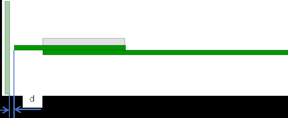
Placement
-
Horizontal placement
We recommend that you place the module at the edge of the backplane with the antenna facing outward, and flush the module’s GND terminal with the backplane’s GND terminal. Both terminals are fully connected.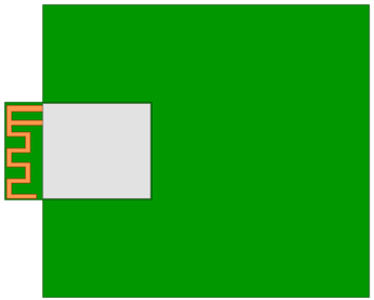
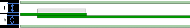
-
Embedded placement
Embed the module into the backplane through a slot that is flushed with or deeper than the module’s GND terminal. The side of the slot must be 15 mm or farther from the module’s board edge.
A wider slot can achieve better performance that is still weaker than that of horizontal placement.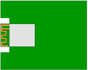
-
Vertical placement
Insert the module vertically into the backplane slot with the antenna facing upward. The module’s GND terminal and the backplane’s GND terminal must be fully connected. We recommend that you keep a clearance distance of 15 mm or more around the antenna.
RF test items and metrics
The antenna is susceptible to the distance from the shell to the surrounding components. We recommend that you test the radio frequency (RF) performance after the final test. The RF test items and metrics are listed in the following table.
| No. | Test item | Test metric |
|---|---|---|
| 1 | Increasing indoor distance | ≥ 25 m |
| 2 | Increasing outdoor distance | ≥ 75m |
| 3 | Total radiated power (TRP) in the signaling mode of end devices (test mode of 11B 1 Mbit/s). | ≥ 10 dBm |
| 4 | Total isotropic sensitivity (TIS) of end devices | ≤ -62 dBm |
- Items 3 and 4 must be tested in a dark chamber of the antenna manufacturers or certified organizations.
- The test items apply to most Wi-Fi products, excluding certain special products.
Is this page helpful?
YesFeedbackIs this page helpful?
YesFeedback


