SPI Interface
This topic describes information about designing the SPI interface.
SPI bus
SPI is a full-duplex, synchronous communication bus and supports chip select. The data transmission speed is overall faster than the I2C bus and can reach Mbit/s data rates. SPI does not specify the response mechanism. Typically, data is sampled on the rising edge of the clock and driven on the falling edge of the clock.
SPI uses a controller-peripheral architecture usually with a single controller. Multiple peripherals can be supported through selection with individual chip select. The controller generates the clock pulses and sends data with the most-significant bit (MSB) first.
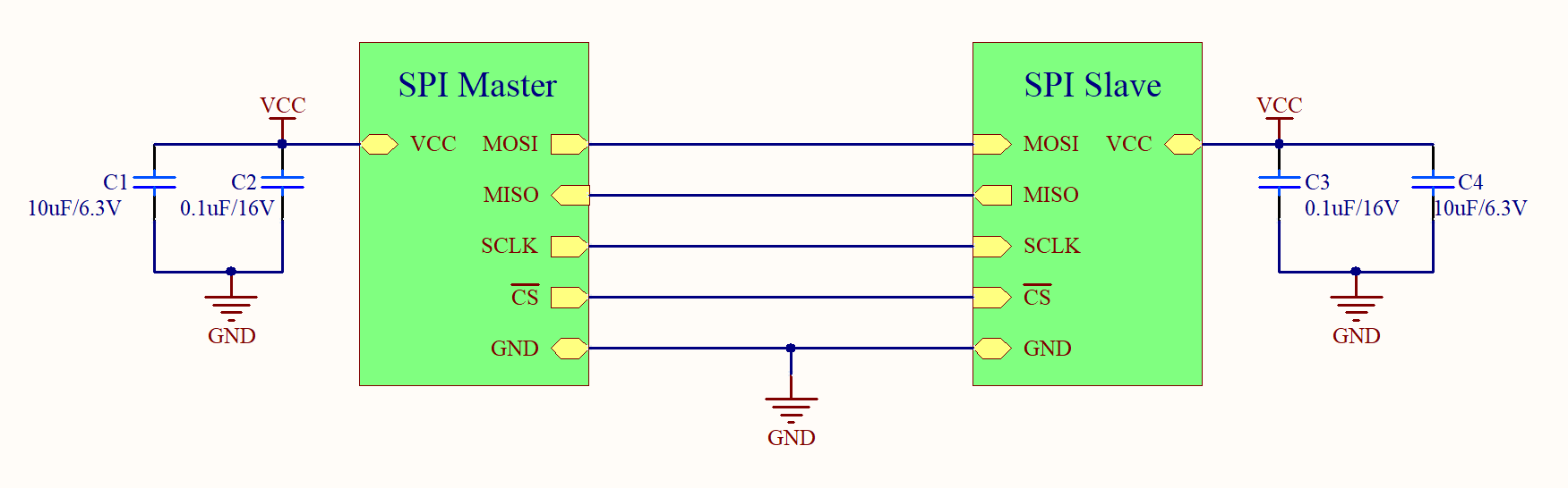
SPI interface
The SPI bus specifies four logic signals:
- MISO: Data is sent from the peripheral to the controller.
- MOSI: Data is sent from the controller to the peripheral.
- SCLK: Serial clock, generated by the controller.
- SS: Chip select, used to enable the peripheral.
Take care of the following:
-
Clock polarity (CPOL) sets the level of the clock signal during the idle state. Clock phase (CPHA) sets the clock edge for reading and sending data.
SPI mode CPOL CPHA CPOL in idle state CPHA used to sample and shift data 0 0 0 Logic low Data sampled on the rising edge and shifted out on the falling edge. 1 0 1 Logic low Data sampled on the falling edge and shifted out on the rising edge. 2 1 1 Logic high Data sampled on the falling edge and shifted out on the rising edge. 3 1 0 Logic high Data sampled on the rising edge and shifted out on the falling edge. -
A small value 10Ω to 50Ω resistor can be placed in series on the four signal wires to increase the impedance and get an impedance matching for suppression of undesired signal reflection.
-
If you only connect to one peripheral and have insufficient I/O pins, you can pull down the chip select (CS) pin. This way, you can have an extra I/O pin available. The pull-down resistor can be about 10 kΩ.
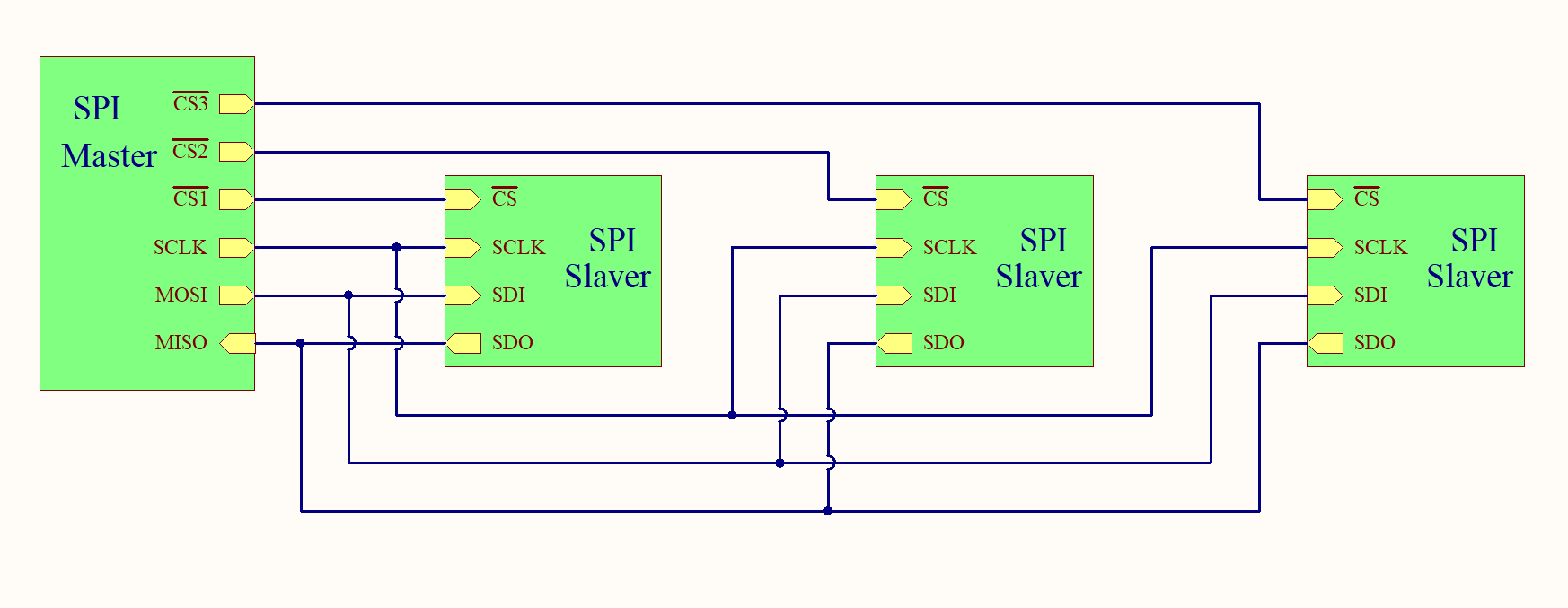
Multi-peripheral configuration
Typical multi-peripheral mode
In regular mode, an individual chip select signal for each peripheral is required from the controller. Once the chip select signal is enabled (pull-down) by the controller, the clock and data on the MOSI/MISO lines are available for the selected peripheral. If multiple chip select signals are enabled, the data on the MISO line is corrupted, because there is no way for the controller to identify which peripheral is transmitting the data.
As the number of peripherals increases, the number of chip select lines from the controller increases. This can quickly add to the number of inputs and outputs needed from the controller and limit the number of peripherals that can be used. There are different techniques that can be used to increase the number of peripherals in regular mode. For example, using a multiplexer to generate a chip select signal.
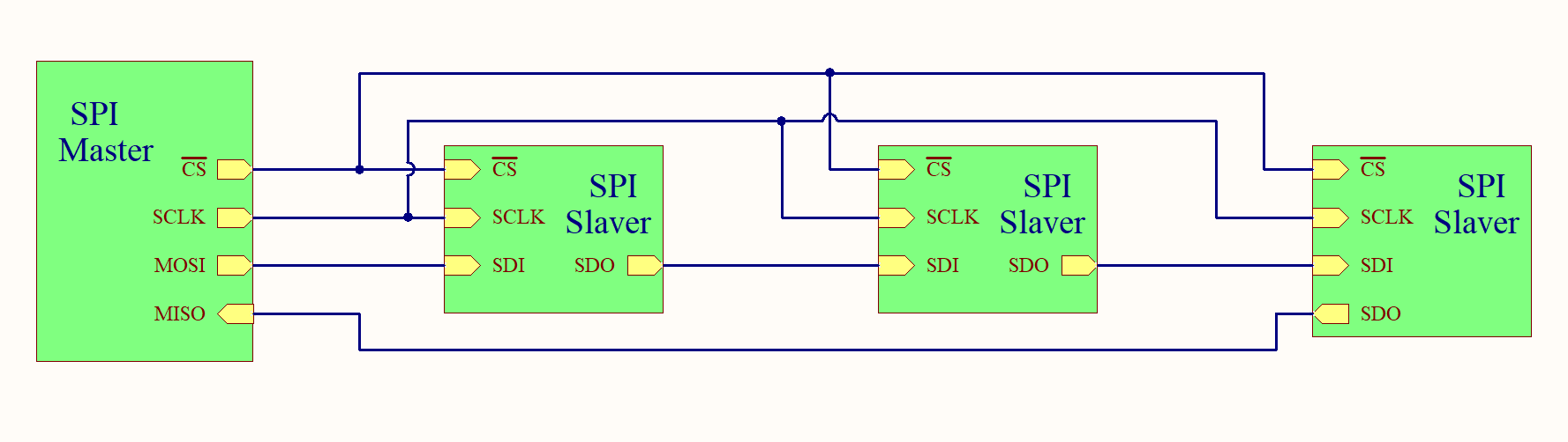
Daisy-chain mode
In daisy-chain mode, the peripherals are configured so that the chip select signal for all peripherals is tied together and data propagates from one peripheral to the next. In this configuration, all peripherals receive the same SPI clock at the same time. The data from the controller is directly sent to the first peripheral and that peripheral provides data to the next peripheral and so on.
In this method, data is propagated from one peripheral to the next so the number of clock cycles required to transmit data is proportional to the peripheral position in the daisy chain. For example, in an 8-bit system, 24 clock pulses are required for the data to be available on the third peripheral, compared to only eight clock pulses in regular SPI mode.
Daisy-chain mode is not necessarily supported by all SPI devices. Make sure to see the product datasheet to confirm if the daisy chain is available.
Is this page helpful?
YesFeedbackIs this page helpful?
YesFeedback


