CBx Series Modules
This topic describes information about implementing serial peripheral interface (SPI) communication between CBx series modules and MCUs.
Overview
CBx series is a Wi-Fi and Bluetooth Low Energy (Bluetooth LE) combo module developed by Tuya Smart. It is composed of a highly integrated radio-frequency identification (RFID) chip BK7231N and a few peripheral components. It can run in Wi-Fi station mode and access point (AP) mode as well as support connection over Bluetooth Low Energy.
Applicability
| Module/chip model | MISO pin No. | MISO silk screen | MOSI pin No. | MOSI silk screen | SCLK pin No. | SCLK silk screen | CS pin No. | CS silk screen |
|---|---|---|---|---|---|---|---|---|
| BK7231N | 14 | P17 | 12 | P16 | 11 | P14 | 13 | P15 |
| CBU | 20 | P17 | 2 | P16 | 1 | P14 | 21 | P15 |
| CBU-IPEX | 20 | P17 | 2 | P16 | 1 | P14 | 21 | P15 |
| CB3SE | 13 | P17 | 14 | P16 | 4 | P14 | 9 | P15 |
SPI interface
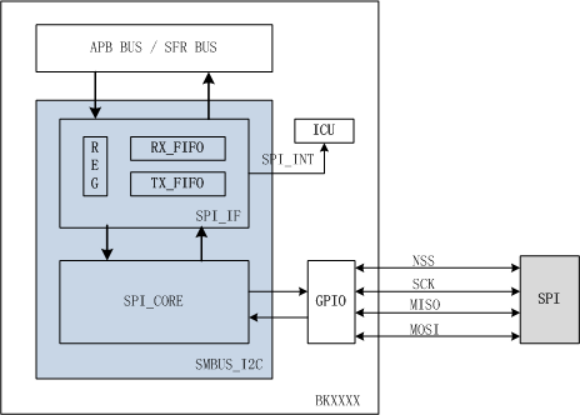
The SPI allows full-duplex synchronous serial communication. The SPI bus complies with the de-facto standard and supports four working modes. It uses three (single-to-single) or four-wire (multiple-to-multiple) for communication as needed. The built-in receive and transmit FIFO can help you reduce software overhead.
-
The following diagram shows the internal structure and connection to peripherals.
-
Features
- Controller-peripheral architecture.
- Full-duplex synchronous serial communication interface.
- A low-speed SPI controller/peripheral interface, with a maximum clock rate of 8 MHz.
- The interface can send data with the most-significant bit (MSB) first, or the least-significant bit (LSB) first.
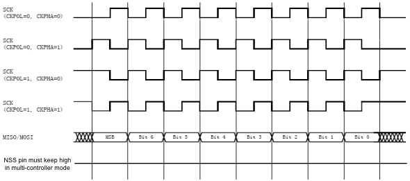
- SPI has four working modes, which are obtained by the combination of serial clock polarity (CPOL) and phase (CPHA).
- If the initial state of the serial clock (SCLK) is low, data is sampled on the rising edge and shifted out on the falling edge. (CPOL = 0, CPHA = 0)
- If the initial state of the SCLK is low, data is sampled on the falling edge and shifted out on the rising edge. (CPOL = 0, CPHA = 1)
- If the initial state of the SCLK is high, data is sampled on the rising edge and shifted out on the falling edge. (CPOL = 1, CPHA = 0)
- If the initial state of the SCLK is high, data is sampled on the falling edge and shifted out on the rising edge. (CPOL = 1, CPHA = 1)
- The 64-byte receive and transmit FIFO.
SPI working modes
-
When the SPI device acts as the controller, it generates the SCLK. The clock rate is set with the software. The following diagram shows the four working modes.
-
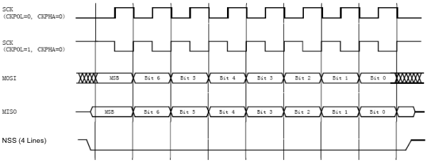
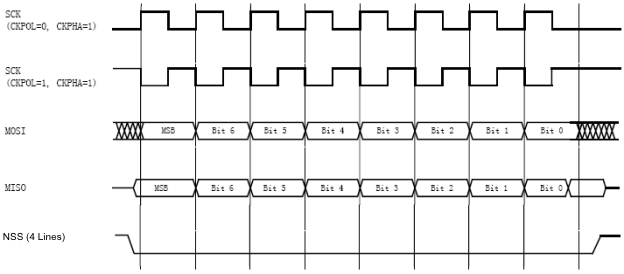
When the SPI device acts as the peripheral, the SCLK is an input signal. To sample data correctly, the clock polarity and phase must match the controller. Data on the MOSI pin is sampled in the middle of the data bit.
- Peripheral timing diagram (CPHA = 0)
- Peripheral timing diagram (CPHA = 1)
Is this page helpful?
YesFeedbackIs this page helpful?
YesFeedback


