MCU Integration Protocol
Serial communication convention
- Baud: 115200
- Data bit: 8
- Parity check: none
- Stop bit: 1
- Data flow control: none
- MCU: microcontroller unit. Your MCU communicates with Tuya’s modules through the serial protocol. This protocol is designed to enable full-duplex communication between the device and the server.
Frame format description
| Field | Length (byte) | Description |
|---|---|---|
| Header | 2 | It is fixed to 0x55aa. |
| Version | 1 | It is used for updates and extensions. |
| Command | 1 | Frame type |
| Data length | 2 | Big-endian |
| Data | N | |
| Checksum | 1 | Start from the header, add up all the bytes, and then divide the sum by 256 to get the remainder. |
Note:
- All data greater than one byte is transmitted in big-endian format.
- All sample data in the protocol is in hexadecimal format.
- The NB-IoT module sends packets and waits for response packets. If no response is received within one second, the unanswered packets will be retransmitted three times.
- Generally, one command is sent by one party and received by the other party synchronously. That is, one party sends a command and waits for a response from the other party. If the sender does not receive a correct response packet within a specified time period, the transmission times out.
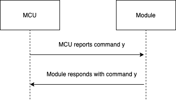
For specific communication modes, see the protocol list in this topic.
The MCU reports status synchronously. Assume that the MCU reports a command y. The data transmission is as follows. The MCU reports statistical data:
Protocol list
Query product information
- Product ID (PID): It is automatically generated for each product created on the Tuya Developer Platform to record product information in the cloud.
- Product information consists of the product ID and MCU software version number.
- MCU software version format: It is expressed in dot-decimal notation,
x.x.x(0 ≤ x ≤ 99), andxis a decimal digit.
The module sends the following command:
| Field | Length (byte) | Description |
|---|---|---|
| Header | 2 | 0x55aa |
| Version | 1 | 0x00 |
| Command | 1 | 0x01 |
| Data length | 2 | 0x0000 |
| Data | 0 | None |
| Checksum | 1 | Start from the header, add up all the bytes, and then divide the sum by 256 to get the remainder. |
The module sends the following command:
55 aa 00 01 00 00 00
The MCU returns the following command:
| Field | Length (byte) | Description |
|---|---|---|
| Header | 2 | 0x55aa |
| Version | 1 | 0x00 |
| Command | 1 | 0x01 |
| Data length | 2 | N |
| Data | N | {"p":”vHXEcqntLpkAlOsy”,"v":”1.0.0”} |
| Checksum | 1 | Start from the header, add up all the bytes, and then divide the sum by 256 to get the remainder. |
For example, {"p":”vHXEcqntLpkAlOsy”,"v":”1.0.0”}
p indicates the product ID is vHXEcqntLpkAlOsy, mapping the PID of a product created on the Tuya Developer Platform.
v indicates the MCU version is 1.0.0.
The MCU returns the following command:
55 aa 00 01 00 24 7b 22 70 22 3a 22 76 48 58 45 63 71 6e 74 4c 70 6b 41 6c 4f 73 79 22 2c 22 76 22 3a 22 31 2e 30 2e 30 22 7d bf
Report network status
| Network status | Description | Status value |
|---|---|---|
| Status 1 | Searching for NB-IoT networks. | 0x01 |
| Status 2 | The NB-IoT network is found. | 0x02 |
| Status 3 | The telecom platform is connected, and the device is not bound. | 0x03 |
| Status 4 | The device is bound and connected to the Tuya Cloud. | 0x04 |
The module sends the following command:
| Field | Length (byte) | Description |
|---|---|---|
| Header | 2 | 0x55aa |
| Version | 1 | 0x00 |
| Command | 1 | 0x02 |
| Data length | 2 | 0x0001 |
| Data | 1 | Indicates the working status of the NB-IoT module: 0x01: status 1 0x02: status 2 0x03: status 3 0x04: status 4 |
| Checksum | 1 | Start from the header, add up all the bytes, and then divide the sum by 256 to get the remainder. |
The module sends the following command:
55 aa 00 02 00 01 04 06 (The device is bound and connected to the cloud.)
The MCU returns the following command:
| Field | Length (byte) | Description |
|---|---|---|
| Header | 2 | 0x55aa |
| Version | 1 | 0x00 |
| Command | 1 | 0x02 |
| Data length | 2 | 0x0000 |
| Data | 0 | None |
| Checksum | 1 | Start from the header, add up all the bytes, and then divide the sum by 256 to get the remainder. |
The MCU returns the following command:
55 aa 00 02 00 00 01
Reset the NB-IoT module and restore to factory defaults
The device is reset. The module sends an activation request to the cloud and is restored to factory default settings.
The MCU sends the following command:
| Field | Length (byte) | Description |
|---|---|---|
| Header | 2 | 0x55aa |
| Version | 1 | 0x00 |
| Command | 1 | 0x03 |
| Data length | 2 | 0x0000 |
| Data | 0 | None |
| Checksum | 1 | Start from the header, add up all the bytes, and then divide the sum by 256 to get the remainder. |
The MCU sends the following command:
55 aa 00 03 00 00 02
The module returns the following command:
| Field | Length (byte) | Description |
|---|---|---|
| Header | 2 | 0x55aa |
| Version | 1 | 0x00 |
| Command | 1 | 0x03 |
| Data length | 2 | 0x0000 |
| Data | 0 | None |
| Checksum | 1 | Start from the header, add up all the bytes, and then divide the sum by 256 to get the remainder. |
The module returns the following command:
55 aa 00 03 00 00 02
Report real-time status
Scenario: This command allows devices that require real-time pushes, such as alarms, to make quick status reporting.
Note: This protocol allows the MCU to report real-time status data.
- Status data is directly reported to the cloud, so the device must be connected to the cloud already. Otherwise, data reporting failed.
- Using this synchronous command, the MCU reports data and waits five seconds for a response from the module. If the signal is good, the module can receive the response from the cloud within five seconds.
- You can set packets to be transmitted in single or multiple data units. For more information about packets, see the examples in this section.
The MCU sends the following command:
| Field | Length (byte) | Description |
|---|---|---|
| Header | 2 | 0x55aa |
| Version | 1 | 0x00 |
| Command | 1 | 0x05 |
| Data length | 2 | It depends on types and the number of data units of status. |
| Data | N | Single or multiple data units of status. |
| Checksum | 1 | Start from the header, add up all the bytes, and then divide the sum by 256 to get the remainder. |
The module returns the following command:
| Field | Length (byte) | Description |
|---|---|---|
| Header | 2 | 0x55aa |
| Version | 1 | 0x00 |
| Command | 1 | 0x05 |
| Data length | 2 | 0x0001 |
| Data | 1 | 0x00: success. 0x01: failure. |
| Checksum | 1 | Start from the header, add up all the bytes, and then divide the sum by 256 to get the remainder. |
Report a single data unit of status:
The DP 109 is a Boolean variable, and the value is 1.
55 aa 00 05 00 05 6d 01 00 01 01 79
Report multiple data units of status
The DP 109 is a Boolean variable, and the value is 1.
The DP 102 is a string variable, and the value is 201804121507. The value is transferred in ASCII mode.
55 aa 00 05 00 15 6d 01 00 01 01 66 03 00 0c 32 30 31 38 30 34 31 32 31 35 30 37 5d
Report status of record type
Scenario: For the door lock, its status data of multiple data points (DPs) need to be processed as one piece of record in the server. In case of transient network failure, this command can store data that failed to be reported. The time used in the reported data is the local time.
This command allows the MCU to send a piece of record-type data that includes multiple DPs to the NB-IoT module for reporting it to the cloud. If the device is disconnected from the network when the data is being reported, the module will store this data and send it on the next reporting operation.
- Each time when a stranded record is reported successfully, the module returns the value
0x01through the command0x08. - If the network works fine, when the module is powered on, it takes about 30 seconds to connect to the cloud. Once status data is generated, the MCU will receive network status from the module. If the MCU does not receive the network status packet for more than six seconds, it still sends data to the module and waits for the data reporting result.
- The maximum length of the data area for reporting one record (multiple data units of status) is 100 bytes. The actual length varies depending on the DP data. If no network is available, in case of exceeding the specified length, the NB-IoT module returns a message indicating failed reporting.
- The module can store a maximum of 20 historical records. When the limit is reached, the newest record will overwrite the oldest one.
- When the module successfully reports a record or stores a stranded record due to network failure, it returns
0x00indicating successful reporting. When the network works fine, each time the module successfully reports one of the stranded records, it returns0x01. In other cases, it returns0x02to indicate reporting failed. - The use of time data is to ensure that the record data reflects the actual events when the device is disconnected. If you use the time when the record data arrives at the server, the time of a stranded record will be inconsistent with the time when the event actually occurs. Therefore, when a device is paired for the first time, if the network works fine, the required time data can be obtained through the protocol. Each time when a record with time data of the device is reported, the time that is given by the device prevails.
The MCU sends the following command:
| Field | Length (byte) |
Description |
|---|---|---|
| Header | 2 | 0x55aa |
| Version | 1 | 0x00 |
| Command | 1 | 0x08 |
| Data length | 2 | It depends on types and the number of data units of status. |
| Data | 7 | The data length is seven bytes. This field is reserved to be compatible with the original protocol. For the NB-IoT module, you only need to set this field to 0. The module will automatically populate the internal RTC time to the record type data. |
| N | Single or multiple data units of status. | |
| Checksum | 1 | Start from the header, add up all the bytes, and then divide the sum by 256 to get the remainder. |
Examples of packet transmission are shown as follows.
Report a single data unit of status:
The DP 109 is a Boolean variable, and the value is 1.
The internal RTC time of the module prevails.
55 aa 00 08 00 0c 00 00 00 00 00 00 00 6d 01 00 01 01 d1
Report multiple data units of status:
The DP 109 is a Boolean variable, and the value is 1.
The DP 102 is a string variable, and the value is 201804121507. The value is transferred in ASCII mode.
The server time prevails:
55 aa 00 08 00 1c 00 00 00 00 00 00 00 6d 01 00 01 01 66 03 00 0c 32 30 31 38 30 34 31 32 31 35 30 37 a7
The module returns the following command:
| Field | Length (byte) | Description |
|---|---|---|
| Header | 2 | 0x55aa |
| Version | 1 | 0x00 |
| Command | 1 | 0x08 |
| Data length | 2 | 0x0001 |
| Data | 1 | 0x00: Reporting succeeded. 0x01: Reporting succeeded, but there is still stranded data. 0x02: Reporting failed. |
| Checksum | 1 | Start from the header, add up all the bytes, and then divide the sum by 256 to get the remainder. |
Module sends command
Note:
The module sends commands to the MCU in an asynchronous way. The MCU acknowledges receipt of the command and executes a specific operation. Then, it sends data of status-changed DPs to the module.
The module sends the following command:
| Field | Length (byte) | Description |
|---|---|---|
| Header | 2 | 0x55aa |
| Version | 1 | 0x00 |
| Command | 1 | 0x09 |
| Data length | 2 | Depends on the type and number of command data units. |
| Data | N | Command data units |
| Checksum | 1 | Start from the header, add up all the bytes, and then divide the sum by 256 to get the remainder. |
The module sends a command:
The DP 3 of the device switch is a Boolean variable. The value is 1, which indicates switching on the device.
55 aa 00 09 00 05 03 01 00 01 01 13
The MCU returns the following command:
| Field | Length (byte) | Description |
|---|---|---|
| Header | 2 | 0x55aa |
| Version | 1 | 0x00 |
| Command | 1 | 0x09 |
| Data length | 2 | 0x0000 |
| Data | 0 | None |
| Checksum | 1 | Start from the header, add up all the bytes, and then divide the sum by 256 to get the remainder. |
The MCU acknowledges receipt of the message:
55 aa 00 09 00 00 08
Data unit of status
- The data point command and status data unit are defined as follows:
| Data segment | Length (byte) | Description | |
|---|---|---|---|
| dpid | 1 | The serial number of a data point. | |
| type | 1 | The specific data type of a data point is defined on the Tuya Developer Platform, which is represented by Value. |
|
| Type | Value | Length (byte) | Description |
| raw | 0x00 | N | Represents data point of the raw data type. The data is passed through the module to the cloud. |
| bool | 0x01 | 1 | Represents a data point of Boolean data type. Values include 0x00 and 0x01. |
| value | 0x02 | 4 | Represents a data point of the integer type. The data is represented in big-endian format. |
| string | 0x03 | N | Represents a data point of string type. |
| enum | 0x04 | 1 | Represents a data point of enum type, ranging from 0 to 255. |
| bitmap | 0x05 | 1/2/4 | Represents a data point of fault type. Data greater than one byte is represented in big-endian format. |
| len | 2 | The length corresponds to the number of bytes of the value. | |
| value | 1/2/4/N | Represented in hexadecimal format. Data greater than one byte is transmitted in big-endian format. |
- Except for the
rawdata type, all others belong to the object type. - The status data can contain command data units of multiple data points.
Get local time
Note:
- When the MCU receives the packet indicating the module is connected to the cloud, it sends a packet to get the local time.
- The request might fail due to poor network connectivity. For time-dependent devices such as door locks, if the local time is not accurate, the request will fail. Set an interval of three seconds to ensure the time data can be obtained successfully.
The MCU sends the following command:
| Field | Length (byte) | Description |
|---|---|---|
| Header | 2 | 0x55aa |
| Version | 1 | 0x00 |
| Command | 1 | 0x06 |
| Data length | 2 | 0x0000 |
| Data | 0 | None |
| Checksum | 1 | Start from the header, add up all the bytes, and then divide the sum by 256 to get the remainder. |
The MCU gets the local time:
55 aa 00 06 00 00 05
The module returns the following command:
| Field | Length (byte) | Description |
|---|---|---|
| Header | 2 | 0x55aa |
| Version | 1 | 0x00 |
| Command | 1 | 0x06 |
| Data length | 2 | 0x0008 |
| Data | Data | The data length is eight bytes: Data[0]: indicates whether the local time is obtained successfully. 0: failure. 1: success. Data[1]: indicates the year. For example, 0x00 indicates the year 2000. Data[2]: indicates the month, ranging from 1 to 12. Data[3]: indicates the day, ranging from 1 to 31. Data[4]: indicates the hour, ranging from 0 to 23. Data[5]: indicates the minute, ranging from 0 to 59. Data[6]: indicates the second, ranging from 0 to 59. Data[7]: indicates the week, ranging from 1 to 7. 1 indicates Monday. |
| Checksum | 1 | Start from the header, add up all the bytes, and then divide the sum by 256 to get the remainder. |
The module returns the local time:
55 aa 00 06 00 08 01 12 09 11 10 09 05 01 59
The preceding example indicates the local time of Monday, September 17, 2018, 16:09:05.
- For example, if the device is activated in mainland China, the local time is Beijing time (GMT+08:00).
- If the device is activated in other countries or regions, the local time is the time zone in which the device is located.
Get the GMT
- GMT is independent of the time zone and DST. If the device has a dynamic password function, such as a door lock, but does not need to display the local time, the device only needs to implement GMT and report data with GMT through the record-type reporting channel.
- If a device with a dynamic password function, such as a door lock, needs to display the local time, while the GMT is used, the device must store the time zone offset. The displayed local time is calculated by adding the time zone offset to the GMT. Report data with GMT through the record-type reporting channel.
The MCU sends the following command:
| Field | Length (byte) | Description |
|---|---|---|
| Header | 2 | 0x55aa |
| Version | 1 | 0x00 |
| Command | 1 | 0x10 |
| Data length | 2 | 0x0000 |
| Data | 0 | None |
| Checksum | 1 | Start from the header, add up all the bytes, and then divide the sum by 256 to get the remainder. |
The MCU gets the GMT:
55 aa 00 10 00 00 0F
The module returns the following command:
| Field | Length (byte) | Description |
|---|---|---|
| Header | 2 | 0x55aa |
| Version | 1 | 0x00 |
| Command | 1 | 0x10 |
| Data length | 2 | 0x0008 |
| Data | 8 | The data length is eight bytes: Data[0]: indicates whether the local time is obtained successfully. 0: failure. 1: success. Data[1]: indicates the year. For example, 0x00 indicates the year 2000. Data[2]: indicates the month, ranging from 1 to 12. Data[3]: indicates the day, ranging from 1 to 31. Data[4]: indicates the hour, ranging from 0 to 23. Data[5]: indicates the minute, ranging from 0 to 59. Data[6]: indicates the second, ranging from 0 to 59. Data[7]: indicates the week, ranging from 1 to 7. 1 indicates Monday. |
| Checksum | 1 | Start from the header, add up all the bytes, and then divide the sum by 256 to get the remainder. |
The module returns the GMT:
55 aa 00 10 00 08 01 12 09 11 08 15 03 01 65
The preceding example indicates the GMT of Monday, September 17, 2018, 08:21:03.
Query NB-IoT network strength
Query NB-IoT network signal strength of the device.
The MCU sends the following command:
| Field | Length (byte) | Description |
|---|---|---|
| Header | 2 | 0x55aa |
| Version | 1 | 0x00 |
| Command | 1 | 0x0b |
| Data length | 2 | 0x0000 |
| Data | 0 | None |
| Checksum | 1 | Start from the header, add up all the bytes, and then divide the sum by 256 to get the remainder. |
The MCU gets the signal strength of the NB-IoT network:
55 aa 00 0b 00 00 0a
The module returns the following command:
| Field | Length (byte) | Description |
|---|---|---|
| Header | 2 | 0x55aa |
| Version | 1 | 0x00 |
| Command | 1 | 0x0b |
| Data length | 2 | 0x0002 |
| Data | 2 | The data length is two bytes. Data[0]: 0x00 indicates failure, and 0x01 indicates success. When Data[0] is 0x01, which indicates success, Data[1] indicates the received signal strength indicator (RSSI). 0: -113 dBm or less1: -111 dBm2…30: -109…-53 dBm31: -51 dBm or greater99: unkonwn or not detectable. |
| Checksum | 1 | Start from the header, add up all the bytes, and then divide the sum by 256 to get the remainder. |
The module returns the current signal strength of 80:
55 aa 00 0b 00 02 01 50 5D
Query binding status
Check whether the device has been bound.
The MCU sends the following command:
| Field | Length (byte) | Description |
|---|---|---|
| Header | 2 | 0x55aa |
| Version | 1 | 0x00 |
| Command | 1 | 0xbb |
| Data length | 2 | 0x0000 |
| Data | 0 | None |
| Checksum | 1 | Start from the header, add up all the bytes, and then divide the sum by 256 to get the remainder. |
The MCU queries whether the module has been bound by the user:
55 aa 00 bb 00 00 0a
The module returns the following command:
| Field | Length (byte) | Description |
|---|---|---|
| Header | 2 | 0x55aa |
| Version | 1 | 0x00 |
| Command | 1 | 0xbb |
| Data length | 2 | 0x0001 |
| Data | 1 | The data length is one byte. 0x00: unbound, and 0x01: bound. |
| Checksum | 1 | Start from the header, add up all the bytes, and then divide the sum by 256 to get the remainder. |
The module returns the following command:
55 aa 00 bb 00 01 01 bc
Set a sleep lock for NB-IoT module
When the MCU sets the sleep lock to 1, the module cannot enter sleep mode. When the sleep lock is set to 0, the module will automatically enter the power saving mode (PSM) during idle time. The module can pull down the PSM-INT pin to wake up the module in the PSM mode.
The MCU sends the following command:
| Field | Length (byte) | Description |
|---|---|---|
| Header | 2 | 0x55aa |
| Version | 1 | 0x00 |
| Command | 1 | 0xb2 |
| Data length | 2 | 0x0001 |
| Data | 1 | The data length is one byte. 0x00: Unlock the sleep lock.0x01: Lock the sleep lock, and disable automatic sleep. |
| Checksum | 1 | Start from the header, add up all the bytes, and then divide the sum by 256 to get the remainder. |
Set a sleep lock for NB-IoT module:
55 aa 00 b2 00 01 01 00
The module returns the following command:
| Field | Length (byte) | Description |
|---|---|---|
| Header | 2 | 0x55aa |
| Version | 1 | 0x00 |
| Command | 1 | 0xb2 |
| Data length | 2 | 0x0000 |
| Data | 0 | 0 |
| Checksum | 1 | Start from the header, add up all the bytes, and then divide the sum by 256 to get the remainder. |
The module returns the following command:
55 aa 00 b2 00 00 b1
Set NB-IoT network heartbeat interval
You can set the NB-IoT network heartbeat interval as needed. The default interval is eight hours.
The MCU sends the following command:
| Field | Length (byte) | Description |
|---|---|---|
| Header | 2 | 0x55aa |
| Version | 1 | 0x00 |
| Command | 1 | 0xb3 |
| Data length | 2 | 0x0004 |
| Data | 4 | uint32_t type is in seconds and big-endian format. |
| Checksum | 1 | Start from the header, add up all the bytes, and then divide the sum by 256 to get the remainder. |
The MCU sets the heartbeat interval of the module:
55 aa 00 b3 00 04 00 00 0e 10 da (set the heartbeat interval to one hour)
The module returns the following command:
| Field | Length (byte) | Description |
|---|---|---|
| Header | 2 | 0x55aa |
| Version | 1 | 0x00 |
| Command | 1 | 0xb3 |
| Data length | 2 | 0x0001 |
| Data | 1 | 0x01: success 0x00: failure |
| Checksum | 1 | Start from the header, add up all the bytes, and then divide the sum by 256 to get the remainder. |
The module returns the following command:
55 aa 00 b3 00 01 01 b4
Enter sleep mode
The MCU can send a command packet to the module to make it sleep.
The MCU sends the following command:
| Field | Length (byte) | Description |
|---|---|---|
| Header | 2 | 0x55aa |
| Version | 1 | 0x00 |
| Command | 1 | 0xc0 |
| Data length | 2 | 0x0000 |
| Data | 0 | None |
| Checksum | 1 | Start from the header, add up all the bytes, and then divide the sum by 256 to get the remainder. |
The MCU sets the device to sleep:
55 AA 00 C0 00 00 BF
The module returns the following command:
| Field | Length (byte) | Description |
|---|---|---|
| Header | 2 | 0x55aa |
| Version | 1 | 0x00 |
| Command | 1 | 0xc0 |
| Data length | 2 | 0x0000 |
| Data | 0 | None |
| Checksum | 1 | Start from the header, add up all the bytes, and then divide the sum by 256 to get the remainder. |
The module returns the following command:
55 AA 00 C0 00 00 BF
Send a heartbeat packet automatically
With the network heartbeat interval, the module can periodically send heartbeat packets. The MCU can send a heartbeat packet for data synchronization through this command. Generally, the DP reporting command (such as report the battery level) can replace the features of this command.
The MCU sends the following command:
| Field | Length (byte) | Description |
|---|---|---|
| Header | 2 | 0x55aa |
| Version | 1 | 0x00 |
| Command | 1 | 0xb1 |
| Data length | 2 | 0x0000 |
| Data | 0 | None |
| Checksum | 1 | Start from the header, add up all the bytes, and then divide the sum by 256 to get the remainder. |
The MCU sends a heartbeat packet automatically:
55 AA 00 B1 00 00 B0
The module returns the following command:
| Field | Length (byte) | Description |
|---|---|---|
| Header | 2 | 0x55aa |
| Version | 1 | 0x00 |
| Command | 1 | 0xb1 |
| Data length | 2 | 0x0001 |
| Data | 1 | 0x01: success 0x00: failure |
| Checksum | 1 | Start from the header, add up all the bytes, and then divide the sum by 256 to get the remainder. |
The module returns the following command:
55 AA 00 B1 00 01 01 B2
Get network status of the device
| Network status | Description | Status value |
|---|---|---|
| Status 1 | Searching for NB-IoT networks. | 0x01 |
| Status 2 | The NB-IoT network is found. | 0x02 |
| Status 3 | The telecom platform is connected, and the device is not bound. | 0x03 |
| Status 4 | The device is bound and connected to the Tuya Cloud. | 0x04 |
The MCU sends the following command:
| Field | Length (byte) | Description |
|---|---|---|
| Header | 2 | 0x55aa |
| Version | 1 | 0x00 |
| Command | 1 | 0x2b |
| Data length | 2 | 0x0000 |
| Data | 0 | None |
| Checksum | 1 | Start from the header, add up all the bytes, and then divide the sum by 256 to get the remainder. |
The MCU sends the following command:
55 aa 00 2b 00 00 2c
The module returns the following command:
| Field | Length (byte) | Description |
|---|---|---|
| Header | 2 | 0x55aa |
| Version | 1 | 0x00 |
| Command | 1 | 0x2b |
| Data length | 2 | 0x0001 |
| Data | 1 | Indicates the working status of the NB-IoT module: 0x01: status 1 0x02: status 2 0x03: status 3 0x04: status 4 |
| Checksum | 1 | Start from the header, add up all the bytes, and then divide the sum by 256 to get the remainder. |
The module returns the following command:
55 aa 00 2b 00 01 04 2f (The device is bound and connected to the cloud.)
Get international mobile subscriber identity (IMSI)
The MCU can send this command to the module to get the IMSI of the module.
The MCU sends the following command:
| Field | Length (byte) | Description |
|---|---|---|
| Header | 2 | 0x55aa |
| Version | 1 | 0x00 |
| Command | 1 | 0xb5 |
| Data length | 2 | 0x0000 |
| Data | 0 | None |
| Checksum | 1 | Start from the header, add up all the bytes, and then divide the sum by 256 to get the remainder. |
The MCU sends the following command:
55 AA 00 B5 00 00 B4
The module returns the following command:
| Field | Length (byte) | Description |
|---|---|---|
| Header | 2 | 0x55aa |
| Version | 1 | 0x00 |
| Command | 1 | 0xb5 |
| Data length | 2 | 0x000F |
| Data | 15 | 460113012467340 |
| Checksum | 1 | Start from the header, add up all the bytes, and then divide the sum by 256 to get the remainder. |
The module returns IMSIS (For example, 460113012467340):
55 AA 00 B5 00 0F 34 36 30 31 31 33 30 31 32 34 36 37 33 34 30 BD
Get SIM card number (ICCID)
The MCU can send this command to the module to get the integrated circuit card identifier (ICCID). The module returns a 20-digit ICCID string to the MCU. The MCU can send this command to the module to get the ICCID of the module.
The MCU sends the following command:
| Field | Length (byte) | Description |
|---|---|---|
| Header | 2 | 0x55aa |
| Version | 1 | 0x00 |
| Command | 1 | 0xb6 |
| Data length | 2 | 0x0000 |
| Data | 0 | None |
| Checksum | 1 | Start from the header, add up all the bytes, and then divide the sum by 256 to get the remainder. |
The MCU sends the following command:
55 AA 00 B6 00 00 B5
The module returns the following command:
| Field | Length (byte) | Description |
|---|---|---|
| Header | 2 | 0x55aa |
| Version | 1 | 0x00 |
| Command | 1 | 0xb6 |
| Data length | 2 | 0x0014 |
| Data | 20 | 89861118249000363490 |
| Checksum | 1 | Start from the header, add up all the bytes, and then divide the sum by 256 to get the remainder. |
The module returns ICCID (For example, 89861118249000363490):
55 AA 00 B6 00 14 38 39 38 36 31 31 31 38 32 34 39 30 30 30 33 36 33 34 39 30 DB
Get extended signal quality (CESQ)
The MCU can send a command to the module to get the CESQ.
The MCU sends the following command:
| Field | Length (byte) | Description |
|---|---|---|
| Header | 2 | 0x55aa |
| Version | 1 | 0x00 |
| Command | 1 | 0xb7 |
| Data length | 2 | 0x0000 |
| Data | 0 | None |
| Checksum | 1 | Start from the header, add up all the bytes, and then divide the sum by 256 to get the remainder. |
The MCU sends the following command:
55 AA 00 B7 00 00 B6
The module returns the following command:
| Field | Length (byte) | Description |
|---|---|---|
| Header | 2 | 0x55aa |
| Version | 1 | 0x00 |
| Command | 1 | 0xb7 |
| Data length | 2 | 0x0006 |
| Data | 6 | It is composed of RxLev, BER, RSCP, Ec/No, RSRQ, and RSRP, where:BYTE0 indicates the received signal level (RxLev). 0: -100 dBm or less1: -110 dBm ≤ RSSI < -109 dBm 2: -109 dBm ≤ RSSI < -108 dBm … 61: -50 dBm ≤ RSSI < -49 dBm 62: -49 dBm ≤ RSSI < -48 dBm 63: -48 dBm ≤ RSSI 99: unknown or not detectable BYTE1 indicates bit error rate (BER). 0…7 as RXQUAL valuses RXQUAL_0…RXQUAL_7 as defined in 45.008 99: unknown or not detectable BYTE2 indicates received signal code power (RSCP). 0: -120 dBm or less 1: -120 dBm ≤ RSCP < -119 dBm 2: -119dBm ≤ RSCP < -118 dBm … 94: -27 dBm ≤ RSCP < -26 dBm 95: -26 dBm ≤ RSCP < -25 dBm 96: -25 dBm ≤ RSCP 255: unknown or not detectable BYTE3 indicates the ratio between the received energy to the noise density (Ec/No). 0: -24 dBm or less 1: -24 dBm ≤ Ec/Lo < -23.5 dBm 2: -23.5 dBm ≤ Ec/Lo < -23 dBm … 47: -1 dBm ≤ Ec/Lo < -0.5 dBm 48: -0.5 dBm ≤ Ec/Lo < 0 dBm 49: 0 dBm ≤ Ec/Lo 255: unknown or not detectable BYTE[4] indicates reference signal received quality (RSRQ). 0: - 19.5dB or less 1: -19.5 dB ≤ RSRQ < -19 dB 2: -19 dB ≤ RSRQ < -18.5 dB … 32: -4 dB ≤ RSRQ < -3.5 dB 33: -3.5 dB ≤ RSRQ < -3 dB 34: -3 dB ≤ RSRQ 255: unknown or not detectable BYTE[5] indicates reference signal received power (RSRP). 0: -140 dBm or less 1: -140 dBm ≤ RSRP < -139 dBm 2: -139 dBm ≤ RSRP < -138 dBm … 95: -46 dBm ≤ RSRP < -45 dBm 96: -45 dBm ≤ RSRP < -44 dBm 97: -44 dBm ≤ RSRP 255: unknown or not detectable.[] [][][] |
| Checksum | 1 | Start from the header, add up all the bytes, and then divide the sum by 256 to get the remainder. |
The module returns CESQ:
55 AA 00 B7 00 06 28 00 FF FF 22 44 48
Set active timer T3324
This command requires a SIM card.
The MCU can send a command of the active timer. This command can be used to set the timeout (in seconds) for the module to enter PSM mode from idle mode.
The MCU sends the following command:
| Field | Length (byte) | Description |
|---|---|---|
| Header | 2 | 0x55aa |
| Version | 1 | 0x00 |
| Command | 1 | 0xb9 |
| Data length | 2 | 0x0004 |
| Data | 4 | act_time[4]: It converts the active time in second. For example, the active time is set to 120 (0x78) seconds. After conversion, act_time[0]=0x00, act_time[1]=0x00, act_time[2]=0x00, act_time[3]=0x78 |
| Checksum | 1 | Start from the header, add up all the bytes, and then divide the sum by 256 to get the remainder. |
The MCU sends the following command:
55 AA 00 B9 00 04 00 00 00 78 34
The module returns the following command:
| Field | Length (byte) | Description |
|---|---|---|
| Header | 2 | 0x55aa |
| Version | 1 | 0x00 |
| Command | 1 | 0xb9 |
| Data length | 2 | 0x0001 |
| Data | 1 | 0x01: success 0x00: failure |
| Checksum | 1 | Start from the header, add up all the bytes, and then divide the sum by 256 to get the remainder. |
The module returns the following command:
55 AA 00 B9 00 01 01 BA
Detect battery level during firmware update
For battery-powered devices, if the battery runs out during firmware updates, the module might not work properly. Therefore, sufficient battery capacity is required for a firmware update. After the update is triggered and the firmware is downloaded on the user’s app, the MCU will be asked whether the battery level is sufficient. The manufacturer determines a threshold for sufficient battery according to the hardware design (usually the remaining power must be greater than 50% of the total battery level), so the MCU can respond to the module. Devices with a long-lasting power supply can directly respond that the update can be started in non-low power states.
The module sends the following command:
| Field | Length (byte) | Description |
|---|---|---|
| Header | 2 | 0x55aa |
| Version | 1 | 0x00 |
| Command | 1 | 0xbc |
| Data length | 2 | 0x0000 |
| Data | 0 | None |
| Checksum | 1 | Start from the header, add up all the bytes, and then divide the sum by 256 to get the remainder. |
The module sends the following command:
55 AA 00 BC 00 00 BB
The MCU returns the following command:
| Field | Length (byte) | Description |
|---|---|---|
| Header | 2 | 0x55aa |
| Version | 1 | 0x00 |
| Command | 1 | 0xbc |
| Data length | 2 | 0x0001 |
| Data | 1 | 0x00: low battery, 0x01: normal battery level |
| Checksum | 1 | Start from the header, add up all the bytes, and then divide the sum by 256 to get the remainder. |
For example, the MCU returns the following command:
55 AA 00 BC 00 01 01 BD
Request cloud temporary password
Note:
- The temporary password users 7-digit valid number to distinguish itself from other types of passwords on the app panel. To maximize power saving, when detecting multiple temporary passwords, the MCU then calls this API to get password data for updating locally stored data.
- The module sends time data in GMT format, so the lock needs to call the API to get GMT for updating time.
- The server sends full temporary passwords each time and the lock is updated according to all the passwords and states returned by the server. App
The MCU sends the following command:
| Field | Length (byte) | Description |
|---|---|---|
| Header | 2 | 0x55aa |
| Version | 1 | 0x00 |
| Command | 1 | 0x13 |
| Data length | 2 | 0x0000 |
| Data | 0 | None |
| Checksum | 1 | Start from the header, add up all the bytes, and then divide the sum by 256 to get the remainder. |
The lock gets the currently valid temporary password:
55 aa 00 13 00 00 12
The module returns the following command:
| Field | Length (byte) | Description |
|---|---|---|
| Header | 2 | 0x55aa |
| Version | 1 | 0x00 |
| Command | 1 | 0x13 |
The module returns 10 temporary passwords:
55 AA 00 13 00 DF 01 0A 07
0A 00 00  12 06 1C 08 15 07  14 05 16 13 01 07  31 32 33 34 35 36 37
09 00 00  12 06 1C 08 15 07  14 05 16 13 01 07  31 32 33 34 35 36 37
08 00 00  12 06 1C 08 15 07  14 05 16 13 01 07  31 32 33 34 35 36 37
07 00 00  12 06 1C 08 15 07  14 05 16 13 01 07  31 32 33 34 35 36 37
06 00 00  12 06 1C 08 15 07  14 05 16 13 01 07  31 32 33 34 35 36 37
05 00 00  12 06 1C 08 15 07  14 05 16 13 01 07  31 32 33 34 35 36 37
04 00 00  12App 1C 08 15 07  14 05 16 13 01 07  31 32 33 34 35 36 37
03 00 00  12 06 1C 08 15 07  14 05 16 13 01 07  31 32 33 34 35 36 37
02 00 00  12 06 1C 08 15 07  14 05 16 13 01 07  31 32 33 34 35 36 37
01 00 00  12 06 1C 08 15 07  14 05 16 13 01 07  31 32 33 34 35 36 37
C6
Offline dynamic password
Note:
Offline dynamic passwords can be used to unlock the door if a device is disconnected for long periods of time.
The MCU sends the following command:
| Field | Length (byte) | Description |
|---|---|---|
| Header | 2 | 0x55aa |
| Version | 1 | 0x00 |
| Command | 1 | 0x16 |
| Data length | 2 | N |
| Data | Year(1)+mon(1)+day(1)+ hour(1)+min(1)+sec(1)+ code_len(1)+code(n) |
GMT + password length + password |
| Checksum | 1 | Start from the header, add up all the bytes, and then divide the sum by 256 to get the remainder. |
The module returns the following command:
| Field | Length (byte) | Description |
|---|---|---|
| Header | 2 | 0x55aa |
| Version | 1 | 0x00 |
| Command | 1 | 0x16 |
| Data length | 2 | N |
| Data | Result(1) + type(1) + decode_len(1) + decode(n) |
The result: 0: correct password. Other values: incorrect password. type: 0: timed password. 1: one-time password. 2: clear password. decode_len: data length after decoding. decode: decoded data. |
| Checksum | 1 | Start from the header, add up all the bytes, and then divide the sum by 256 to get the remainder. |
Report device operating status
Report the operating status of the module.
| Operating status | Description | Status value |
|---|---|---|
| Status 1 | Device is initializing. | 0x00 |
| Status 2 | Device detects SIM card. | 0x01 |
| Status 3 | Device works properly. | 0x02 |
| Status 4 | Device is bound. | 0x03 |
| Status 5 | Device is unbound. | 0x04 |
| Status 6 | Device successfully downloads schema. | 0x05 |
| Status 7 | Device is about to sleep. | 0x06 |
| Status 8 | Device is about to reboot. | 0x07 |
The module sends the following command:
| Field | Length (byte) | Description |
|---|---|---|
| Status 1 | 2 | 0x55aa |
| Version | 1 | 0x00 |
| Command | 1 | 0xbe |
| Data length | 2 | 0x0001 |
| Data | 1 | Indicates operating status of the NB-IoT module: 0x00: Status 1 0x01: Status 2 0x02: Status 3 0x03: Status 4 0x04: Status 5 0x05: Status 6 0x06: Status 7 0x07: Status 8 |
| Checksum | 1 | Start from the header, add up all the bytes, and then divide the sum by 256 to get the remainder. |
The module reports the operating status information:
The device works properly.
55 aa 00 be 00 01 02 c0
Get device operating status
The MUC gets the operating status of the module.
| Operating status | Description | Status value |
|---|---|---|
| Status 1 | Device is initializing. | 0x00 |
| Status 2 | Device detects SIM card. | 0x01 |
| Status 3 | Device works properly. | 0x02 |
| Status 4 | Device is bound. | 0x03 |
| Status 5 | Device is unbound. | 0x04 |
| Status 6 | Device successfully downloads schema. | 0x05 |
| Status 7 | Device is about to sleep. | 0x06 |
| Status 8 | Device is about to reboot. | 0x07 |
The MCU sends the following command:
| Field | Length (byte) | Description |
|---|---|---|
| Header | 2 | 0x55aa |
| Version | 1 | 0x00 |
| Command | 1 | 0xbf |
| Data length | 2 | 0x0000 |
| Data | 0 | None |
| Checksum | 1 | Start from the header, add up all the bytes, and then divide the sum by 256 to get the remainder. |
For example, the MCU sends the following command:
55 aa 00 bf 00 00 be
The module returns the following command:
| Field | Length (byte) | Description |
|---|---|---|
| Status 1 | 2 | 0x55aa |
| Version | 1 | 0x00 |
| Command | 1 | 0xbf |
| Data length | 2 | 0x0001 |
| Data | 1 | Indicates operating status of the NB-IoT module: 0x00: Status 1 0x01: Status 2 0x02: Status 3 0x03: Status 4 0x04: Status 5 0x05: Status 6 0x06: Status 7 0x07: Status 8 |
| Checksum | 1 | Start from the header, add up all the bytes, and then divide the sum by 256 to get the remainder. |
For example, the module returns the following command:
The device detects a SIM card.
55 aa 00 bf 00 01 01 c0
Get international mobile equipment identity (IMEI)
The MCU can send this command to the module to get the IMEI. The module returns a 15-digit IMEI string to the MCU. The MCU can send this command to the module to get the IMSI of the module.
The MCU sends the following command:
| Field | Length (byte) | Description |
|---|---|---|
| Header | 2 | 0x55aa |
| Version | 1 | 0x00 |
| Command | 1 | 0xbd |
| Data length | 2 | 0x0000 |
| Data | 0 | None |
| Checksum | 1 | Start from the header, add up all the bytes, and then divide the sum by 256 to get the remainder. |
For example, the MCU sends the following command:
55 AA 00 BD 00 00 BC
The module returns the following command:
| Field | Length (byte) | Description |
|---|---|---|
| Status 1 | 2 | 0x55aa |
| Version | 1 | 0x00 |
| Command | 1 | 0xbd |
| Data length | 2 | 0x000f |
| Data | 15 | For example, 864237040014733 |
| Checksum | 1 | Start from the header, add up all the bytes, and then divide the sum by 256 to get the remainder. |
For example, the module returns the following command:
55 AA 00 BD 00 0F 38 36 34 32 33 37 30 34 30 30 31 34 37 33 33 CF
Set wake-up interval for NB-IoT record type data
When the record data stored in the flash is not sent successfully, this interval can be used to wake up the module next time. After the stranded data is successfully sent, the default wake-up heartbeat interval will be restored.
The minimum wake-up interval is 120 seconds. If the interval is less than 120 seconds, wake-up will be executed at 120 seconds intervals.
You can use the wake-up interval to execute fast wake-up for retransmission of emergency record type data.
The MCU sends the following command:
| Field | Length (byte) | Description |
|---|---|---|
| Header | 2 | 0x55aa |
| Version | 1 | 0x00 |
| Command | 1 | 0xc1 |
| Data length | 2 | 0x0004 |
| Data | 0 | uint32_t type is in seconds and big-endian format. |
| Checksum | 1 | Start from the header, add up all the bytes, and then divide the sum by 256 to get the remainder. |
For example, the MCU sends the following command:
Set the next wake-up interval to three minutes.
55 aa 00 c1 00 04 00 00 00 b4 78
The module returns the following command:
| Field | Length (byte) | Description |
|---|---|---|
| Status 1 | 2 | 0x55aa |
| Version | 1 | 0x00 |
| Command | 1 | 0xc1 |
| Data length | 2 | 0x000f |
| Data | 1 | 0x01: success 0x00: failure |
| Checksum | 1 | Start from the header, add up all the bytes, and then divide the sum by 256 to get the remainder. |
For example, the module returns the following command:
55 aa 00 c1 00 01 01 c2
Version history
| Version | Description | Date | Remarks |
|---|---|---|---|
| 0.5.1 | Inherited from the documentation of Wi-Fi lock general integration. | March 8, 2019 | Created |
| 0.5.2 | Updated sleeping lock description. | March 20, 2019 | |
| 0.6.0 | Improve the document, and modify some details of the difference with Wi-Fi. | June 24, 2019 | |
| 0.6.1 | Updated the time field rules in the record-type reporting protocol. | September 5, 2019 | |
| 0.6.2 | Added the command to send heartbeat packets. | November 9, 2019 | |
| 0.6.3 | Add contents. For example, set the device to sleep, report device operating status, get device operating status, set record data wake-up interval, and get IMEI. | December 23, 2020 |
Is this page helpful?
YesFeedbackIs this page helpful?
YesFeedback


