MCU Integration Protocol
This topic describes the serial protocol that is used to implement serial communication between Tuya’s Wi-Fi module and the third-party MCU.
If you intend to use different I/O pins in other solutions, such as the Wi-Fi keep-alive solution, see the respective hardware design guidelines.
Terms
| Term | Description |
|---|---|
| Data point (DP) | A DP is an abstract representation of a product function. For more information, see Product Functions. |
| Product ID (PID) | A PID is an abstract representation of a collection of physical devices that have the same configurations and properties. Each product created on the Tuya Developer Platform is assigned a unique PID that is associated with the product information, including DPs, app control panel, and purchase information. |
| Device binding | Pair and activate a device using a Tuya-enabled mobile app. |
| Device unbinding | Unbind a device from a mobile app account. |
| Device reset | Unbind a device and clear data using a mobile app. |
| Wi-Fi and Bluetooth combo pairing | It applies to Wi-Fi and Bluetooth Low Energy (LE) combo devices. The pairing process is divided into two stages:
|
Serial communication
-
Baud: 9600/115200
-
Data bit: 8
-
Parity check: none
-
Stop bit: 1
-
Data flow control: none
- When the Wi-Fi module is started for the first time, it starts automatic baud rate detection. The Wi-Fi module sends product information queries (
0x01) to the MCU at different baud rates until the MCU responds. Then, it stops polling and writes the configuration, including baud rate and PID, to the flash memory. The Wi-Fi module will not send a product information query to the MCU when it is restarted or powered on in the future. - However, if the Wi-Fi module is reset, the configuration will be erased. It will send a product information query to the MCU when connected for the first time.
- When the Wi-Fi module is started for the first time, it starts automatic baud rate detection. The Wi-Fi module sends product information queries (
Frame format
| Field | Bytes | Description |
|---|---|---|
| Header | 2 | It is fixed to 0x55aa. |
| Version | 1 | It is used for updates and extensions. |
| Command | 1 | The frame type. |
| Data length (Len) | 2 | Upper 8 bits Lower 8 bits |
| Data | N | - |
| Checksum | 1 | Start from the header, add up all the bytes, and then divide the sum by 256 to get the remainder. |
Description:
-
Byte order: big endian. All data greater than one byte is transmitted in big-endian format.
-
Version: used to extend features, with compatibility with legacy versions. In legacy versions,
0x00and0x03are specified in this field. The module does not verify theversionfield currently. -
Retransmission: One command is sent by one party and received by the other party synchronously. That is, one party sends a command and waits for a response from the other party. If the sender does not receive a correct response within the timeout period, retransmission will occur. In case the sender is the Wi-Fi module, the timeout period is 500 ms, and the unanswered packet is retransmitted three times.
Data point (DP) format (status data unit)
The size of dp_data_len is two bytes for Tuya-enabled Wi-Fi locks. The following table details the DP format.
| Field | Bytes | Description |
|---|---|---|
| dp_id | 1 | The ID of a DP. |
| dp_type | 1 | The data type of a DP. |
| dp_data_len | 2 | The data length of a DP. |
| dp_data_value | dp_data_len | The data of a DP. |
Protocol support
Annotation: general command, command for keep-alive solutions, extended feature, command for image/media transfer, other advanced features.
| Protocol | Command name | Command | Non-keep-alive basic edition WBR1/3 |
Non-keep-alive audio and video edition WBRU/7252/7916 |
Keep-alive audio and video edition WBRL/T5-E1 |
Camera T31 door lock |
|||||||||||||||||||||||||||||||||||||||||||||||||||||||||||||||||||||||||||||||||||||||||||||||||||||||||||||||||||||||||||||||||||||||||||||||||||||||||||||||||||||||||||||||||||||||||||||||||||||||||||||||||||||||||||||||||||||||||||||||||||||||||||||||||||||||||||||||||||||||||||||||||||||||||||||||||||||||||||||||||||||||||||||||||||||||||||||||||||||||||||||||||||||||||||||||||||||||||||||||||||||||||||||||||||||||||||||||||||||||||||||||||||||||||||||||||||||||||||||||||||||||||||||||||||||||||||||||||||||||||||||||||||||||||||||||||||||||||||||||||||||||||||||||||||||||||||||||||||||||||||||||||||||||||||||||||||||||||||||||||||||||||||||||||||||||||||||||||||||||||||||||||||||||||||||||||||||||||||||||||||||||||||||||||||||||||||||||||||||||||||||||||||||||||||||||||||||||||||||||||||||||||||||||||||||||||||||||||||||||||||||||||||||||||||||||||||||||||||||||||||||||||||||||||||||||||||||||||||||||||||||||||||||||||||||||||||||||||||||||||||||||||||||||||||||||||||||||||
|---|---|---|---|---|---|---|---|---|---|---|---|---|---|---|---|---|---|---|---|---|---|---|---|---|---|---|---|---|---|---|---|---|---|---|---|---|---|---|---|---|---|---|---|---|---|---|---|---|---|---|---|---|---|---|---|---|---|---|---|---|---|---|---|---|---|---|---|---|---|---|---|---|---|---|---|---|---|---|---|---|---|---|---|---|---|---|---|---|---|---|---|---|---|---|---|---|---|---|---|---|---|---|---|---|---|---|---|---|---|---|---|---|---|---|---|---|---|---|---|---|---|---|---|---|---|---|---|---|---|---|---|---|---|---|---|---|---|---|---|---|---|---|---|---|---|---|---|---|---|---|---|---|---|---|---|---|---|---|---|---|---|---|---|---|---|---|---|---|---|---|---|---|---|---|---|---|---|---|---|---|---|---|---|---|---|---|---|---|---|---|---|---|---|---|---|---|---|---|---|---|---|---|---|---|---|---|---|---|---|---|---|---|---|---|---|---|---|---|---|---|---|---|---|---|---|---|---|---|---|---|---|---|---|---|---|---|---|---|---|---|---|---|---|---|---|---|---|---|---|---|---|---|---|---|---|---|---|---|---|---|---|---|---|---|---|---|---|---|---|---|---|---|---|---|---|---|---|---|---|---|---|---|---|---|---|---|---|---|---|---|---|---|---|---|---|---|---|---|---|---|---|---|---|---|---|---|---|---|---|---|---|---|---|---|---|---|---|---|---|---|---|---|---|---|---|---|---|---|---|---|---|---|---|---|---|---|---|---|---|---|---|---|---|---|---|---|---|---|---|---|---|---|---|---|---|---|---|---|---|---|---|---|---|---|---|---|---|---|---|---|---|---|---|---|---|---|---|---|---|---|---|---|---|---|---|---|---|---|---|---|---|---|---|---|---|---|---|---|---|---|---|---|---|---|---|---|---|---|---|---|---|---|---|---|---|---|---|---|---|---|---|---|---|---|---|---|---|---|---|---|---|---|---|---|---|---|---|---|---|---|---|---|---|---|---|---|---|---|---|---|---|---|---|---|---|---|---|---|---|---|---|---|---|---|---|---|---|---|---|---|---|---|---|---|---|---|---|---|---|---|---|---|---|---|---|---|---|---|---|---|---|---|---|---|---|---|---|---|---|---|---|---|---|---|---|---|---|---|---|---|---|---|---|---|---|---|---|---|---|---|---|---|---|---|---|---|---|---|---|---|---|---|---|---|---|---|---|---|---|---|---|---|---|---|---|---|---|---|---|---|---|---|---|---|---|---|---|---|---|---|---|---|---|---|---|---|---|---|---|---|---|---|---|---|---|---|---|---|---|---|---|---|---|---|---|---|---|---|---|---|---|---|---|---|---|---|---|---|---|---|---|---|---|---|---|---|---|---|---|---|---|---|---|---|---|---|---|---|---|---|---|---|---|---|---|---|---|---|---|---|---|---|---|---|---|---|---|---|---|---|---|---|---|---|---|---|---|---|---|---|---|---|---|---|---|---|---|---|---|---|---|---|---|---|---|---|---|---|---|---|---|---|---|---|---|---|---|---|---|---|---|---|---|---|---|---|---|---|---|---|---|---|---|---|---|---|---|---|---|---|---|---|---|---|---|---|---|---|---|---|---|---|---|---|---|---|---|---|---|---|---|---|---|---|---|---|---|---|---|---|---|---|---|---|---|---|---|---|---|---|---|---|---|---|---|---|---|---|---|---|---|---|---|---|---|---|---|---|---|---|---|---|---|---|---|---|---|---|---|---|---|---|---|---|---|---|---|---|---|---|---|---|---|---|---|---|---|---|---|---|---|---|---|---|---|---|---|---|---|---|---|---|---|---|---|---|---|---|---|---|---|---|---|---|---|---|---|---|---|---|---|---|---|---|---|---|---|---|---|---|---|---|---|---|---|---|---|---|---|---|---|---|---|---|---|---|---|---|---|---|---|---|---|---|---|---|---|---|---|---|---|---|---|---|---|---|---|---|---|---|---|---|---|---|---|---|---|---|---|---|---|---|---|---|---|---|---|---|---|---|---|---|---|---|---|---|---|---|---|---|---|---|---|---|---|---|---|---|---|---|---|---|---|---|---|---|---|---|---|---|---|---|---|---|---|---|---|---|---|---|---|---|---|---|---|---|---|---|---|---|---|---|---|---|---|---|---|---|---|---|---|---|---|---|---|---|---|---|---|---|---|---|---|---|---|---|---|---|---|---|---|---|---|---|---|---|---|---|---|---|---|---|---|---|---|---|---|---|---|---|---|---|---|---|---|---|---|---|---|
| Basic features | Query product information | 0x01 | Supported | Supported | Supported | Supported | |||||||||||||||||||||||||||||||||||||||||||||||||||||||||||||||||||||||||||||||||||||||||||||||||||||||||||||||||||||||||||||||||||||||||||||||||||||||||||||||||||||||||||||||||||||||||||||||||||||||||||||||||||||||||||||||||||||||||||||||||||||||||||||||||||||||||||||||||||||||||||||||||||||||||||||||||||||||||||||||||||||||||||||||||||||||||||||||||||||||||||||||||||||||||||||||||||||||||||||||||||||||||||||||||||||||||||||||||||||||||||||||||||||||||||||||||||||||||||||||||||||||||||||||||||||||||||||||||||||||||||||||||||||||||||||||||||||||||||||||||||||||||||||||||||||||||||||||||||||||||||||||||||||||||||||||||||||||||||||||||||||||||||||||||||||||||||||||||||||||||||||||||||||||||||||||||||||||||||||||||||||||||||||||||||||||||||||||||||||||||||||||||||||||||||||||||||||||||||||||||||||||||||||||||||||||||||||||||||||||||||||||||||||||||||||||||||||||||||||||||||||||||||||||||||||||||||||||||||||||||||||||||||||||||||||||||||||||||||||||||||||||||||||||||||||||||||||||||
| Report network status | 0x02 | Supported | Supported | Supported | Supported | ||||||||||||||||||||||||||||||||||||||||||||||||||||||||||||||||||||||||||||||||||||||||||||||||||||||||||||||||||||||||||||||||||||||||||||||||||||||||||||||||||||||||||||||||||||||||||||||||||||||||||||||||||||||||||||||||||||||||||||||||||||||||||||||||||||||||||||||||||||||||||||||||||||||||||||||||||||||||||||||||||||||||||||||||||||||||||||||||||||||||||||||||||||||||||||||||||||||||||||||||||||||||||||||||||||||||||||||||||||||||||||||||||||||||||||||||||||||||||||||||||||||||||||||||||||||||||||||||||||||||||||||||||||||||||||||||||||||||||||||||||||||||||||||||||||||||||||||||||||||||||||||||||||||||||||||||||||||||||||||||||||||||||||||||||||||||||||||||||||||||||||||||||||||||||||||||||||||||||||||||||||||||||||||||||||||||||||||||||||||||||||||||||||||||||||||||||||||||||||||||||||||||||||||||||||||||||||||||||||||||||||||||||||||||||||||||||||||||||||||||||||||||||||||||||||||||||||||||||||||||||||||||||||||||||||||||||||||||||||||||||||||||||||||||||||||||||||||||||
| Request network status | 0x1A | Not supported | Supported | Supported | Supported | ||||||||||||||||||||||||||||||||||||||||||||||||||||||||||||||||||||||||||||||||||||||||||||||||||||||||||||||||||||||||||||||||||||||||||||||||||||||||||||||||||||||||||||||||||||||||||||||||||||||||||||||||||||||||||||||||||||||||||||||||||||||||||||||||||||||||||||||||||||||||||||||||||||||||||||||||||||||||||||||||||||||||||||||||||||||||||||||||||||||||||||||||||||||||||||||||||||||||||||||||||||||||||||||||||||||||||||||||||||||||||||||||||||||||||||||||||||||||||||||||||||||||||||||||||||||||||||||||||||||||||||||||||||||||||||||||||||||||||||||||||||||||||||||||||||||||||||||||||||||||||||||||||||||||||||||||||||||||||||||||||||||||||||||||||||||||||||||||||||||||||||||||||||||||||||||||||||||||||||||||||||||||||||||||||||||||||||||||||||||||||||||||||||||||||||||||||||||||||||||||||||||||||||||||||||||||||||||||||||||||||||||||||||||||||||||||||||||||||||||||||||||||||||||||||||||||||||||||||||||||||||||||||||||||||||||||||||||||||||||||||||||||||||||||||||||||||||||||||
| Reset Wi-Fi | 0x03 | Supported | Supported | Supported | Supported | ||||||||||||||||||||||||||||||||||||||||||||||||||||||||||||||||||||||||||||||||||||||||||||||||||||||||||||||||||||||||||||||||||||||||||||||||||||||||||||||||||||||||||||||||||||||||||||||||||||||||||||||||||||||||||||||||||||||||||||||||||||||||||||||||||||||||||||||||||||||||||||||||||||||||||||||||||||||||||||||||||||||||||||||||||||||||||||||||||||||||||||||||||||||||||||||||||||||||||||||||||||||||||||||||||||||||||||||||||||||||||||||||||||||||||||||||||||||||||||||||||||||||||||||||||||||||||||||||||||||||||||||||||||||||||||||||||||||||||||||||||||||||||||||||||||||||||||||||||||||||||||||||||||||||||||||||||||||||||||||||||||||||||||||||||||||||||||||||||||||||||||||||||||||||||||||||||||||||||||||||||||||||||||||||||||||||||||||||||||||||||||||||||||||||||||||||||||||||||||||||||||||||||||||||||||||||||||||||||||||||||||||||||||||||||||||||||||||||||||||||||||||||||||||||||||||||||||||||||||||||||||||||||||||||||||||||||||||||||||||||||||||||||||||||||||||||||||||||||
| Reset Wi-Fi (selectable pairing mode) | 0x04 | Supported | Supported | Not supported | Not supported | ||||||||||||||||||||||||||||||||||||||||||||||||||||||||||||||||||||||||||||||||||||||||||||||||||||||||||||||||||||||||||||||||||||||||||||||||||||||||||||||||||||||||||||||||||||||||||||||||||||||||||||||||||||||||||||||||||||||||||||||||||||||||||||||||||||||||||||||||||||||||||||||||||||||||||||||||||||||||||||||||||||||||||||||||||||||||||||||||||||||||||||||||||||||||||||||||||||||||||||||||||||||||||||||||||||||||||||||||||||||||||||||||||||||||||||||||||||||||||||||||||||||||||||||||||||||||||||||||||||||||||||||||||||||||||||||||||||||||||||||||||||||||||||||||||||||||||||||||||||||||||||||||||||||||||||||||||||||||||||||||||||||||||||||||||||||||||||||||||||||||||||||||||||||||||||||||||||||||||||||||||||||||||||||||||||||||||||||||||||||||||||||||||||||||||||||||||||||||||||||||||||||||||||||||||||||||||||||||||||||||||||||||||||||||||||||||||||||||||||||||||||||||||||||||||||||||||||||||||||||||||||||||||||||||||||||||||||||||||||||||||||||||||||||||||||||||||||||||||
| Notify status of module reset | 0x25 | Supported | Supported | Supported | Supported | ||||||||||||||||||||||||||||||||||||||||||||||||||||||||||||||||||||||||||||||||||||||||||||||||||||||||||||||||||||||||||||||||||||||||||||||||||||||||||||||||||||||||||||||||||||||||||||||||||||||||||||||||||||||||||||||||||||||||||||||||||||||||||||||||||||||||||||||||||||||||||||||||||||||||||||||||||||||||||||||||||||||||||||||||||||||||||||||||||||||||||||||||||||||||||||||||||||||||||||||||||||||||||||||||||||||||||||||||||||||||||||||||||||||||||||||||||||||||||||||||||||||||||||||||||||||||||||||||||||||||||||||||||||||||||||||||||||||||||||||||||||||||||||||||||||||||||||||||||||||||||||||||||||||||||||||||||||||||||||||||||||||||||||||||||||||||||||||||||||||||||||||||||||||||||||||||||||||||||||||||||||||||||||||||||||||||||||||||||||||||||||||||||||||||||||||||||||||||||||||||||||||||||||||||||||||||||||||||||||||||||||||||||||||||||||||||||||||||||||||||||||||||||||||||||||||||||||||||||||||||||||||||||||||||||||||||||||||||||||||||||||||||||||||||||||||||||||||||||
| Get local time | 0x06 | Supported | Supported | Supported | Supported | ||||||||||||||||||||||||||||||||||||||||||||||||||||||||||||||||||||||||||||||||||||||||||||||||||||||||||||||||||||||||||||||||||||||||||||||||||||||||||||||||||||||||||||||||||||||||||||||||||||||||||||||||||||||||||||||||||||||||||||||||||||||||||||||||||||||||||||||||||||||||||||||||||||||||||||||||||||||||||||||||||||||||||||||||||||||||||||||||||||||||||||||||||||||||||||||||||||||||||||||||||||||||||||||||||||||||||||||||||||||||||||||||||||||||||||||||||||||||||||||||||||||||||||||||||||||||||||||||||||||||||||||||||||||||||||||||||||||||||||||||||||||||||||||||||||||||||||||||||||||||||||||||||||||||||||||||||||||||||||||||||||||||||||||||||||||||||||||||||||||||||||||||||||||||||||||||||||||||||||||||||||||||||||||||||||||||||||||||||||||||||||||||||||||||||||||||||||||||||||||||||||||||||||||||||||||||||||||||||||||||||||||||||||||||||||||||||||||||||||||||||||||||||||||||||||||||||||||||||||||||||||||||||||||||||||||||||||||||||||||||||||||||||||||||||||||||||||||||||
| Get the GMT | 0x10 | Supported | Supported | Supported | Supported | ||||||||||||||||||||||||||||||||||||||||||||||||||||||||||||||||||||||||||||||||||||||||||||||||||||||||||||||||||||||||||||||||||||||||||||||||||||||||||||||||||||||||||||||||||||||||||||||||||||||||||||||||||||||||||||||||||||||||||||||||||||||||||||||||||||||||||||||||||||||||||||||||||||||||||||||||||||||||||||||||||||||||||||||||||||||||||||||||||||||||||||||||||||||||||||||||||||||||||||||||||||||||||||||||||||||||||||||||||||||||||||||||||||||||||||||||||||||||||||||||||||||||||||||||||||||||||||||||||||||||||||||||||||||||||||||||||||||||||||||||||||||||||||||||||||||||||||||||||||||||||||||||||||||||||||||||||||||||||||||||||||||||||||||||||||||||||||||||||||||||||||||||||||||||||||||||||||||||||||||||||||||||||||||||||||||||||||||||||||||||||||||||||||||||||||||||||||||||||||||||||||||||||||||||||||||||||||||||||||||||||||||||||||||||||||||||||||||||||||||||||||||||||||||||||||||||||||||||||||||||||||||||||||||||||||||||||||||||||||||||||||||||||||||||||||||||||||||||||
| Report real-time status | 0x05 | Supported | Supported | Supported | Supported | ||||||||||||||||||||||||||||||||||||||||||||||||||||||||||||||||||||||||||||||||||||||||||||||||||||||||||||||||||||||||||||||||||||||||||||||||||||||||||||||||||||||||||||||||||||||||||||||||||||||||||||||||||||||||||||||||||||||||||||||||||||||||||||||||||||||||||||||||||||||||||||||||||||||||||||||||||||||||||||||||||||||||||||||||||||||||||||||||||||||||||||||||||||||||||||||||||||||||||||||||||||||||||||||||||||||||||||||||||||||||||||||||||||||||||||||||||||||||||||||||||||||||||||||||||||||||||||||||||||||||||||||||||||||||||||||||||||||||||||||||||||||||||||||||||||||||||||||||||||||||||||||||||||||||||||||||||||||||||||||||||||||||||||||||||||||||||||||||||||||||||||||||||||||||||||||||||||||||||||||||||||||||||||||||||||||||||||||||||||||||||||||||||||||||||||||||||||||||||||||||||||||||||||||||||||||||||||||||||||||||||||||||||||||||||||||||||||||||||||||||||||||||||||||||||||||||||||||||||||||||||||||||||||||||||||||||||||||||||||||||||||||||||||||||||||||||||||||||||
| Report record-type data | 0x08 | Supported | Supported | Supported | Supported | ||||||||||||||||||||||||||||||||||||||||||||||||||||||||||||||||||||||||||||||||||||||||||||||||||||||||||||||||||||||||||||||||||||||||||||||||||||||||||||||||||||||||||||||||||||||||||||||||||||||||||||||||||||||||||||||||||||||||||||||||||||||||||||||||||||||||||||||||||||||||||||||||||||||||||||||||||||||||||||||||||||||||||||||||||||||||||||||||||||||||||||||||||||||||||||||||||||||||||||||||||||||||||||||||||||||||||||||||||||||||||||||||||||||||||||||||||||||||||||||||||||||||||||||||||||||||||||||||||||||||||||||||||||||||||||||||||||||||||||||||||||||||||||||||||||||||||||||||||||||||||||||||||||||||||||||||||||||||||||||||||||||||||||||||||||||||||||||||||||||||||||||||||||||||||||||||||||||||||||||||||||||||||||||||||||||||||||||||||||||||||||||||||||||||||||||||||||||||||||||||||||||||||||||||||||||||||||||||||||||||||||||||||||||||||||||||||||||||||||||||||||||||||||||||||||||||||||||||||||||||||||||||||||||||||||||||||||||||||||||||||||||||||||||||||||||||||||||||||
| Send commands | 0x09 | Supported | Supported | Supported | Supported | ||||||||||||||||||||||||||||||||||||||||||||||||||||||||||||||||||||||||||||||||||||||||||||||||||||||||||||||||||||||||||||||||||||||||||||||||||||||||||||||||||||||||||||||||||||||||||||||||||||||||||||||||||||||||||||||||||||||||||||||||||||||||||||||||||||||||||||||||||||||||||||||||||||||||||||||||||||||||||||||||||||||||||||||||||||||||||||||||||||||||||||||||||||||||||||||||||||||||||||||||||||||||||||||||||||||||||||||||||||||||||||||||||||||||||||||||||||||||||||||||||||||||||||||||||||||||||||||||||||||||||||||||||||||||||||||||||||||||||||||||||||||||||||||||||||||||||||||||||||||||||||||||||||||||||||||||||||||||||||||||||||||||||||||||||||||||||||||||||||||||||||||||||||||||||||||||||||||||||||||||||||||||||||||||||||||||||||||||||||||||||||||||||||||||||||||||||||||||||||||||||||||||||||||||||||||||||||||||||||||||||||||||||||||||||||||||||||||||||||||||||||||||||||||||||||||||||||||||||||||||||||||||||||||||||||||||||||||||||||||||||||||||||||||||||||||||||||||||||
| Get cached DP command | 0x15 | Supported | Supported | Supported | Supported | ||||||||||||||||||||||||||||||||||||||||||||||||||||||||||||||||||||||||||||||||||||||||||||||||||||||||||||||||||||||||||||||||||||||||||||||||||||||||||||||||||||||||||||||||||||||||||||||||||||||||||||||||||||||||||||||||||||||||||||||||||||||||||||||||||||||||||||||||||||||||||||||||||||||||||||||||||||||||||||||||||||||||||||||||||||||||||||||||||||||||||||||||||||||||||||||||||||||||||||||||||||||||||||||||||||||||||||||||||||||||||||||||||||||||||||||||||||||||||||||||||||||||||||||||||||||||||||||||||||||||||||||||||||||||||||||||||||||||||||||||||||||||||||||||||||||||||||||||||||||||||||||||||||||||||||||||||||||||||||||||||||||||||||||||||||||||||||||||||||||||||||||||||||||||||||||||||||||||||||||||||||||||||||||||||||||||||||||||||||||||||||||||||||||||||||||||||||||||||||||||||||||||||||||||||||||||||||||||||||||||||||||||||||||||||||||||||||||||||||||||||||||||||||||||||||||||||||||||||||||||||||||||||||||||||||||||||||||||||||||||||||||||||||||||||||||||||||||||||
| MCU OTA update | Automatic update | 0x21 | Supported | Supported | Supported | Supported | |||||||||||||||||||||||||||||||||||||||||||||||||||||||||||||||||||||||||||||||||||||||||||||||||||||||||||||||||||||||||||||||||||||||||||||||||||||||||||||||||||||||||||||||||||||||||||||||||||||||||||||||||||||||||||||||||||||||||||||||||||||||||||||||||||||||||||||||||||||||||||||||||||||||||||||||||||||||||||||||||||||||||||||||||||||||||||||||||||||||||||||||||||||||||||||||||||||||||||||||||||||||||||||||||||||||||||||||||||||||||||||||||||||||||||||||||||||||||||||||||||||||||||||||||||||||||||||||||||||||||||||||||||||||||||||||||||||||||||||||||||||||||||||||||||||||||||||||||||||||||||||||||||||||||||||||||||||||||||||||||||||||||||||||||||||||||||||||||||||||||||||||||||||||||||||||||||||||||||||||||||||||||||||||||||||||||||||||||||||||||||||||||||||||||||||||||||||||||||||||||||||||||||||||||||||||||||||||||||||||||||||||||||||||||||||||||||||||||||||||||||||||||||||||||||||||||||||||||||||||||||||||||||||||||||||||||||||||||||||||||||||||||||||||||||||||||||||||||
| Start update | 0x0D | Supported | Supported | Supported | Supported | ||||||||||||||||||||||||||||||||||||||||||||||||||||||||||||||||||||||||||||||||||||||||||||||||||||||||||||||||||||||||||||||||||||||||||||||||||||||||||||||||||||||||||||||||||||||||||||||||||||||||||||||||||||||||||||||||||||||||||||||||||||||||||||||||||||||||||||||||||||||||||||||||||||||||||||||||||||||||||||||||||||||||||||||||||||||||||||||||||||||||||||||||||||||||||||||||||||||||||||||||||||||||||||||||||||||||||||||||||||||||||||||||||||||||||||||||||||||||||||||||||||||||||||||||||||||||||||||||||||||||||||||||||||||||||||||||||||||||||||||||||||||||||||||||||||||||||||||||||||||||||||||||||||||||||||||||||||||||||||||||||||||||||||||||||||||||||||||||||||||||||||||||||||||||||||||||||||||||||||||||||||||||||||||||||||||||||||||||||||||||||||||||||||||||||||||||||||||||||||||||||||||||||||||||||||||||||||||||||||||||||||||||||||||||||||||||||||||||||||||||||||||||||||||||||||||||||||||||||||||||||||||||||||||||||||||||||||||||||||||||||||||||||||||||||||||||||||||||||
| Transfer updates | 0x0E | Supported | Supported | Supported | Supported | ||||||||||||||||||||||||||||||||||||||||||||||||||||||||||||||||||||||||||||||||||||||||||||||||||||||||||||||||||||||||||||||||||||||||||||||||||||||||||||||||||||||||||||||||||||||||||||||||||||||||||||||||||||||||||||||||||||||||||||||||||||||||||||||||||||||||||||||||||||||||||||||||||||||||||||||||||||||||||||||||||||||||||||||||||||||||||||||||||||||||||||||||||||||||||||||||||||||||||||||||||||||||||||||||||||||||||||||||||||||||||||||||||||||||||||||||||||||||||||||||||||||||||||||||||||||||||||||||||||||||||||||||||||||||||||||||||||||||||||||||||||||||||||||||||||||||||||||||||||||||||||||||||||||||||||||||||||||||||||||||||||||||||||||||||||||||||||||||||||||||||||||||||||||||||||||||||||||||||||||||||||||||||||||||||||||||||||||||||||||||||||||||||||||||||||||||||||||||||||||||||||||||||||||||||||||||||||||||||||||||||||||||||||||||||||||||||||||||||||||||||||||||||||||||||||||||||||||||||||||||||||||||||||||||||||||||||||||||||||||||||||||||||||||||||||||||||||||||||
| Lock password services | Set positional notation | 0x1C | Supported | Supported | Supported | Not supported | |||||||||||||||||||||||||||||||||||||||||||||||||||||||||||||||||||||||||||||||||||||||||||||||||||||||||||||||||||||||||||||||||||||||||||||||||||||||||||||||||||||||||||||||||||||||||||||||||||||||||||||||||||||||||||||||||||||||||||||||||||||||||||||||||||||||||||||||||||||||||||||||||||||||||||||||||||||||||||||||||||||||||||||||||||||||||||||||||||||||||||||||||||||||||||||||||||||||||||||||||||||||||||||||||||||||||||||||||||||||||||||||||||||||||||||||||||||||||||||||||||||||||||||||||||||||||||||||||||||||||||||||||||||||||||||||||||||||||||||||||||||||||||||||||||||||||||||||||||||||||||||||||||||||||||||||||||||||||||||||||||||||||||||||||||||||||||||||||||||||||||||||||||||||||||||||||||||||||||||||||||||||||||||||||||||||||||||||||||||||||||||||||||||||||||||||||||||||||||||||||||||||||||||||||||||||||||||||||||||||||||||||||||||||||||||||||||||||||||||||||||||||||||||||||||||||||||||||||||||||||||||||||||||||||||||||||||||||||||||||||||||||||||||||||||||||||||||||||
| Request temporary password from the cloud | 0x14 | Supported | Supported | Not supported (use 0x1D instead) | Not supported (use 0x1D instead) | ||||||||||||||||||||||||||||||||||||||||||||||||||||||||||||||||||||||||||||||||||||||||||||||||||||||||||||||||||||||||||||||||||||||||||||||||||||||||||||||||||||||||||||||||||||||||||||||||||||||||||||||||||||||||||||||||||||||||||||||||||||||||||||||||||||||||||||||||||||||||||||||||||||||||||||||||||||||||||||||||||||||||||||||||||||||||||||||||||||||||||||||||||||||||||||||||||||||||||||||||||||||||||||||||||||||||||||||||||||||||||||||||||||||||||||||||||||||||||||||||||||||||||||||||||||||||||||||||||||||||||||||||||||||||||||||||||||||||||||||||||||||||||||||||||||||||||||||||||||||||||||||||||||||||||||||||||||||||||||||||||||||||||||||||||||||||||||||||||||||||||||||||||||||||||||||||||||||||||||||||||||||||||||||||||||||||||||||||||||||||||||||||||||||||||||||||||||||||||||||||||||||||||||||||||||||||||||||||||||||||||||||||||||||||||||||||||||||||||||||||||||||||||||||||||||||||||||||||||||||||||||||||||||||||||||||||||||||||||||||||||||||||||||||||||||||||||||||||||
| Request to compare dynamic passwords | 0x12 | Supported | Supported | Not supported (use 0x16 instead) | Supported | ||||||||||||||||||||||||||||||||||||||||||||||||||||||||||||||||||||||||||||||||||||||||||||||||||||||||||||||||||||||||||||||||||||||||||||||||||||||||||||||||||||||||||||||||||||||||||||||||||||||||||||||||||||||||||||||||||||||||||||||||||||||||||||||||||||||||||||||||||||||||||||||||||||||||||||||||||||||||||||||||||||||||||||||||||||||||||||||||||||||||||||||||||||||||||||||||||||||||||||||||||||||||||||||||||||||||||||||||||||||||||||||||||||||||||||||||||||||||||||||||||||||||||||||||||||||||||||||||||||||||||||||||||||||||||||||||||||||||||||||||||||||||||||||||||||||||||||||||||||||||||||||||||||||||||||||||||||||||||||||||||||||||||||||||||||||||||||||||||||||||||||||||||||||||||||||||||||||||||||||||||||||||||||||||||||||||||||||||||||||||||||||||||||||||||||||||||||||||||||||||||||||||||||||||||||||||||||||||||||||||||||||||||||||||||||||||||||||||||||||||||||||||||||||||||||||||||||||||||||||||||||||||||||||||||||||||||||||||||||||||||||||||||||||||||||||||||||||||||
| Request to compare algorithm passwords | 0x16 | Supported | Supported | Supported | Supported | ||||||||||||||||||||||||||||||||||||||||||||||||||||||||||||||||||||||||||||||||||||||||||||||||||||||||||||||||||||||||||||||||||||||||||||||||||||||||||||||||||||||||||||||||||||||||||||||||||||||||||||||||||||||||||||||||||||||||||||||||||||||||||||||||||||||||||||||||||||||||||||||||||||||||||||||||||||||||||||||||||||||||||||||||||||||||||||||||||||||||||||||||||||||||||||||||||||||||||||||||||||||||||||||||||||||||||||||||||||||||||||||||||||||||||||||||||||||||||||||||||||||||||||||||||||||||||||||||||||||||||||||||||||||||||||||||||||||||||||||||||||||||||||||||||||||||||||||||||||||||||||||||||||||||||||||||||||||||||||||||||||||||||||||||||||||||||||||||||||||||||||||||||||||||||||||||||||||||||||||||||||||||||||||||||||||||||||||||||||||||||||||||||||||||||||||||||||||||||||||||||||||||||||||||||||||||||||||||||||||||||||||||||||||||||||||||||||||||||||||||||||||||||||||||||||||||||||||||||||||||||||||||||||||||||||||||||||||||||||||||||||||||||||||||||||||||||||||||||
| Keep-alive solution specific features |
Time sync (comprehensive time data) | 0x1B | Not supported | Not supported | Supported | Supported | |||||||||||||||||||||||||||||||||||||||||||||||||||||||||||||||||||||||||||||||||||||||||||||||||||||||||||||||||||||||||||||||||||||||||||||||||||||||||||||||||||||||||||||||||||||||||||||||||||||||||||||||||||||||||||||||||||||||||||||||||||||||||||||||||||||||||||||||||||||||||||||||||||||||||||||||||||||||||||||||||||||||||||||||||||||||||||||||||||||||||||||||||||||||||||||||||||||||||||||||||||||||||||||||||||||||||||||||||||||||||||||||||||||||||||||||||||||||||||||||||||||||||||||||||||||||||||||||||||||||||||||||||||||||||||||||||||||||||||||||||||||||||||||||||||||||||||||||||||||||||||||||||||||||||||||||||||||||||||||||||||||||||||||||||||||||||||||||||||||||||||||||||||||||||||||||||||||||||||||||||||||||||||||||||||||||||||||||||||||||||||||||||||||||||||||||||||||||||||||||||||||||||||||||||||||||||||||||||||||||||||||||||||||||||||||||||||||||||||||||||||||||||||||||||||||||||||||||||||||||||||||||||||||||||||||||||||||||||||||||||||||||||||||||||||||||||||||||||
| Request temporary password from the cloud (DP format) | 0x1D | Not supported | Not supported | Supported | Supported | ||||||||||||||||||||||||||||||||||||||||||||||||||||||||||||||||||||||||||||||||||||||||||||||||||||||||||||||||||||||||||||||||||||||||||||||||||||||||||||||||||||||||||||||||||||||||||||||||||||||||||||||||||||||||||||||||||||||||||||||||||||||||||||||||||||||||||||||||||||||||||||||||||||||||||||||||||||||||||||||||||||||||||||||||||||||||||||||||||||||||||||||||||||||||||||||||||||||||||||||||||||||||||||||||||||||||||||||||||||||||||||||||||||||||||||||||||||||||||||||||||||||||||||||||||||||||||||||||||||||||||||||||||||||||||||||||||||||||||||||||||||||||||||||||||||||||||||||||||||||||||||||||||||||||||||||||||||||||||||||||||||||||||||||||||||||||||||||||||||||||||||||||||||||||||||||||||||||||||||||||||||||||||||||||||||||||||||||||||||||||||||||||||||||||||||||||||||||||||||||||||||||||||||||||||||||||||||||||||||||||||||||||||||||||||||||||||||||||||||||||||||||||||||||||||||||||||||||||||||||||||||||||||||||||||||||||||||||||||||||||||||||||||||||||||||||||||||||||||
| Time parameters for deep sleep | 0x80 | Not supported | Not supported | Supported | Supported | ||||||||||||||||||||||||||||||||||||||||||||||||||||||||||||||||||||||||||||||||||||||||||||||||||||||||||||||||||||||||||||||||||||||||||||||||||||||||||||||||||||||||||||||||||||||||||||||||||||||||||||||||||||||||||||||||||||||||||||||||||||||||||||||||||||||||||||||||||||||||||||||||||||||||||||||||||||||||||||||||||||||||||||||||||||||||||||||||||||||||||||||||||||||||||||||||||||||||||||||||||||||||||||||||||||||||||||||||||||||||||||||||||||||||||||||||||||||||||||||||||||||||||||||||||||||||||||||||||||||||||||||||||||||||||||||||||||||||||||||||||||||||||||||||||||||||||||||||||||||||||||||||||||||||||||||||||||||||||||||||||||||||||||||||||||||||||||||||||||||||||||||||||||||||||||||||||||||||||||||||||||||||||||||||||||||||||||||||||||||||||||||||||||||||||||||||||||||||||||||||||||||||||||||||||||||||||||||||||||||||||||||||||||||||||||||||||||||||||||||||||||||||||||||||||||||||||||||||||||||||||||||||||||||||||||||||||||||||||||||||||||||||||||||||||||||||||||||||||
| Screen-on time control | 0x83 | Not supported | Not supported | Not supported | Supported | ||||||||||||||||||||||||||||||||||||||||||||||||||||||||||||||||||||||||||||||||||||||||||||||||||||||||||||||||||||||||||||||||||||||||||||||||||||||||||||||||||||||||||||||||||||||||||||||||||||||||||||||||||||||||||||||||||||||||||||||||||||||||||||||||||||||||||||||||||||||||||||||||||||||||||||||||||||||||||||||||||||||||||||||||||||||||||||||||||||||||||||||||||||||||||||||||||||||||||||||||||||||||||||||||||||||||||||||||||||||||||||||||||||||||||||||||||||||||||||||||||||||||||||||||||||||||||||||||||||||||||||||||||||||||||||||||||||||||||||||||||||||||||||||||||||||||||||||||||||||||||||||||||||||||||||||||||||||||||||||||||||||||||||||||||||||||||||||||||||||||||||||||||||||||||||||||||||||||||||||||||||||||||||||||||||||||||||||||||||||||||||||||||||||||||||||||||||||||||||||||||||||||||||||||||||||||||||||||||||||||||||||||||||||||||||||||||||||||||||||||||||||||||||||||||||||||||||||||||||||||||||||||||||||||||||||||||||||||||||||||||||||||||||||||||||||||||||||||||
| Enable power-on pairing | 0x84 | Not supported | Not supported | Supported | Supported | ||||||||||||||||||||||||||||||||||||||||||||||||||||||||||||||||||||||||||||||||||||||||||||||||||||||||||||||||||||||||||||||||||||||||||||||||||||||||||||||||||||||||||||||||||||||||||||||||||||||||||||||||||||||||||||||||||||||||||||||||||||||||||||||||||||||||||||||||||||||||||||||||||||||||||||||||||||||||||||||||||||||||||||||||||||||||||||||||||||||||||||||||||||||||||||||||||||||||||||||||||||||||||||||||||||||||||||||||||||||||||||||||||||||||||||||||||||||||||||||||||||||||||||||||||||||||||||||||||||||||||||||||||||||||||||||||||||||||||||||||||||||||||||||||||||||||||||||||||||||||||||||||||||||||||||||||||||||||||||||||||||||||||||||||||||||||||||||||||||||||||||||||||||||||||||||||||||||||||||||||||||||||||||||||||||||||||||||||||||||||||||||||||||||||||||||||||||||||||||||||||||||||||||||||||||||||||||||||||||||||||||||||||||||||||||||||||||||||||||||||||||||||||||||||||||||||||||||||||||||||||||||||||||||||||||||||||||||||||||||||||||||||||||||||||||||||||||||||||
| Extended services | Query signal strength of the connected router | 0x0B | Supported | Supported | Supported | Supported | |||||||||||||||||||||||||||||||||||||||||||||||||||||||||||||||||||||||||||||||||||||||||||||||||||||||||||||||||||||||||||||||||||||||||||||||||||||||||||||||||||||||||||||||||||||||||||||||||||||||||||||||||||||||||||||||||||||||||||||||||||||||||||||||||||||||||||||||||||||||||||||||||||||||||||||||||||||||||||||||||||||||||||||||||||||||||||||||||||||||||||||||||||||||||||||||||||||||||||||||||||||||||||||||||||||||||||||||||||||||||||||||||||||||||||||||||||||||||||||||||||||||||||||||||||||||||||||||||||||||||||||||||||||||||||||||||||||||||||||||||||||||||||||||||||||||||||||||||||||||||||||||||||||||||||||||||||||||||||||||||||||||||||||||||||||||||||||||||||||||||||||||||||||||||||||||||||||||||||||||||||||||||||||||||||||||||||||||||||||||||||||||||||||||||||||||||||||||||||||||||||||||||||||||||||||||||||||||||||||||||||||||||||||||||||||||||||||||||||||||||||||||||||||||||||||||||||||||||||||||||||||||||||||||||||||||||||||||||||||||||||||||||||||||||||||||||||||||||
| Report MCU serial number | 0x17 | Supported | Supported | Supported | Supported | ||||||||||||||||||||||||||||||||||||||||||||||||||||||||||||||||||||||||||||||||||||||||||||||||||||||||||||||||||||||||||||||||||||||||||||||||||||||||||||||||||||||||||||||||||||||||||||||||||||||||||||||||||||||||||||||||||||||||||||||||||||||||||||||||||||||||||||||||||||||||||||||||||||||||||||||||||||||||||||||||||||||||||||||||||||||||||||||||||||||||||||||||||||||||||||||||||||||||||||||||||||||||||||||||||||||||||||||||||||||||||||||||||||||||||||||||||||||||||||||||||||||||||||||||||||||||||||||||||||||||||||||||||||||||||||||||||||||||||||||||||||||||||||||||||||||||||||||||||||||||||||||||||||||||||||||||||||||||||||||||||||||||||||||||||||||||||||||||||||||||||||||||||||||||||||||||||||||||||||||||||||||||||||||||||||||||||||||||||||||||||||||||||||||||||||||||||||||||||||||||||||||||||||||||||||||||||||||||||||||||||||||||||||||||||||||||||||||||||||||||||||||||||||||||||||||||||||||||||||||||||||||||||||||||||||||||||||||||||||||||||||||||||||||||||||||||||||||||||
| MCU power-off notification | 0x22 | Supported | Supported (except BK7252) | Not supported | Not supported | ||||||||||||||||||||||||||||||||||||||||||||||||||||||||||||||||||||||||||||||||||||||||||||||||||||||||||||||||||||||||||||||||||||||||||||||||||||||||||||||||||||||||||||||||||||||||||||||||||||||||||||||||||||||||||||||||||||||||||||||||||||||||||||||||||||||||||||||||||||||||||||||||||||||||||||||||||||||||||||||||||||||||||||||||||||||||||||||||||||||||||||||||||||||||||||||||||||||||||||||||||||||||||||||||||||||||||||||||||||||||||||||||||||||||||||||||||||||||||||||||||||||||||||||||||||||||||||||||||||||||||||||||||||||||||||||||||||||||||||||||||||||||||||||||||||||||||||||||||||||||||||||||||||||||||||||||||||||||||||||||||||||||||||||||||||||||||||||||||||||||||||||||||||||||||||||||||||||||||||||||||||||||||||||||||||||||||||||||||||||||||||||||||||||||||||||||||||||||||||||||||||||||||||||||||||||||||||||||||||||||||||||||||||||||||||||||||||||||||||||||||||||||||||||||||||||||||||||||||||||||||||||||||||||||||||||||||||||||||||||||||||||||||||||||||||||||||||||||||
| Factory reset | 0x340A | Not supported | Supported (except BK7252) | Not supported | Not supported | ||||||||||||||||||||||||||||||||||||||||||||||||||||||||||||||||||||||||||||||||||||||||||||||||||||||||||||||||||||||||||||||||||||||||||||||||||||||||||||||||||||||||||||||||||||||||||||||||||||||||||||||||||||||||||||||||||||||||||||||||||||||||||||||||||||||||||||||||||||||||||||||||||||||||||||||||||||||||||||||||||||||||||||||||||||||||||||||||||||||||||||||||||||||||||||||||||||||||||||||||||||||||||||||||||||||||||||||||||||||||||||||||||||||||||||||||||||||||||||||||||||||||||||||||||||||||||||||||||||||||||||||||||||||||||||||||||||||||||||||||||||||||||||||||||||||||||||||||||||||||||||||||||||||||||||||||||||||||||||||||||||||||||||||||||||||||||||||||||||||||||||||||||||||||||||||||||||||||||||||||||||||||||||||||||||||||||||||||||||||||||||||||||||||||||||||||||||||||||||||||||||||||||||||||||||||||||||||||||||||||||||||||||||||||||||||||||||||||||||||||||||||||||||||||||||||||||||||||||||||||||||||||||||||||||||||||||||||||||||||||||||||||||||||||||||||||||||||||||
| Sleep parameter configuration | 0xD3 | Not supported | Partially supported (7916) | Supported | Not supported | ||||||||||||||||||||||||||||||||||||||||||||||||||||||||||||||||||||||||||||||||||||||||||||||||||||||||||||||||||||||||||||||||||||||||||||||||||||||||||||||||||||||||||||||||||||||||||||||||||||||||||||||||||||||||||||||||||||||||||||||||||||||||||||||||||||||||||||||||||||||||||||||||||||||||||||||||||||||||||||||||||||||||||||||||||||||||||||||||||||||||||||||||||||||||||||||||||||||||||||||||||||||||||||||||||||||||||||||||||||||||||||||||||||||||||||||||||||||||||||||||||||||||||||||||||||||||||||||||||||||||||||||||||||||||||||||||||||||||||||||||||||||||||||||||||||||||||||||||||||||||||||||||||||||||||||||||||||||||||||||||||||||||||||||||||||||||||||||||||||||||||||||||||||||||||||||||||||||||||||||||||||||||||||||||||||||||||||||||||||||||||||||||||||||||||||||||||||||||||||||||||||||||||||||||||||||||||||||||||||||||||||||||||||||||||||||||||||||||||||||||||||||||||||||||||||||||||||||||||||||||||||||||||||||||||||||||||||||||||||||||||||||||||||||||||||||||||||||||||
| Module debugging | 0xDB | Supported | Supported | Supported | Supported | ||||||||||||||||||||||||||||||||||||||||||||||||||||||||||||||||||||||||||||||||||||||||||||||||||||||||||||||||||||||||||||||||||||||||||||||||||||||||||||||||||||||||||||||||||||||||||||||||||||||||||||||||||||||||||||||||||||||||||||||||||||||||||||||||||||||||||||||||||||||||||||||||||||||||||||||||||||||||||||||||||||||||||||||||||||||||||||||||||||||||||||||||||||||||||||||||||||||||||||||||||||||||||||||||||||||||||||||||||||||||||||||||||||||||||||||||||||||||||||||||||||||||||||||||||||||||||||||||||||||||||||||||||||||||||||||||||||||||||||||||||||||||||||||||||||||||||||||||||||||||||||||||||||||||||||||||||||||||||||||||||||||||||||||||||||||||||||||||||||||||||||||||||||||||||||||||||||||||||||||||||||||||||||||||||||||||||||||||||||||||||||||||||||||||||||||||||||||||||||||||||||||||||||||||||||||||||||||||||||||||||||||||||||||||||||||||||||||||||||||||||||||||||||||||||||||||||||||||||||||||||||||||||||||||||||||||||||||||||||||||||||||||||||||||||||||||||||||||||
| Functionality testing services | Basic testing | 0x07 | Supported | Supported | Supported | Supported | |||||||||||||||||||||||||||||||||||||||||||||||||||||||||||||||||||||||||||||||||||||||||||||||||||||||||||||||||||||||||||||||||||||||||||||||||||||||||||||||||||||||||||||||||||||||||||||||||||||||||||||||||||||||||||||||||||||||||||||||||||||||||||||||||||||||||||||||||||||||||||||||||||||||||||||||||||||||||||||||||||||||||||||||||||||||||||||||||||||||||||||||||||||||||||||||||||||||||||||||||||||||||||||||||||||||||||||||||||||||||||||||||||||||||||||||||||||||||||||||||||||||||||||||||||||||||||||||||||||||||||||||||||||||||||||||||||||||||||||||||||||||||||||||||||||||||||||||||||||||||||||||||||||||||||||||||||||||||||||||||||||||||||||||||||||||||||||||||||||||||||||||||||||||||||||||||||||||||||||||||||||||||||||||||||||||||||||||||||||||||||||||||||||||||||||||||||||||||||||||||||||||||||||||||||||||||||||||||||||||||||||||||||||||||||||||||||||||||||||||||||||||||||||||||||||||||||||||||||||||||||||||||||||||||||||||||||||||||||||||||||||||||||||||||||||||||||||||||
| Audio and video testing | 0xF0 | Supported | Supported (except BK7252) | Supported | Not supported | ||||||||||||||||||||||||||||||||||||||||||||||||||||||||||||||||||||||||||||||||||||||||||||||||||||||||||||||||||||||||||||||||||||||||||||||||||||||||||||||||||||||||||||||||||||||||||||||||||||||||||||||||||||||||||||||||||||||||||||||||||||||||||||||||||||||||||||||||||||||||||||||||||||||||||||||||||||||||||||||||||||||||||||||||||||||||||||||||||||||||||||||||||||||||||||||||||||||||||||||||||||||||||||||||||||||||||||||||||||||||||||||||||||||||||||||||||||||||||||||||||||||||||||||||||||||||||||||||||||||||||||||||||||||||||||||||||||||||||||||||||||||||||||||||||||||||||||||||||||||||||||||||||||||||||||||||||||||||||||||||||||||||||||||||||||||||||||||||||||||||||||||||||||||||||||||||||||||||||||||||||||||||||||||||||||||||||||||||||||||||||||||||||||||||||||||||||||||||||||||||||||||||||||||||||||||||||||||||||||||||||||||||||||||||||||||||||||||||||||||||||||||||||||||||||||||||||||||||||||||||||||||||||||||||||||||||||||||||||||||||||||||||||||||||||||||||||||||||||
| Image transfer/audio and video | Trigger capturing | 0x64 | Not supported | Supported | Supported | Supported | |||||||||||||||||||||||||||||||||||||||||||||||||||||||||||||||||||||||||||||||||||||||||||||||||||||||||||||||||||||||||||||||||||||||||||||||||||||||||||||||||||||||||||||||||||||||||||||||||||||||||||||||||||||||||||||||||||||||||||||||||||||||||||||||||||||||||||||||||||||||||||||||||||||||||||||||||||||||||||||||||||||||||||||||||||||||||||||||||||||||||||||||||||||||||||||||||||||||||||||||||||||||||||||||||||||||||||||||||||||||||||||||||||||||||||||||||||||||||||||||||||||||||||||||||||||||||||||||||||||||||||||||||||||||||||||||||||||||||||||||||||||||||||||||||||||||||||||||||||||||||||||||||||||||||||||||||||||||||||||||||||||||||||||||||||||||||||||||||||||||||||||||||||||||||||||||||||||||||||||||||||||||||||||||||||||||||||||||||||||||||||||||||||||||||||||||||||||||||||||||||||||||||||||||||||||||||||||||||||||||||||||||||||||||||||||||||||||||||||||||||||||||||||||||||||||||||||||||||||||||||||||||||||||||||||||||||||||||||||||||||||||||||||||||||||||||||||||||||
| Capturing result notification | 0x62 | Not supported | Supported | Supported | Supported | ||||||||||||||||||||||||||||||||||||||||||||||||||||||||||||||||||||||||||||||||||||||||||||||||||||||||||||||||||||||||||||||||||||||||||||||||||||||||||||||||||||||||||||||||||||||||||||||||||||||||||||||||||||||||||||||||||||||||||||||||||||||||||||||||||||||||||||||||||||||||||||||||||||||||||||||||||||||||||||||||||||||||||||||||||||||||||||||||||||||||||||||||||||||||||||||||||||||||||||||||||||||||||||||||||||||||||||||||||||||||||||||||||||||||||||||||||||||||||||||||||||||||||||||||||||||||||||||||||||||||||||||||||||||||||||||||||||||||||||||||||||||||||||||||||||||||||||||||||||||||||||||||||||||||||||||||||||||||||||||||||||||||||||||||||||||||||||||||||||||||||||||||||||||||||||||||||||||||||||||||||||||||||||||||||||||||||||||||||||||||||||||||||||||||||||||||||||||||||||||||||||||||||||||||||||||||||||||||||||||||||||||||||||||||||||||||||||||||||||||||||||||||||||||||||||||||||||||||||||||||||||||||||||||||||||||||||||||||||||||||||||||||||||||||||||||||||||||||||
| Get streaming status | 0x6B | Not supported | Partially supported (7916) | Supported | Not supported | ||||||||||||||||||||||||||||||||||||||||||||||||||||||||||||||||||||||||||||||||||||||||||||||||||||||||||||||||||||||||||||||||||||||||||||||||||||||||||||||||||||||||||||||||||||||||||||||||||||||||||||||||||||||||||||||||||||||||||||||||||||||||||||||||||||||||||||||||||||||||||||||||||||||||||||||||||||||||||||||||||||||||||||||||||||||||||||||||||||||||||||||||||||||||||||||||||||||||||||||||||||||||||||||||||||||||||||||||||||||||||||||||||||||||||||||||||||||||||||||||||||||||||||||||||||||||||||||||||||||||||||||||||||||||||||||||||||||||||||||||||||||||||||||||||||||||||||||||||||||||||||||||||||||||||||||||||||||||||||||||||||||||||||||||||||||||||||||||||||||||||||||||||||||||||||||||||||||||||||||||||||||||||||||||||||||||||||||||||||||||||||||||||||||||||||||||||||||||||||||||||||||||||||||||||||||||||||||||||||||||||||||||||||||||||||||||||||||||||||||||||||||||||||||||||||||||||||||||||||||||||||||||||||||||||||||||||||||||||||||||||||||||||||||||||||||||||||||||||
| Image transfer via serial port (data upload) | 0x61 | Not supported | Partially supported (WBRU) | Supported | Not supported | ||||||||||||||||||||||||||||||||||||||||||||||||||||||||||||||||||||||||||||||||||||||||||||||||||||||||||||||||||||||||||||||||||||||||||||||||||||||||||||||||||||||||||||||||||||||||||||||||||||||||||||||||||||||||||||||||||||||||||||||||||||||||||||||||||||||||||||||||||||||||||||||||||||||||||||||||||||||||||||||||||||||||||||||||||||||||||||||||||||||||||||||||||||||||||||||||||||||||||||||||||||||||||||||||||||||||||||||||||||||||||||||||||||||||||||||||||||||||||||||||||||||||||||||||||||||||||||||||||||||||||||||||||||||||||||||||||||||||||||||||||||||||||||||||||||||||||||||||||||||||||||||||||||||||||||||||||||||||||||||||||||||||||||||||||||||||||||||||||||||||||||||||||||||||||||||||||||||||||||||||||||||||||||||||||||||||||||||||||||||||||||||||||||||||||||||||||||||||||||||||||||||||||||||||||||||||||||||||||||||||||||||||||||||||||||||||||||||||||||||||||||||||||||||||||||||||||||||||||||||||||||||||||||||||||||||||||||||||||||||||||||||||||||||||||||||||||||||||||
| Image transfer via serial port (status request) | 0x63 | Not supported | Partially supported (WBRU) | Supported | Not supported | ||||||||||||||||||||||||||||||||||||||||||||||||||||||||||||||||||||||||||||||||||||||||||||||||||||||||||||||||||||||||||||||||||||||||||||||||||||||||||||||||||||||||||||||||||||||||||||||||||||||||||||||||||||||||||||||||||||||||||||||||||||||||||||||||||||||||||||||||||||||||||||||||||||||||||||||||||||||||||||||||||||||||||||||||||||||||||||||||||||||||||||||||||||||||||||||||||||||||||||||||||||||||||||||||||||||||||||||||||||||||||||||||||||||||||||||||||||||||||||||||||||||||||||||||||||||||||||||||||||||||||||||||||||||||||||||||||||||||||||||||||||||||||||||||||||||||||||||||||||||||||||||||||||||||||||||||||||||||||||||||||||||||||||||||||||||||||||||||||||||||||||||||||||||||||||||||||||||||||||||||||||||||||||||||||||||||||||||||||||||||||||||||||||||||||||||||||||||||||||||||||||||||||||||||||||||||||||||||||||||||||||||||||||||||||||||||||||||||||||||||||||||||||||||||||||||||||||||||||||||||||||||||||||||||||||||||||||||||||||||||||||||||||||||||||||||||||||||||||
| Single chip solution features |
Common parameter configuration | 0x65 | Not supported | Partially supported (7252) | Not supported | Not supported | |||||||||||||||||||||||||||||||||||||||||||||||||||||||||||||||||||||||||||||||||||||||||||||||||||||||||||||||||||||||||||||||||||||||||||||||||||||||||||||||||||||||||||||||||||||||||||||||||||||||||||||||||||||||||||||||||||||||||||||||||||||||||||||||||||||||||||||||||||||||||||||||||||||||||||||||||||||||||||||||||||||||||||||||||||||||||||||||||||||||||||||||||||||||||||||||||||||||||||||||||||||||||||||||||||||||||||||||||||||||||||||||||||||||||||||||||||||||||||||||||||||||||||||||||||||||||||||||||||||||||||||||||||||||||||||||||||||||||||||||||||||||||||||||||||||||||||||||||||||||||||||||||||||||||||||||||||||||||||||||||||||||||||||||||||||||||||||||||||||||||||||||||||||||||||||||||||||||||||||||||||||||||||||||||||||||||||||||||||||||||||||||||||||||||||||||||||||||||||||||||||||||||||||||||||||||||||||||||||||||||||||||||||||||||||||||||||||||||||||||||||||||||||||||||||||||||||||||||||||||||||||||||||||||||||||||||||||||||||||||||||||||||||||||||||||||||||||||||
| Common parameter configuration | 0xDA | Not supported | Partially supported (7916) | Not supported | Not supported | ||||||||||||||||||||||||||||||||||||||||||||||||||||||||||||||||||||||||||||||||||||||||||||||||||||||||||||||||||||||||||||||||||||||||||||||||||||||||||||||||||||||||||||||||||||||||||||||||||||||||||||||||||||||||||||||||||||||||||||||||||||||||||||||||||||||||||||||||||||||||||||||||||||||||||||||||||||||||||||||||||||||||||||||||||||||||||||||||||||||||||||||||||||||||||||||||||||||||||||||||||||||||||||||||||||||||||||||||||||||||||||||||||||||||||||||||||||||||||||||||||||||||||||||||||||||||||||||||||||||||||||||||||||||||||||||||||||||||||||||||||||||||||||||||||||||||||||||||||||||||||||||||||||||||||||||||||||||||||||||||||||||||||||||||||||||||||||||||||||||||||||||||||||||||||||||||||||||||||||||||||||||||||||||||||||||||||||||||||||||||||||||||||||||||||||||||||||||||||||||||||||||||||||||||||||||||||||||||||||||||||||||||||||||||||||||||||||||||||||||||||||||||||||||||||||||||||||||||||||||||||||||||||||||||||||||||||||||||||||||||||||||||||||||||||||||||||||||||||
| Local streaming | 0xD2 | Not supported | Partially supported (7916) | Not supported | Not supported | ||||||||||||||||||||||||||||||||||||||||||||||||||||||||||||||||||||||||||||||||||||||||||||||||||||||||||||||||||||||||||||||||||||||||||||||||||||||||||||||||||||||||||||||||||||||||||||||||||||||||||||||||||||||||||||||||||||||||||||||||||||||||||||||||||||||||||||||||||||||||||||||||||||||||||||||||||||||||||||||||||||||||||||||||||||||||||||||||||||||||||||||||||||||||||||||||||||||||||||||||||||||||||||||||||||||||||||||||||||||||||||||||||||||||||||||||||||||||||||||||||||||||||||||||||||||||||||||||||||||||||||||||||||||||||||||||||||||||||||||||||||||||||||||||||||||||||||||||||||||||||||||||||||||||||||||||||||||||||||||||||||||||||||||||||||||||||||||||||||||||||||||||||||||||||||||||||||||||||||||||||||||||||||||||||||||||||||||||||||||||||||||||||||||||||||||||||||||||||||||||||||||||||||||||||||||||||||||||||||||||||||||||||||||||||||||||||||||||||||||||||||||||||||||||||||||||||||||||||||||||||||||||||||||||||||||||||||||||||||||||||||||||||||||||||||||||||||||||||
| Wi-Fi and Bluetooth combo features | Report Bluetooth connection status | 0x3504 | Supported (access control products) | Supported (access control products) | Not supported | Not supported | |||||||||||||||||||||||||||||||||||||||||||||||||||||||||||||||||||||||||||||||||||||||||||||||||||||||||||||||||||||||||||||||||||||||||||||||||||||||||||||||||||||||||||||||||||||||||||||||||||||||||||||||||||||||||||||||||||||||||||||||||||||||||||||||||||||||||||||||||||||||||||||||||||||||||||||||||||||||||||||||||||||||||||||||||||||||||||||||||||||||||||||||||||||||||||||||||||||||||||||||||||||||||||||||||||||||||||||||||||||||||||||||||||||||||||||||||||||||||||||||||||||||||||||||||||||||||||||||||||||||||||||||||||||||||||||||||||||||||||||||||||||||||||||||||||||||||||||||||||||||||||||||||||||||||||||||||||||||||||||||||||||||||||||||||||||||||||||||||||||||||||||||||||||||||||||||||||||||||||||||||||||||||||||||||||||||||||||||||||||||||||||||||||||||||||||||||||||||||||||||||||||||||||||||||||||||||||||||||||||||||||||||||||||||||||||||||||||||||||||||||||||||||||||||||||||||||||||||||||||||||||||||||||||||||||||||||||||||||||||||||||||||||||||||||||||||||||||||||
| Get Bluetooth connection status | 0x3505 | Supported (access control products) | Supported (access control products) | Not supported | Not supported | ||||||||||||||||||||||||||||||||||||||||||||||||||||||||||||||||||||||||||||||||||||||||||||||||||||||||||||||||||||||||||||||||||||||||||||||||||||||||||||||||||||||||||||||||||||||||||||||||||||||||||||||||||||||||||||||||||||||||||||||||||||||||||||||||||||||||||||||||||||||||||||||||||||||||||||||||||||||||||||||||||||||||||||||||||||||||||||||||||||||||||||||||||||||||||||||||||||||||||||||||||||||||||||||||||||||||||||||||||||||||||||||||||||||||||||||||||||||||||||||||||||||||||||||||||||||||||||||||||||||||||||||||||||||||||||||||||||||||||||||||||||||||||||||||||||||||||||||||||||||||||||||||||||||||||||||||||||||||||||||||||||||||||||||||||||||||||||||||||||||||||||||||||||||||||||||||||||||||||||||||||||||||||||||||||||||||||||||||||||||||||||||||||||||||||||||||||||||||||||||||||||||||||||||||||||||||||||||||||||||||||||||||||||||||||||||||||||||||||||||||||||||||||||||||||||||||||||||||||||||||||||||||||||||||||||||||||||||||||||||||||||||||||||||||||||||||||||||||||
| Disable Bluetooth communication | 0x3506 | Supported (access control products) | Supported (access control products) | Not supported | Not supported | ||||||||||||||||||||||||||||||||||||||||||||||||||||||||||||||||||||||||||||||||||||||||||||||||||||||||||||||||||||||||||||||||||||||||||||||||||||||||||||||||||||||||||||||||||||||||||||||||||||||||||||||||||||||||||||||||||||||||||||||||||||||||||||||||||||||||||||||||||||||||||||||||||||||||||||||||||||||||||||||||||||||||||||||||||||||||||||||||||||||||||||||||||||||||||||||||||||||||||||||||||||||||||||||||||||||||||||||||||||||||||||||||||||||||||||||||||||||||||||||||||||||||||||||||||||||||||||||||||||||||||||||||||||||||||||||||||||||||||||||||||||||||||||||||||||||||||||||||||||||||||||||||||||||||||||||||||||||||||||||||||||||||||||||||||||||||||||||||||||||||||||||||||||||||||||||||||||||||||||||||||||||||||||||||||||||||||||||||||||||||||||||||||||||||||||||||||||||||||||||||||||||||||||||||||||||||||||||||||||||||||||||||||||||||||||||||||||||||||||||||||||||||||||||||||||||||||||||||||||||||||||||||||||||||||||||||||||||||||||||||||||||||||||||||||||||||||||||||||
| Bluetooth LE + X features | Query module information | 0xD000 | Not supported | Partially supported (WBRU) | Not supported | Not supported | |||||||||||||||||||||||||||||||||||||||||||||||||||||||||||||||||||||||||||||||||||||||||||||||||||||||||||||||||||||||||||||||||||||||||||||||||||||||||||||||||||||||||||||||||||||||||||||||||||||||||||||||||||||||||||||||||||||||||||||||||||||||||||||||||||||||||||||||||||||||||||||||||||||||||||||||||||||||||||||||||||||||||||||||||||||||||||||||||||||||||||||||||||||||||||||||||||||||||||||||||||||||||||||||||||||||||||||||||||||||||||||||||||||||||||||||||||||||||||||||||||||||||||||||||||||||||||||||||||||||||||||||||||||||||||||||||||||||||||||||||||||||||||||||||||||||||||||||||||||||||||||||||||||||||||||||||||||||||||||||||||||||||||||||||||||||||||||||||||||||||||||||||||||||||||||||||||||||||||||||||||||||||||||||||||||||||||||||||||||||||||||||||||||||||||||||||||||||||||||||||||||||||||||||||||||||||||||||||||||||||||||||||||||||||||||||||||||||||||||||||||||||||||||||||||||||||||||||||||||||||||||||||||||||||||||||||||||||||||||||||||||||||||||||||||||||||||||||||
| Sync authorization information | 0xD001 | Not supported | Partially supported (WBRU) | Not supported | Not supported | ||||||||||||||||||||||||||||||||||||||||||||||||||||||||||||||||||||||||||||||||||||||||||||||||||||||||||||||||||||||||||||||||||||||||||||||||||||||||||||||||||||||||||||||||||||||||||||||||||||||||||||||||||||||||||||||||||||||||||||||||||||||||||||||||||||||||||||||||||||||||||||||||||||||||||||||||||||||||||||||||||||||||||||||||||||||||||||||||||||||||||||||||||||||||||||||||||||||||||||||||||||||||||||||||||||||||||||||||||||||||||||||||||||||||||||||||||||||||||||||||||||||||||||||||||||||||||||||||||||||||||||||||||||||||||||||||||||||||||||||||||||||||||||||||||||||||||||||||||||||||||||||||||||||||||||||||||||||||||||||||||||||||||||||||||||||||||||||||||||||||||||||||||||||||||||||||||||||||||||||||||||||||||||||||||||||||||||||||||||||||||||||||||||||||||||||||||||||||||||||||||||||||||||||||||||||||||||||||||||||||||||||||||||||||||||||||||||||||||||||||||||||||||||||||||||||||||||||||||||||||||||||||||||||||||||||||||||||||||||||||||||||||||||||||||||||||||||||||||
| Sync activation information | 0xD002 | Not supported | Partially supported (WBRU) | Not supported | Not supported | ||||||||||||||||||||||||||||||||||||||||||||||||||||||||||||||||||||||||||||||||||||||||||||||||||||||||||||||||||||||||||||||||||||||||||||||||||||||||||||||||||||||||||||||||||||||||||||||||||||||||||||||||||||||||||||||||||||||||||||||||||||||||||||||||||||||||||||||||||||||||||||||||||||||||||||||||||||||||||||||||||||||||||||||||||||||||||||||||||||||||||||||||||||||||||||||||||||||||||||||||||||||||||||||||||||||||||||||||||||||||||||||||||||||||||||||||||||||||||||||||||||||||||||||||||||||||||||||||||||||||||||||||||||||||||||||||||||||||||||||||||||||||||||||||||||||||||||||||||||||||||||||||||||||||||||||||||||||||||||||||||||||||||||||||||||||||||||||||||||||||||||||||||||||||||||||||||||||||||||||||||||||||||||||||||||||||||||||||||||||||||||||||||||||||||||||||||||||||||||||||||||||||||||||||||||||||||||||||||||||||||||||||||||||||||||||||||||||||||||||||||||||||||||||||||||||||||||||||||||||||||||||||||||||||||||||||||||||||||||||||||||||||||||||||||||||||||||||||||
| Shared key negotiation | 0xD003 | Not supported | Partially supported (WBRU) | Not supported | Not supported | ||||||||||||||||||||||||||||||||||||||||||||||||||||||||||||||||||||||||||||||||||||||||||||||||||||||||||||||||||||||||||||||||||||||||||||||||||||||||||||||||||||||||||||||||||||||||||||||||||||||||||||||||||||||||||||||||||||||||||||||||||||||||||||||||||||||||||||||||||||||||||||||||||||||||||||||||||||||||||||||||||||||||||||||||||||||||||||||||||||||||||||||||||||||||||||||||||||||||||||||||||||||||||||||||||||||||||||||||||||||||||||||||||||||||||||||||||||||||||||||||||||||||||||||||||||||||||||||||||||||||||||||||||||||||||||||||||||||||||||||||||||||||||||||||||||||||||||||||||||||||||||||||||||||||||||||||||||||||||||||||||||||||||||||||||||||||||||||||||||||||||||||||||||||||||||||||||||||||||||||||||||||||||||||||||||||||||||||||||||||||||||||||||||||||||||||||||||||||||||||||||||||||||||||||||||||||||||||||||||||||||||||||||||||||||||||||||||||||||||||||||||||||||||||||||||||||||||||||||||||||||||||||||||||||||||||||||||||||||||||||||||||||||||||||||||||||||||||||||
| Data pass-through (lock, module, and peephole camera) |
Lock's MCU queries module information | 0xD100 | Not supported | Partially supported (WBRU and AC7916) | Not supported | Supported | |||||||||||||||||||||||||||||||||||||||||||||||||||||||||||||||||||||||||||||||||||||||||||||||||||||||||||||||||||||||||||||||||||||||||||||||||||||||||||||||||||||||||||||||||||||||||||||||||||||||||||||||||||||||||||||||||||||||||||||||||||||||||||||||||||||||||||||||||||||||||||||||||||||||||||||||||||||||||||||||||||||||||||||||||||||||||||||||||||||||||||||||||||||||||||||||||||||||||||||||||||||||||||||||||||||||||||||||||||||||||||||||||||||||||||||||||||||||||||||||||||||||||||||||||||||||||||||||||||||||||||||||||||||||||||||||||||||||||||||||||||||||||||||||||||||||||||||||||||||||||||||||||||||||||||||||||||||||||||||||||||||||||||||||||||||||||||||||||||||||||||||||||||||||||||||||||||||||||||||||||||||||||||||||||||||||||||||||||||||||||||||||||||||||||||||||||||||||||||||||||||||||||||||||||||||||||||||||||||||||||||||||||||||||||||||||||||||||||||||||||||||||||||||||||||||||||||||||||||||||||||||||||||||||||||||||||||||||||||||||||||||||||||||||||||||||||||||||||
| AI features | Lock panel peephole events/voice control | 0xD6 | Not supported | Not supported | Partially supported (T5-E1) | Not supported | |||||||||||||||||||||||||||||||||||||||||||||||||||||||||||||||||||||||||||||||||||||||||||||||||||||||||||||||||||||||||||||||||||||||||||||||||||||||||||||||||||||||||||||||||||||||||||||||||||||||||||||||||||||||||||||||||||||||||||||||||||||||||||||||||||||||||||||||||||||||||||||||||||||||||||||||||||||||||||||||||||||||||||||||||||||||||||||||||||||||||||||||||||||||||||||||||||||||||||||||||||||||||||||||||||||||||||||||||||||||||||||||||||||||||||||||||||||||||||||||||||||||||||||||||||||||||||||||||||||||||||||||||||||||||||||||||||||||||||||||||||||||||||||||||||||||||||||||||||||||||||||||||||||||||||||||||||||||||||||||||||||||||||||||||||||||||||||||||||||||||||||||||||||||||||||||||||||||||||||||||||||||||||||||||||||||||||||||||||||||||||||||||||||||||||||||||||||||||||||||||||||||||||||||||||||||||||||||||||||||||||||||||||||||||||||||||||||||||||||||||||||||||||||||||||||||||||||||||||||||||||||||||||||||||||||||||||||||||||||||||||||||||||||||||||||||||||||||||
| Peephole battery level reporting | 0xD7 | Not supported | Not supported | Partially supported (T5-E1) | Not supported | ||||||||||||||||||||||||||||||||||||||||||||||||||||||||||||||||||||||||||||||||||||||||||||||||||||||||||||||||||||||||||||||||||||||||||||||||||||||||||||||||||||||||||||||||||||||||||||||||||||||||||||||||||||||||||||||||||||||||||||||||||||||||||||||||||||||||||||||||||||||||||||||||||||||||||||||||||||||||||||||||||||||||||||||||||||||||||||||||||||||||||||||||||||||||||||||||||||||||||||||||||||||||||||||||||||||||||||||||||||||||||||||||||||||||||||||||||||||||||||||||||||||||||||||||||||||||||||||||||||||||||||||||||||||||||||||||||||||||||||||||||||||||||||||||||||||||||||||||||||||||||||||||||||||||||||||||||||||||||||||||||||||||||||||||||||||||||||||||||||||||||||||||||||||||||||||||||||||||||||||||||||||||||||||||||||||||||||||||||||||||||||||||||||||||||||||||||||||||||||||||||||||||||||||||||||||||||||||||||||||||||||||||||||||||||||||||||||||||||||||||||||||||||||||||||||||||||||||||||||||||||||||||||||||||||||||||||||||||||||||||||||||||||||||||||||||||||||||||||
| Module model | AP pairing | EZ pairing | Coexistence of AP and EZ | Bluetooth pairing | QR code pairing | ||||||||||||||||||||||||||||||||||||||||||||||||||||||||||||||||||||||||||||||||||||||||||||||||||||||||||||||||||||||||||||||||||||||||||||||||||||||||||||||||||||||||||||||||||||||||||||||||||||||||||||||||||||||||||||||||||||||||||||||||||||||||||||||||||||||||||||||||||||||||||||||||||||||||||||||||||||||||||||||||||||||||||||||||||||||||||||||||||||||||||||||||||||||||||||||||||||||||||||||||||||||||||||||||||||||||||||||||||||||||||||||||||||||||||||||||||||||||||||||||||||||||||||||||||||||||||||||||||||||||||||||||||||||||||||||||||||||||||||||||||||||||||||||||||||||||||||||||||||||||||||||||||||||||||||||||||||||||||||||||||||||||||||||||||||||||||||||||||||||||||||||||||||||||||||||||||||||||||||||||||||||||||||||||||||||||||||||||||||||||||||||||||||||||||||||||||||||||||||||||||||||||||||||||||||||||||||||||||||||||||||||||||||||||||||||||||||||||||||||||||||||||||||||||||||||||||||||||||||||||||||||||||||||||||||||||||||||||||||||||||||||||||||||||||||||||||||||||||
|---|---|---|---|---|---|---|---|---|---|---|---|---|---|---|---|---|---|---|---|---|---|---|---|---|---|---|---|---|---|---|---|---|---|---|---|---|---|---|---|---|---|---|---|---|---|---|---|---|---|---|---|---|---|---|---|---|---|---|---|---|---|---|---|---|---|---|---|---|---|---|---|---|---|---|---|---|---|---|---|---|---|---|---|---|---|---|---|---|---|---|---|---|---|---|---|---|---|---|---|---|---|---|---|---|---|---|---|---|---|---|---|---|---|---|---|---|---|---|---|---|---|---|---|---|---|---|---|---|---|---|---|---|---|---|---|---|---|---|---|---|---|---|---|---|---|---|---|---|---|---|---|---|---|---|---|---|---|---|---|---|---|---|---|---|---|---|---|---|---|---|---|---|---|---|---|---|---|---|---|---|---|---|---|---|---|---|---|---|---|---|---|---|---|---|---|---|---|---|---|---|---|---|---|---|---|---|---|---|---|---|---|---|---|---|---|---|---|---|---|---|---|---|---|---|---|---|---|---|---|---|---|---|---|---|---|---|---|---|---|---|---|---|---|---|---|---|---|---|---|---|---|---|---|---|---|---|---|---|---|---|---|---|---|---|---|---|---|---|---|---|---|---|---|---|---|---|---|---|---|---|---|---|---|---|---|---|---|---|---|---|---|---|---|---|---|---|---|---|---|---|---|---|---|---|---|---|---|---|---|---|---|---|---|---|---|---|---|---|---|---|---|---|---|---|---|---|---|---|---|---|---|---|---|---|---|---|---|---|---|---|---|---|---|---|---|---|---|---|---|---|---|---|---|---|---|---|---|---|---|---|---|---|---|---|---|---|---|---|---|---|---|---|---|---|---|---|---|---|---|---|---|---|---|---|---|---|---|---|---|---|---|---|---|---|---|---|---|---|---|---|---|---|---|---|---|---|---|---|---|---|---|---|---|---|---|---|---|---|---|---|---|---|---|---|---|---|---|---|---|---|---|---|---|---|---|---|---|---|---|---|---|---|---|---|---|---|---|---|---|---|---|---|---|---|---|---|---|---|---|---|---|---|---|---|---|---|---|---|---|---|---|---|---|---|---|---|---|---|---|---|---|---|---|---|---|---|---|---|---|---|---|---|---|---|---|---|---|---|---|---|---|---|---|---|---|---|---|---|---|---|---|---|---|---|---|---|---|---|---|---|---|---|---|---|---|---|---|---|---|---|---|---|---|---|---|---|---|---|---|---|---|---|---|---|---|---|---|---|---|---|---|---|---|---|---|---|---|---|---|---|---|---|---|---|---|---|---|---|---|---|---|---|---|---|---|---|---|---|---|---|---|---|---|---|---|---|---|---|---|---|---|---|---|---|---|---|---|---|---|---|---|---|---|---|---|---|---|---|---|---|---|---|---|---|---|---|---|---|---|---|---|---|---|---|---|---|---|---|---|---|---|---|---|---|---|---|---|---|---|---|---|---|---|---|---|---|---|---|---|---|---|---|---|---|---|---|---|---|---|---|---|---|---|---|---|---|---|---|---|---|---|---|---|---|---|---|---|---|---|---|---|---|---|---|---|---|---|---|---|---|---|---|---|---|---|---|---|---|---|---|---|---|---|---|---|---|---|---|---|---|---|---|---|---|---|---|---|---|---|---|---|---|---|---|---|---|---|---|---|---|---|---|---|---|---|---|---|---|---|---|---|---|---|---|---|---|---|---|---|---|---|---|---|---|---|---|---|---|---|---|---|---|---|---|---|---|---|---|---|---|---|---|---|---|---|---|---|---|---|---|---|---|---|---|---|---|---|---|---|---|---|---|---|---|---|---|---|---|---|---|---|---|---|---|---|---|---|---|---|---|---|---|---|---|---|---|---|---|---|---|---|---|---|---|---|---|---|---|---|---|---|---|---|---|---|---|---|---|---|---|---|---|---|---|---|---|---|---|---|---|---|---|---|---|---|---|---|---|---|---|---|---|---|---|---|---|---|---|---|---|---|---|---|---|---|---|---|---|---|---|---|---|---|---|---|---|---|---|---|---|---|---|---|---|---|---|---|---|---|---|---|---|---|---|---|---|---|---|---|---|---|---|---|---|---|---|---|---|---|---|---|---|---|---|---|---|---|---|---|---|---|---|---|---|---|---|---|---|---|---|---|---|---|---|---|---|---|---|---|---|---|---|---|---|---|---|---|---|---|---|---|---|---|---|---|---|---|---|---|---|---|---|---|---|---|---|---|---|---|---|---|---|---|---|---|---|---|---|---|---|---|---|---|---|---|---|---|---|---|
| WBR1/3 | ✔ | ✔ | ✔ | ✔ | ✖ | ||||||||||||||||||||||||||||||||||||||||||||||||||||||||||||||||||||||||||||||||||||||||||||||||||||||||||||||||||||||||||||||||||||||||||||||||||||||||||||||||||||||||||||||||||||||||||||||||||||||||||||||||||||||||||||||||||||||||||||||||||||||||||||||||||||||||||||||||||||||||||||||||||||||||||||||||||||||||||||||||||||||||||||||||||||||||||||||||||||||||||||||||||||||||||||||||||||||||||||||||||||||||||||||||||||||||||||||||||||||||||||||||||||||||||||||||||||||||||||||||||||||||||||||||||||||||||||||||||||||||||||||||||||||||||||||||||||||||||||||||||||||||||||||||||||||||||||||||||||||||||||||||||||||||||||||||||||||||||||||||||||||||||||||||||||||||||||||||||||||||||||||||||||||||||||||||||||||||||||||||||||||||||||||||||||||||||||||||||||||||||||||||||||||||||||||||||||||||||||||||||||||||||||||||||||||||||||||||||||||||||||||||||||||||||||||||||||||||||||||||||||||||||||||||||||||||||||||||||||||||||||||||||||||||||||||||||||||||||||||||||||||||||||||||||||||||||||||||||
| WBRU | ✔ | ✔ | ✔ | ✖ | ✔ | ||||||||||||||||||||||||||||||||||||||||||||||||||||||||||||||||||||||||||||||||||||||||||||||||||||||||||||||||||||||||||||||||||||||||||||||||||||||||||||||||||||||||||||||||||||||||||||||||||||||||||||||||||||||||||||||||||||||||||||||||||||||||||||||||||||||||||||||||||||||||||||||||||||||||||||||||||||||||||||||||||||||||||||||||||||||||||||||||||||||||||||||||||||||||||||||||||||||||||||||||||||||||||||||||||||||||||||||||||||||||||||||||||||||||||||||||||||||||||||||||||||||||||||||||||||||||||||||||||||||||||||||||||||||||||||||||||||||||||||||||||||||||||||||||||||||||||||||||||||||||||||||||||||||||||||||||||||||||||||||||||||||||||||||||||||||||||||||||||||||||||||||||||||||||||||||||||||||||||||||||||||||||||||||||||||||||||||||||||||||||||||||||||||||||||||||||||||||||||||||||||||||||||||||||||||||||||||||||||||||||||||||||||||||||||||||||||||||||||||||||||||||||||||||||||||||||||||||||||||||||||||||||||||||||||||||||||||||||||||||||||||||||||||||||||||||||||||||||||
| WBRL | ✖ | ✖ | ✖ | ✔ | ✔ | ||||||||||||||||||||||||||||||||||||||||||||||||||||||||||||||||||||||||||||||||||||||||||||||||||||||||||||||||||||||||||||||||||||||||||||||||||||||||||||||||||||||||||||||||||||||||||||||||||||||||||||||||||||||||||||||||||||||||||||||||||||||||||||||||||||||||||||||||||||||||||||||||||||||||||||||||||||||||||||||||||||||||||||||||||||||||||||||||||||||||||||||||||||||||||||||||||||||||||||||||||||||||||||||||||||||||||||||||||||||||||||||||||||||||||||||||||||||||||||||||||||||||||||||||||||||||||||||||||||||||||||||||||||||||||||||||||||||||||||||||||||||||||||||||||||||||||||||||||||||||||||||||||||||||||||||||||||||||||||||||||||||||||||||||||||||||||||||||||||||||||||||||||||||||||||||||||||||||||||||||||||||||||||||||||||||||||||||||||||||||||||||||||||||||||||||||||||||||||||||||||||||||||||||||||||||||||||||||||||||||||||||||||||||||||||||||||||||||||||||||||||||||||||||||||||||||||||||||||||||||||||||||||||||||||||||||||||||||||||||||||||||||||||||||||||||||||||||||||
| BK7252 | ✔ | ✔ | ✔ | ✔ | ✔ | ||||||||||||||||||||||||||||||||||||||||||||||||||||||||||||||||||||||||||||||||||||||||||||||||||||||||||||||||||||||||||||||||||||||||||||||||||||||||||||||||||||||||||||||||||||||||||||||||||||||||||||||||||||||||||||||||||||||||||||||||||||||||||||||||||||||||||||||||||||||||||||||||||||||||||||||||||||||||||||||||||||||||||||||||||||||||||||||||||||||||||||||||||||||||||||||||||||||||||||||||||||||||||||||||||||||||||||||||||||||||||||||||||||||||||||||||||||||||||||||||||||||||||||||||||||||||||||||||||||||||||||||||||||||||||||||||||||||||||||||||||||||||||||||||||||||||||||||||||||||||||||||||||||||||||||||||||||||||||||||||||||||||||||||||||||||||||||||||||||||||||||||||||||||||||||||||||||||||||||||||||||||||||||||||||||||||||||||||||||||||||||||||||||||||||||||||||||||||||||||||||||||||||||||||||||||||||||||||||||||||||||||||||||||||||||||||||||||||||||||||||||||||||||||||||||||||||||||||||||||||||||||||||||||||||||||||||||||||||||||||||||||||||||||||||||||||||||||||||
| AC7916 | ✔ | ✔ | ✔ | ✔ | ✔ | ||||||||||||||||||||||||||||||||||||||||||||||||||||||||||||||||||||||||||||||||||||||||||||||||||||||||||||||||||||||||||||||||||||||||||||||||||||||||||||||||||||||||||||||||||||||||||||||||||||||||||||||||||||||||||||||||||||||||||||||||||||||||||||||||||||||||||||||||||||||||||||||||||||||||||||||||||||||||||||||||||||||||||||||||||||||||||||||||||||||||||||||||||||||||||||||||||||||||||||||||||||||||||||||||||||||||||||||||||||||||||||||||||||||||||||||||||||||||||||||||||||||||||||||||||||||||||||||||||||||||||||||||||||||||||||||||||||||||||||||||||||||||||||||||||||||||||||||||||||||||||||||||||||||||||||||||||||||||||||||||||||||||||||||||||||||||||||||||||||||||||||||||||||||||||||||||||||||||||||||||||||||||||||||||||||||||||||||||||||||||||||||||||||||||||||||||||||||||||||||||||||||||||||||||||||||||||||||||||||||||||||||||||||||||||||||||||||||||||||||||||||||||||||||||||||||||||||||||||||||||||||||||||||||||||||||||||||||||||||||||||||||||||||||||||||||||||||||||||
| T31 camera lock | ✖ | ✖ | ✖ | ✔ | ✔ | ||||||||||||||||||||||||||||||||||||||||||||||||||||||||||||||||||||||||||||||||||||||||||||||||||||||||||||||||||||||||||||||||||||||||||||||||||||||||||||||||||||||||||||||||||||||||||||||||||||||||||||||||||||||||||||||||||||||||||||||||||||||||||||||||||||||||||||||||||||||||||||||||||||||||||||||||||||||||||||||||||||||||||||||||||||||||||||||||||||||||||||||||||||||||||||||||||||||||||||||||||||||||||||||||||||||||||||||||||||||||||||||||||||||||||||||||||||||||||||||||||||||||||||||||||||||||||||||||||||||||||||||||||||||||||||||||||||||||||||||||||||||||||||||||||||||||||||||||||||||||||||||||||||||||||||||||||||||||||||||||||||||||||||||||||||||||||||||||||||||||||||||||||||||||||||||||||||||||||||||||||||||||||||||||||||||||||||||||||||||||||||||||||||||||||||||||||||||||||||||||||||||||||||||||||||||||||||||||||||||||||||||||||||||||||||||||||||||||||||||||||||||||||||||||||||||||||||||||||||||||||||||||||||||||||||||||||||||||||||||||||||||||||||||||||||||||||||||||||
| Field | Bytes | Description |
|---|---|---|
| Header | 2 | 0x55aa |
| Version | 1 | 0x00 |
| Command | 1 | 0x01 |
| Data length | 2 | 0x0000 |
| Data | 0 | None |
| Checksum | 1 | Start from the header, add up all the bytes, and then divide the sum by 256 to get the remainder. |
The MCU returns the following data.
| Field | Bytes | Description |
|---|---|---|
| Header | 2 | 0x55aa |
| Version | 1 | 0x00 |
| Command | 1 | 0x01 |
| Data length | 2 | N |
| Data | N | See the description below. |
| Checksum | 1 | Start from the header, add up all the bytes, and then divide the sum by 256 to get the remainder. |
Example of product information:
{"p":"vHXEcqntLpkAlOsy","v":"1.0.0","n":0,"cap":11,"ext_ota":[{"ch":10,"v":"0.1.1"}]}
p and v are required. All other fields are optional.
| Field | Description |
|---|---|
(Required) p |
Indicates the PID of the product you create on the Tuya Developer Platform. The PID in the example is vHXEcqntLpkAIOsy. |
(Required) v |
Indicates the MCU firmware version number, which is 1.0.0 in the example. It is expressed in dot-decimal notation x.x.x where x is a decimal digit between 0 and 99. |
(Optional) n |
Specifies the Wi-Fi pairing modes, including EZ mode and AP mode. For a combo device, the n value is not applied to the pairing mode (such as Bluetooth pairing) except for the Wi-Fi pairing.
|
(Optional) cap |
Indicates the device capability. A capability is represented by a bit. The cap value is a decimal string converted from bits. bit0: Specifies whether camera/audio and video is supported.
bit1 specifies the communication protocol used to upload images. This capability is available when bit0 is 1.
bit2: reserved field, defaulting to 0.bit3: specifies whether to enable notification of module reset status. **For T31/WBRL solutions, this feature is enabled by default on the module side. **
bit4: Specifies whether an automatic update is supported. See the command 0x21 for details. For T31/WBRL solutions, this feature is enabled by default on the module side.
bit5: Specifies which side to implement the deep-sleep logic and features.
bit6: Specifies whether Bluetooth LE + X combo is supported.
bit7: Specifies which side to implement the passive infrared (PIR) sensor feature.
bit8: Specifies how screen-off is triggered.
bit9: Specifies whether the device enters pairing mode when powered on.
|
(Optional) ext_ota |
[ {"ch":1,"v":"0.1.1"},…,{"ch":n,"v":"0.1.17"}]
|
Availability of capabilities
-
Not applicable/not supported: The setting of a bit is not processed.
-
Supported: The setting of a bit is processed.
-
Enabled by default: A bit is set as enabled regardless of the value specified by the MCU.
| Bit | WBR1/WBR3 | WBRU | BK7252 | AC7916 | WBRL | T31 camera lock |
|---|---|---|---|---|---|---|
| Bit0 (Camera/audio and video) | Not applicable | Supported | Not applicable | Not applicable | Supported | Supported (enabled by default) |
| Bit1 (Communication with peephole camera) | Not applicable | Supported | Not applicable | Not applicable | Supported | Supported (enabled by default) |
| Bit2 (Mobile operator capability) | Not applicable | Not applicable | Not applicable | Not applicable | Not applicable | Not applicable |
| Bit3 (Module reset notification) | Supported | Supported | Supported | Supported | Supported (enabled by default) | Supported (enabled by default) |
| Bit4 (Automatic update) | Supported | Supported | Supported | Supported | Supported (enabled by default) | Supported (enabled by default) |
| Bit5 (Wake-up from deep sleep) | Not supported | Not supported | Not supported | Not supported | Supported | Supported |
| Bit6 (Bluetooth LE + X features) | Not supported | Supported | Not supported | Not supported | Not supported | Not supported |
| Bit7 (PIR implementation side) | Not supported | Not supported | Not supported | Not supported | Not supported | Supported |
| Bit8 (Screen-off trigger) | Not supported | Not supported | Not supported | Not supported | Not supported | Supported |
| Bit9 (Power-on pairing) | Not supported | Not supported | Not supported | Not supported | Supported | Supported |
Example:
- The module sends
55 aa 00 01 00 00 00to the MCU to query product information. - The MCU returns
55 aa 00 01 xx xx {"p":"vHXEcqntLpkAlOsy","v":"1.0.0","n":0,"cap":11} xx.
Report network status (0x02)
| Network status | Description | Status value |
|---|---|---|
| Status 1 | Pairing in EZ mode. | 0x00 |
| Status 2 | Pairing in AP mode. | 0x01 |
| Status 3 | The Wi-Fi network is set up, but the device is not connected to the router. | 0x02 |
| Status 4 | The Wi-Fi network is set up, and the device is connected to the router. | 0x03 |
| Status 5 | The device is connected to the router and the cloud. | 0x04 |
| Status 6 | The Wi-Fi device is in low power mode. | 0x05 |
| Status 7 | QR code is read successfully. (The device must support pairing with QR code.) | 0x06 |
| Status 8 | Wi-Fi device initialization is completed and can receive serial commands. | 0x07 |
| Status 9 | EZ mode and AP mode coexist. | 0x08 |
| Status 10 | Enter deep sleep mode | 0x09 |
| Status 11 | Wi-Fi is not configured or connected, and Bluetooth is activated. (For T3) | 0x0A |
| Status 12 | Enter active sleep mode. | 0x0B |
| Status 13 | Exit active sleep mode. | 0x0C |
- When the Wi-Fi status changes, the module will proactively send the current status to the MCU.
- The MCU can act on the received network status. For example, instruct the pairing process.
- AP mode pairing is recommended for its high success rate. Tuya has gradually deprecated EZ mode pairing because it has compatibility issues with some routers.
- Bluetooth pairing (pairing information is transmitted over Bluetooth) on top of Wi-Fi pairing does not have dedicated network status, and status 1, 2, and 9 all indicate Bluetooth pairing is available.
- Before pairing, the powered-on module runs in low power mode by default. After the MCU sends a command to reset Wi-Fi, the module enters pairing mode.
- When a device is removed from the app, the module enters the low power mode. After the MCU sends a command to reset Wi-Fi, the module enters pairing mode.
- In the pairing mode, if the module fails to connect to the router within 10 seconds and is powered off, it can resume the status before powered off when it is powered on again. Similarly, in the pairing mode, the device enters the low power mode if no operation is performed within three minutes.
After the MCU receives status 5 (0x04), you must not immediately power off the module. You can specify a time delay of at least three seconds before power-off. Otherwise, the module might not work properly.
The module sends the following data.
| Field | Bytes | Description |
|---|---|---|
| Header | 2 | 0x55aa |
| Version | 1 | 0x00 |
| Command | 1 | 0x02 |
| Data length | 2 | 0x0001 |
| Data | 1 | Wi-Fi network status. See the above table. |
| Checksum | 1 | Start from the header, add up all the bytes, and then divide the sum by 256 to get the remainder. |
The MCU returns the following data.
| Field | Bytes | Description |
|---|---|---|
| Header | 2 | 0x55aa |
| Version | 1 | 0x00 |
| Command | 1 | 0x02 |
| Data length | 2 | 0x0000 |
| Data | 0 | None |
| Checksum | 1 | Start from the header, add up all the bytes, and then divide the sum by 256 to get the remainder. |
Example:
- The module sends
55 aa 00 02 00 01 04 06to the MCU, indicating that the device is connected to the router and the cloud. - The MCU returns
55 aa 00 02 00 00 01.
Request network status (0x1A)
- After power cycling or software restart, the MCU can request the current network status from the module.
- For more information about Wi-Fi status, see network status.
- This command is supported by all keep-alive Wi-Fi lock solutions and some non-keep-alive solutions. See Protocol support.
The MCU sends the following data.
| Field | Bytes | Description |
|---|---|---|
| Header | 2 | 0x55aa |
| Version | 1 | 0x00 |
| Command | 1 | 0x1A |
| Data length | 2 | 0x0000 |
| Data | 0 | None |
| Checksum | 1 | Start from the header, add up all the bytes, and then divide the sum by 256 to get the remainder. |
The module returns the following data.
| Field | Bytes | Description |
|---|---|---|
| Header | 2 | 0x55aa |
| Version | 1 | 0x00 |
| Command | 1 | 0x1A |
| Data length | 2 | 0x0002 |
| Data | 2 | Data[0]: See network status. Data[1]: The pairing status.
|
| Checksum | 1 | Start from the header, add up all the bytes, and then divide the sum by 256 to get the remainder. |
Example:
- The MCU sends
55 AA 00 1A 00 00 19to the module to request the Wi-Fi network status. - The module returns
55 AA 00 1A 00 02 04 01 20, indicating that the network status is0x04(the device is connected to the router and the cloud) and the module is activated.
Reset Wi-Fi (0x03)
-
AP mode and EZ mode coexist: The device runs in the coexistence mode after a reset.
-
AP mode only: The device runs in the AP mode after a reset.
-
Alternate AP mode and EZ mode: The device alternates EZ mode and AP mode after a reset, as shown below.
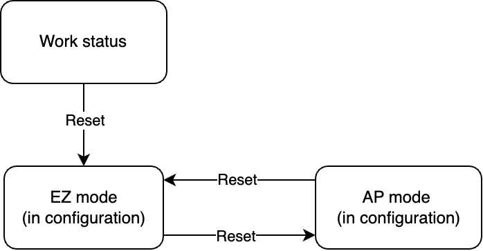
The MCU sends the following data.
| Field | Bytes | Description |
|---|---|---|
| Header | 2 | 0x55aa |
| Version | 1 | 0x00 |
| Command | 1 | 0x03 |
| Data length | 2 | 0x0000 |
| Data | 0 | None |
| Checksum | 1 | Start from the header, add up all the bytes, and then divide the sum by 256 to get the remainder. |
The module returns the following data.
| Field | Bytes | Description |
|---|---|---|
| Header | 2 | 0x55aa |
| Version | 1 | 0x00 |
| Command | 1 | 0x03 |
| Data length | 2 | 0x0000 |
| Data | 0 | None |
| Checksum | 1 | Start from the header, add up all the bytes, and then divide the sum by 256 to get the remainder. |
Example:
- The MCU sends
55 aa 00 03 00 00 02to the module to reset Wi-Fi. - The module returns
55 aa 00 03 00 00 02.
Reset Wi-Fi (selectable pairing mode) (0x04)
- This reset command applies only when you set
nto0in the product information query. - Compared to Reset Wi-Fi (0x03), this command allows the MCU to specify the Wi-Fi pairing mode the module starts in after a reset.
- This command is not supported by keep-alive lock solutions and camera lock solutions.
The MCU sends the following data.
| Field | Bytes | Description |
|---|---|---|
| Header | 2 | 0x55aa |
| Version | 1 | 0x00 |
| Command | 1 | 0x04 |
| Data length | 2 | 0x0001 |
| Data | 1 | When n is set to 0. 0x00: The device enters EZ mode after a reset. 0x01: The device enters AP mode after a reset. |
| Checksum | 1 | Start from the header, add up all the bytes, and then divide the sum by 256 to get the remainder. |
The module returns the following data.
| Field | Bytes | Description |
|---|---|---|
| Header | 2 | 0x55aa |
| Version | 1 | 0x00 |
| Command | 1 | 0x04 |
| Data length | 2 | 0x0000 |
| Data | 0 | None |
| Checksum | 1 | Start from the header, add up all the bytes, and then divide the sum by 256 to get the remainder. |
Example:
- The MCU sends
55 aa 00 04 00 01 01 05to the module to reset the module and start in AP mode. - The module returns
55 aa 00 04 00 00 03.
Notify status of module reset (0x25)
- To use this command, the MCU must enable
bit3ofcapin the response to the product information query (0x01). The module sends the command0x25to the MCU when it is reset. - When the module is reset locally or through the mobile app, it notifies the MCU of the reason for reset, enabling the MCU to act accordingly.
- Scenarios for resetting a device:
- Reset a device locally: The MCU sends a reset command
0x03or0x04to the module. - Remove a device from the mobile app.
- Remove a device from the mobile app and erase the device data. This is a factory reset.
- Clear the local data, but the device is still paired.
- Reset a device locally: The MCU sends a reset command
The module sends the following data.
| Field | Bytes | Description |
|---|---|---|
| Header | 2 | 0x55aa |
| Version | 1 | 0x00 |
| Command | 1 | 0x25 |
| Data length | 2 | 0x0001 |
| Data | 1 | Reason for reset: 0x00: The device is reset locally. 0x01: The device is removed from the app. 0x02: The device is removed from the app, with the device data also erased. 0x03: Local data is erased, but the device is still paired. |
| Checksum | 1 | Start from the header, add up all the bytes, and then divide the sum by 256 to get the remainder. |
The MCU returns the following data.
| Field | Bytes | Description |
|---|---|---|
| Header | 2 | 0x55aa |
| Version | 1 | 0x00 |
| Command | 1 | 0x25 |
| Data length | 2 | 0 |
| Data | - | None |
| Checksum | 1 | Start from the header, add up all the bytes, and then divide the sum by 256 to get the remainder. |
Example:
- The module sends
55 aa 00 25 00 01 01 26to the MCU, indicating that the device is removed from the app. - The MCU returns
55 aa 00 25 00 00 24.
Get the GMT (0x10)
As the international standard of civil time, Greenwich Mean Time (GMT) is independent of the time zone and daylight saving time (DST).
- Door locks are time-sensitive, so make sure to integrate with this command for accurate timing.
- After power on, the device can sync with the time server only after it is connected to the internet. Therefore, the MCU should send this command after receiving network status 5.
- The module might fail to return the GMT due to poor network condition. In this case, the MCU should send the request again to ensure time sync succeeds.
- It is recommended to sync time every time the device is connected to the cloud.
- With the time difference between the GMT and the local time, you can get the time zone where the device is located.
The MCU sends the following data.
| Field | Bytes | Description |
|---|---|---|
| Header | 2 | 0x55aa |
| Version | 1 | 0x00 |
| Command | 1 | 0x10 |
| Data length | 2 | 0x0000 |
| Data | 0 | None |
| Checksum | 1 | Start from the header, add up all the bytes, and then divide the sum by 256 to get the remainder. |
The module returns the following data.
| Field | Bytes | Description |
|---|---|---|
| Header | 2 | 0x55aa |
| Version | 1 | 0x00 |
| Command | 1 | 0x10 |
| Data length | 2 | 0x0008 |
| Data | 8 | Data[0]: indicates whether the time is obtained successfully.
Data[1]: indicates the year. 0x00 indicates the year 2000. Data[2]: indicates the month, ranging from 1 to 12. Data[3]: indicates the day, ranging from 1 to 31. Data[4]: indicates the hour, ranging from 0 to 23. Data[5]: indicates the minute, ranging from 0 to 59. Data[6]: indicates the second, ranging from 0 to 59. Data[7]: indicates the week, ranging from 1 to 7. 1 indicates Monday. Note: Data[7] is meaningless and uses the default value. |
| Checksum | 1 | Start from the header, add up all the bytes, and then divide the sum by 256 to get the remainder. |
Example:
-
The MCU sends
55 aa 00 10 00 00 0Fto the module to request the GMT. -
The module returns
55 aa 00 10 00 08 01 17 02 01 08 09 05 03 65, indicating a successful result and the GMT is:-
08:09:05 on Wednesday, February 1, 2023
-
If the device is in GMT+8 time zone, the local time is 16:09:05 on Wednesday, February 1, 2023.
-
Get local time (0x06)
The local time (the device’s local time) is calculated by adding the time zone offset and DST to the GMT. The time zone is where the device is activated.
The MCU sends the following data.
| Field | Bytes | Description |
|---|---|---|
| Header | 2 | 0x55aa |
| Version | 1 | 0x00 |
| Command | 1 | 0x06 |
| Data length | 2 | 0x0000 |
| Data | 0 | None |
| Checksum | 1 | Start from the header, add up all the bytes, and then divide the sum by 256 to get the remainder. |
The module returns the following data.
| Field | Bytes | Description |
|---|---|---|
| Header | 2 | 0x55aa |
| Version | 1 | 0x00 |
| Command | 1 | 0x06 |
| Data length | 2 | 0x0008 |
| Data | 8 | Data[0]: indicates whether the time is obtained successfully.
0x00 indicates the year 2000. Data[2]: indicates the month, ranging from 1 to 12. Data[3]: indicates the day, ranging from 1 to 31. Data[4]: indicates the hour, ranging from 0 to 23. Data[5]: indicates the minute, ranging from 0 to 59. Data[6]: indicates the second, ranging from 0 to 59. Data[7]: indicates the week, ranging from 1 to 7. 1 indicates Monday. |
| Checksum | 1 | Start from the header, add up all the bytes, and then divide the sum by 256 to get the remainder. |
Example:
- The MCU sends
55 aa 00 06 00 00 05to request the local time. - The module returns
55 aa 00 06 00 08 01 17 02 01 10 09 05 03 49, indicating a successful result and the local time is 16:09:05 on Wednesday, February 1, 2023.
Report real-time status (0x05)
- Status data is directly sent to the cloud, which requires the device to be connected to the cloud. Otherwise, data reporting will fail.
- For more information, see Data point (DP) format (status data unit). Multiple DPs can be reported at the same time.
- Real-time status reporting is triggered in the following situations:
- When the MCU proactively detects status changes of DPs (such as battery level), it reports the changed DP status to the module.
- After the MCU executes the command received from the module, it reports the changed DP status to the module.
- When the MCU receives the DP status query or every time the module gets connected to the cloud, the MCU sends the status of all DPs to the module.
- The DP ID, data type, and payload of the DP that the MCU reports must match the PID’s DP defined on the Tuya Developer Platform. The module returns an error code for invalid status reporting.
The MCU sends the following data.
| Field | Bytes | Description |
|---|---|---|
| Header | 2 | 0x55aa |
| Version | 1 | 0x00 |
| Command | 1 | 0x05 |
| Data length | 2 | It depends on the types and the number of data units. |
| Data | N | Data point (DP) format (status data unit) |
| Checksum | 1 | Start from the header, add up all the bytes, and then divide the sum by 256 to get the remainder. |
The module returns the following data.
| Field | Bytes | Description |
|---|---|---|
| Header | 2 | 0x55aa |
| Version | 1 | 0x00 |
| Command | 1 | 0x05 |
| Data length | 2 | 0x0001 |
| Data | 1 | 0x00: Success. The module receives and reports the status to the cloud. 0x01: Failure. 0x02: Reserved. 0x03: The DP is not configured for the PID. 0x04: DP type error. |
| Checksum | 1 | Start from the header, add up all the bytes, and then divide the sum by 256 to get the remainder. |
Example:
-
Report the status of a single DP: The DP 109 is of Boolean data type, and its value is
1. The MCU sends the following data.55 aa 00 05 00 05 6d 01 00 01 01 79 -
Report the status of multiple DPs:
- The DP 109 is of Boolean data type, and its value is
1. - The DP 102 is of string data type, and its value is 201804121507 that is transferred in ASCII mode. The MCU sends the following data.
55 aa 00 05 00 15 6d 01 00 01 01 66 03 00 0c 32 30 31 38 30 34 31 32 31 35 30 37 5d - The DP 109 is of Boolean data type, and its value is
-
The module returns the following data after it receives and reports the status to the cloud.
55 aa 00 05 00 01 00 05
Report record-type data (0x08)
-
Scenario: The device uses this command to report unlocking records (such as fingerprint unlocking) and alert records (such as failed unlocking attempts) to the cloud to display them on the mobile app.
-
Recommended process: Suppose that a record is generated on a non-keep-alive lock. The MCU powers on the Wi-Fi module and waits for cloud connection. A connection timeout of at least 15 seconds is recommended. The MCU sends the record using command
0x08and waits for a response from the module. If it receives a success response and has no retained data to report, the MCU powers off the module after two seconds. If the cloud connection times out, the MCU can report the record to cache it in the module and power off the module after receiving a success response.- When not connected to the cloud, the module can cache the record-type data with a success response (0x00) to the MCU and send the cached data to the cloud when getting connected.
- The module can cache a maximum of 20 records in a first-in-first-out (FIFO) manner, with a record of up to 80 bytes. When the limit is reached, the newest record will overwrite the oldest one.
- If the module returns
0x01, it indicates the received data is reported successfully, but there is retained data to be reported, the MCU should wait for the module to finish reporting and then power it off after receiving0x00.
-
In case of poor network condition or data congestion, the module might return failure five seconds later. Therefore, it is recommended that the MCU wait at least five seconds for a response from the module.
-
The DP ID, data type, and payload of the DP that the MCU reports must match the PID’s DP defined on the Tuya Developer Platform.
-
Time type
0(use module time) is not recommended. However, if you decide to use this time type, make sure to invoke it after the module gets the time data from the cloud. Otherwise, the recorded time will not be accurate. -
It is unlikely that multiple records occur simultaneously, so it is recommended that lock products report a single record (a status data unit) at a time.
-
The MCU sends the following data.
| Field | Bytes | Description |
|---|---|---|
| Header | 2 | 0x55aa |
| Version | 1 | 0x00 |
| Command | 1 | 0x08 |
| Data length | 2 | It depends on the types and the number of data units. |
| Data | 7 | 7-byte time information of record-type data contains the time type and time data. Data[0]: the time type used to report record-type data.
0x00 indicates the year 2000. Data[2]: indicates the month, ranging from 1 to 12. Data[3]: indicates the day, ranging from 1 to 31. Data[4]: indicates the hour, ranging from 0 to 23. Data[5]: indicates the minute, ranging from 0 to 59. Data[6]: indicates the second, ranging from 0 to 59. |
| Data | N | Data point (DP) format (status data unit) |
| Checksum | 1 | Start from the header, add up all the bytes, and then divide the sum by 256 to get the remainder. |
The module returns the following data.
| Field | Bytes | Description |
|---|---|---|
| Header | 2 | 0x55aa |
| Version | 1 | 0x00 |
| Command | 1 | 0x08 |
| Data length | 2 | 0x0001 |
| Data | 1 | The result of data reporting: 0x00: Success, with no retained data to be reported. 0x01: Success, with retained data to be reported. 0x02: Failure. 0x03: The DP is not configured for the PID. 0x04: DP type error. |
| Checksum | 1 | Start from the header, add up all the bytes, and then divide the sum by 256 to get the remainder. |
Example:
-
Report a single record:
The DP 109 is of Boolean data type, and its value is
1.-
Time type is
0, using the module time.55 aa 00 08 00 0c 00 00 00 00 00 00 00 6d 01 00 01 01 83 -
Time type is
1, using the local time (13:03:29 on April 19, 2018) from the MCU.55 aa 00 08 00 0c 01 12 04 13 0d 03 1d 6d 01 00 01 01 da -
Time type is
2, using the GMT (05:03:29 on April 19, 2018) from the MCU.55 aa 00 08 00 0c 02 12 04 13 05 03 1d 6d 01 00 01 01 d3
-
-
The module returns success, with no retained data to be reported.
55 aa 00 08 00 01 00 08
-
The module returns success, with retained data to be reported.
55 aa 00 08 00 01 01 09
Module sends command (0x09)
-
One command can contain status data units of multiple DPs.
-
After receiving a command, the MCU first responds to
0x09and then executes the command. If needed, the MCU reports the current status of the corresponding DP through the command0x05.Example:
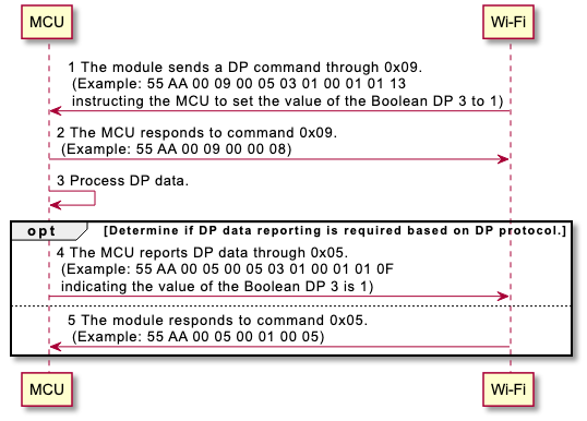
The module sends the following data.
| Field | Bytes | Description |
|---|---|---|
| Header | 2 | 0x55aa |
| Version | 1 | 0x00 |
| Command | 1 | 0x09 |
| Data length | 2 | It depends on the types and the number of data units. |
| Data | N | Data point (DP) format (status data unit) |
| Checksum | 1 | Start from the header, add up all the bytes, and then divide the sum by 256 to get the remainder. |
The MCU returns the following data.
| Field | Bytes | Description |
|---|---|---|
| Header | 2 | 0x55aa |
| Version | 1 | 0x00 |
| Command | 1 | 0x09 |
| Data length | 2 | 0x0000 |
| Data | 0 | None |
| Checksum | 1 | Start from the header, add up all the bytes, and then divide the sum by 256 to get the remainder. |
Example:
- The module sends a command
55 aa 00 09 00 05 03 01 00 01 01 13, instructing the MCU to set the value of the Boolean DP 3 to1. - The MCU returns
55 aa 00 09 00 00 08.
Get cached DP command (0x15)
- Scenario: Non-keep-alive Wi-Fi locks cannot receive DP commands in real time because they are powered off most of the time. The command to set a DP can be cached in the cloud. When the module gets connected, the MCU can request the cached DP command and then act accordingly.
- The MCU can retrieve cached DP commands either by querying all of them or by specifying a specific DP ID.
- Integrate this command if your solution requires caching DP commands. Otherwise, it is not necessary.
The MCU sends the following data.
| Field | Bytes | Description |
|---|---|---|
| Header | 2 | 0x55aa |
| Version | 1 | 0x00 |
| Command | 1 | 0x15 |
| Data length | 2 | N |
| Data | N | Format: dp_num + dp_1 + … + dp_n
|
| Checksum | 1 | Start from the header, add up all the bytes, and then divide the sum by 256 to get the remainder. |
The module returns the following data.
| Field | Bytes | Description |
|---|---|---|
| Header | 2 | 0x55aa |
| Version | 1 | 0x00 |
| Command | 1 | 0x15 |
| Data length | 2 | It depends on the types and the number of data units. |
| Data | - | Format: result + dp_num + data 1 + … + data n
result is 0, there is no following data, and the data length is 1.When dp_num is 0, no cached DP command exists. |
| Checksum | 1 | Start from the header, add up all the bytes, and then divide the sum by 256 to get the remainder. |
Example:
-
The MCU queries the cached DP command of DP 10 and DP 11.
55 AA 00 15 00 03 02 0A 0B 2E -
The module returns the cached command: DP 10 (enable auto lock, Boolean type) and DP 11 (set the auto lock delay to five seconds, value type).
55 AA 00 15 00 0F 01 02 0A 01 00 01 01 0B 02 00 04 00 00 00 05 49 -
The MCU queries the cached command of all DPs.
55 AA 00 15 00 01 00 15 -
The module returns the following data, indicating no cached command exists.
55 AA 00 15 00 02 01 00 17
MCU OTA update
-
All Wi-Fi lock solutions support the OTA update service, allowing you to update the firmware on the module and MCU via OTA.
-
To release major updates or fix critical bugs on delivered products, you can deploy an OTA update on the Tuya Developer Platform.
-
Four update methods are available on the Tuya Developer Platform.
- Update notification: Users receive a firmware update notification on the app and choose whether to install updates.
- Automatic update: Users will not receive any update notification. The module checks for firmware updates within one minute after power-on. If any new version is available, it will automatically pull the updates. The module checks for updates every 24 hours after the first-time power-on.
- Forced update: Users receive a firmware update notification on the app and have no option but to update the firmware.
- Check for updates: Users will not receive a firmware update notification on the app but need to manually check for new updates.
-
The following flowchart shows how the OTA firmware update works.
After the Wi-Fi module has sent all update packets, it will send the command
0x01to request the product information. The MCU must reply with the new MCU software version number within one minute. The new version number should be consistent with that configured on the Tuya Developer Platform. Then, the mobile app can get the result of the update.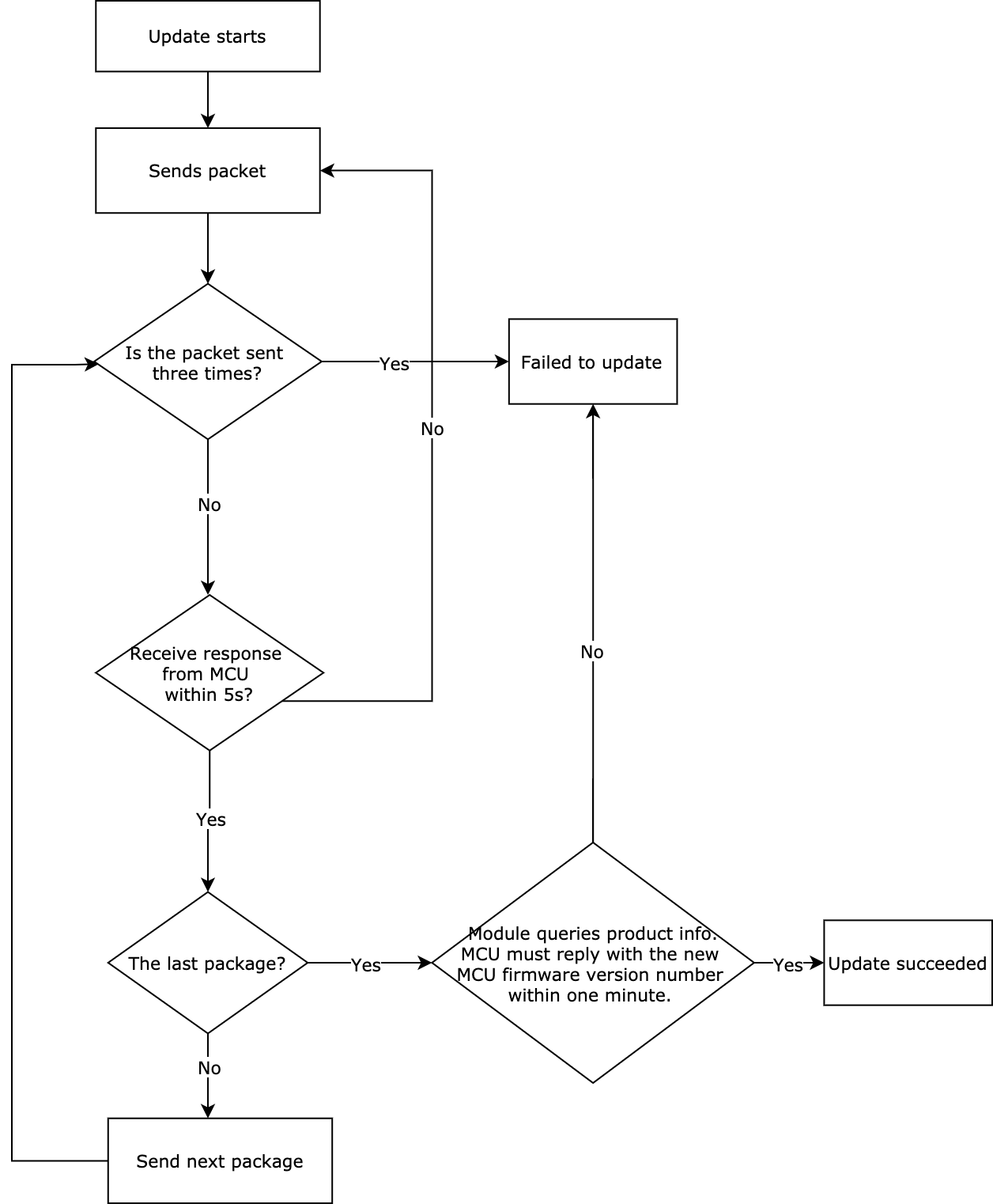
Automatic update (0x21)
-
Typically, the MCU controls the power of the Wi-Fi module. During the update process, the module will notify the MCU of the update status, so that the MCU can power on/off the module accordingly.
-
To use this command, the MCU must set
bit4ofcapto1in the response to the product information query (0x01). Ifbit4is not enabled, the MCU cannot get notified of a firmware update through0x21. In this case, the MCU needs to proactively request firmware updates through0x0Cand0x0D, which is not recommended. -
When you deploy an update for the module or MCU on the Tuya Developer Platform, set the update method to auto update.
-
After the module is powered on and connected to the cloud, it will check for updates. If an update is available, the module sends an update request to the MCU. The MCU responds accordingly.
-
If the MCU accepts the update, the module starts the update. If the update is successful, the module returns success. If an error occurs, the module returns failure.
- With the automatic update feature enabled, the MCU must respond to the command
0x21with update acceptance. Otherwise, the module cannot start the OTA update. - The MCU can power off the module in 15 seconds after getting notified of a successful update installation. During this time, the module connects to the cloud and verifies the firmware version. With successful verification, the mobile app can receive the result of a successful update.
- With the automatic update feature enabled, the MCU must respond to the command
The module sends the following data.
| Field | Bytes | Description |
|---|---|---|
| Header | 2 | 0x55aa |
| Version | 1 | 0x00 |
| Command | 1 | 0x21 |
| Data length | 2 | 0x0002 |
| Data | 2 | Data[0]: The update status.
|
| Checksum | 1 | Start from the header, add up all the bytes, and then divide the sum by 256 to get the remainder. |
The MCU returns the following data.
| Field | Bytes | Description |
|---|---|---|
| Header | 2 | 0x55aa |
| Version | 1 | 0x00 |
| Command | 1 | 0x21 |
| Data length | 2 | 0x0001 |
| Data | 1 | 0x00: The update is accepted. 0x01: The update is rejected due to low battery. 0x02: Other reasons. |
| Checksum | 1 | Start from the header, add up all the bytes, and then divide the sum by 256 to get the remainder. |
Example:
- The module sends
55 aa 00 21 00 02 00 01 23, indicating an MCU firmware update is available. - The MCU returns
55 aa 00 21 00 01 00 21, indicating the update is accepted. - The MCU returns
55 aa 00 21 00 01 01 22, indicating the update is rejected due to low battery.
Initiate update (0x0D)
-
The OTA update can be initiated automatically or manually.
- For automatic updates, when the module detects MCU firmware updates from the cloud, the transmission of the update file automatically starts.
- For manual updates, the module initiates updates only when updates are confirmed on the app.
-
After the update is initiated, the module sends the information about the update (including the size of the firmware update, in bytes) to the MCU. In the response, the MCU can specify the maximum transmission unit (MTU). If not specified, the MTU defaults to 256 bytes.
MD5 checksum applies to modules that support Bluetooth LE + X features.
The module sends the following data.
| Field | Bytes | Description |
|---|---|---|
| Header | 2 | 0x55aa |
| Version | 1 | 0x00 |
| Command | 1 | 0x0d |
| Data length | 2 | 0x0004/0x0024 |
| Data | 4 | Data[0 to 3] (four bytes): The size of the firmware update, in big endian. Data[4 to 35] (32 bytes): The MD5 checksum of the firmware. MD5 field is displayed only when the module supports the Bluetooth LE + X features. |
| Checksum | 1 | Start from the header, add up all the bytes, and then divide the sum by 256 to get the remainder. |
The MCU returns the following data.
| Field | Bytes | Description |
|---|---|---|
| Header | 2 | 0x55aa |
| Version | 1 | 0x00 |
| Command | 1 | 0x0d |
| Data length | 2 | 0x0001 |
| Data | 1 | The MTU:
|
| Checksum | 1 | Start from the header, add up all the bytes, and then divide the sum by 256 to get the remainder. |
Example:
- The module sends
55 aa 00 0d 00 04 00 00 68 00 78, indicating the size of the firmware update is 26,624 bytes. - The MCU returns
55 aa 00 0d 00 01 00 0d, indicating the MTU is set to 256 bytes.
Transfer the update (0x0E)
-
Data format: fragment offset + payload data.
-
When the MCU receives a frame with a length of four bytes and the fragment offset is equal to or greater than the size of the firmware update, the transfer is completed.
The module sends the following data.
| Field | Bytes | Description |
|---|---|---|
| Header | 2 | 0x55aa |
| Version | 1 | 0x00 |
| Command | 1 | 0x0e |
| Data length | 2 | 0x0004 + N |
| Data | 4+N | Data[0 to 3]: The fragment offset, in big endian. Data[4 to n]: The update data. |
| Checksum | 1 | Start from the header, add up all the bytes, and then divide the sum by 256 to get the remainder. |
The MCU returns the following data.
| Field | Bytes | Description |
|---|---|---|
| Header | 2 | 0x55aa |
| Version | 1 | 0x00 |
| Command | 1 | 0x0e |
| Data length | 2 | 0x0000 |
| Data | 0 | None |
| Checksum | 1 | Start from the header, add up all the bytes, and then divide the sum by 256 to get the remainder. |
Example:
-
Assume that the size of the firmware update is 530 bytes.
-
For the first packet, the fragment offset is
0x00000000, and the packet length is 256 bytes.55 aa 00 0e 0104 00000000 xx … xx XX -
For the second packet, the fragment offset is
0x00000100, and the packet length is 256 bytes.55 aa 00 0e 0104 00000100 xx … xx XX -
For the third packet, the fragment offset is
0x00000200, and the packet length is 18 bytes. This is the last fragmented packet.55 aa 00 0e 0016 00000200 xx … xx XX -
For the last packet, the fragment offset is
0x00000212, and the packet length is 0 bytes. The transfer is completed.55 aa 00 0e 0004 00000212 XX
-
-
The MCU should respond to each fragmented packet.
55 aa 00 0e 00 00 0d
Lock password services
Password positional notation (0x1C)
Purpose: Some door locks are not equipped with a 10-key keypad numbered from 0 to 9, but a keypad numbered from 1 to 6. To convert a password into the required form using the base conversion algorithm, the cloud, app panel, and module must be informed of the positional notation being used. The configuration for the cloud and app panel can be set in the product configuration on the Tuya Developer Platform. On the device side, the MCU specifies the positional notation through 0x01C.
Concept: base and starting value.
- Base: indicates the number of unique digits that a keypad has. Base-4 through base-10 are supported.
- Starting value: indicates the keypad starts with 0 or 1.
- Examples:
- If a keypad has five keys numbered 1 through 5, set the base to
5and starting value to1. - If a keypad has six keys numbered 0 through 5, set the base to
6and starting value to0. - If a keypad has nine keys numbered 1 through 9, set the base to
9and starting value to1. - If a keypad has 10 keys numbered 0 through 9, set the base to
10and starting value to0.
- If a keypad has five keys numbered 1 through 5, set the base to
Conversion: The algorithm-based passwords generated in the cloud are in base 10. The lock or the app panel can convert the password into the required base. If the starting value is set to 1, 1 is added to each digit of the converted password. A password can also be converted back to base 10.
Example: A keypad has six keys numbered 1 through 6. The app panel gets a dynamic password 76829103 from the cloud and converts it into 22453525254 for display. When the user enters 22453525254 on the keypad, the MCU sends the entered number to the module through the dedicated command. The module then extracts the original base-10 password 76829103 to compare it with the received password and returns the result to the MCU. The respective side takes care of the conversion logic. The MCU only needs to set the parameters to specify the required positional notation.
List of positional notation:
| Base (number of digits) |
Password starts with 0 or 1 |
Dynamic password |
Offline password |
The min length of online password |
Security level | Multilingual online password |
|---|---|---|---|---|---|---|
| 4 | Configurable | Not supported | Not supported | 8 | 1/29W | Password of 8 to 12 digits |
| 5 | Configurable | Supported | Not supported | 8 | 1/39W | Password of 8 to 12 digits |
| 6 | Configurable | Supported | Not supported | 8 | 1/100W | Password of 8 to 12 digits |
| 7 | Configurable | Supported | Supported | 8 | 1/100W | Password of 8 to 11 digits |
| 8 | Configurable | Supported | Supported | 7 | 1/100W | Password of 7 to 11 digits |
| 9 | Configurable | Supported | Supported | 7 | 1/100W | Password of 7 to 10 digits |
| 10 | Not configurable | Supported | Supported | 6 | 1/100W | Password of 6 to 10 digits |
- You must set the positional notation after the product information query (0x01) and before any password-related operation.
- If you specify the positional notation through the command
0x1C, you must use the new version of command0x14. - If not specified, the default base is 10. The positional notation configuration is stored in the non-volatile memory, so the MCU only needs to set it once.
The MCU sends the following data.
| Field | Bytes | Description |
|---|---|---|
| Header | 2 | 0x55aa |
| Version | 1 | 0x00 |
| Command | 1 | 0x1C |
| Data length | 2 | 0x0002 |
| Data | 2 | Data[0]: The base, ranging from 4 to 10. Data[1]: The starting value, 0 or 1. |
| Checksum | 1 | Start from the header, add up all the bytes, and then divide the sum by 256 to get the remainder. |
The module returns the following data.
| Field | Bytes | Description |
|---|---|---|
| Header | 2 | 0x55aa |
| Version | 1 | 0x00 |
| Command | 1 | 0x1C |
| Data length | 2 | 0x0001 |
| Data | 1 | The result. 0x00: Success. Other values: Failure. |
| Checksum | 1 | Start from the header, add up all the bytes, and then divide the sum by 256 to get the remainder. |
Example:
- The MCU sends 55 aa 00 1c 00 02 05 01 23 to the module, indicating the base is 5 and the starting value is 1 for a 5-key keypad numbered 1 through 5.
- The module returns
55 aa 00 1c 00 01 00 1c, indicating success.
Request temporary password (legacy 0x14)
Scenario: A temporary password is stored in the cloud and can be generated when a lock is not connected to the cloud. When the user enters a password to unlock the door, if the MCU determines that this is not a local password, it sends the module a command based on the password length for authentication.
-
The cloud sends full temporary passwords to the lock. The MCU should update and store all the temporary passwords accordingly.
-
The user can set the start and end time of a temporary password and schedule weekly recurring access.
-
Password ID: The ID of a cloud-generated temporary password is
900 + x(xranges from 0 to 50). A temporary password that the lock pulls from the cloud carries thex. When reporting the unlocking record of the temporary password, the lock should use the actual ID900 + xso that the cloud can identify the temporary password. -
The start and end date and time is in GMT and consists of year, month, day, hour, minute, and second.
-
The start and end time of the day for recurring access is in HH:MM, GMT.
-
Recurring access: The user can only create one recurring schedule for a temporary password that is created on the app panel.
-
Up to 10 temporary passwords can be created for non-keep-alive locks. The keep-alive lock stays connected to the cloud, so the temporary password is sent to the lock directly. In case of offline status, the temporary password is cached in the cloud. The keep-alive lock pulls it in DP format through
0x1Dafter getting online. -
Determining the validity period of a temporary password relies on the clock’s accuracy. It is recommended to sync time every time the device is connected to the cloud, or equip a timekeeping chip and backup battery.
The legacy
0x14command does not support configuring positional notation. The length of a temporary password is fixed to 7 digits. Current solutions do not use the legacy0x14command but use the new0x14instead to pull the temporary password.
The MCU sends the following data.
| Field | Bytes | Description |
|---|---|---|
| Header | 2 | 0x55aa |
| Version | 1 | 0x00 |
| Command | 1 | 0x14 |
| Data length | 2 | 0x0000 |
| Data | 0 | None |
| Checksum | 1 | Start from the header, add up all the bytes, and then divide the sum by 256 to get the remainder. |
The module returns the following data.
| Field | Bytes | Description |
|---|---|---|
| Header | 2 | 0x55aa |
| Version | 1 | 0x00 |
| Command | 1 | 0x14 |
| Data length | 2 | 1/N |
| Data | 1/N | Data[0]: indicates whether the temporary password is obtained successfully.
If the number of passwords is 0, it indicates no password is created and there is no following password data. Data[2]: the password length (N). Data[3]: packet fragmentation flag and packet sequence number.
Data[4]: the password ID (900 + x) Data[5]: access times. 0: unlimited times. 1: one time. Data[6]: password status. 0: valid. 1: invalid. (The password has been deleted) Data[7 to 12]: the start date and time of the password. Data[13 to 18]: the end date and time of the password. The date and time format: year, month, day, hour, minute, second, in GMT. Data[19 to19+N-1]: the temporary password in ASCII mode. Data[19+N]: the recurring schedule (up to one schedule can be created currently). Data[20+N]: specifies whether the password is valid all day long. 0: valid within the specified period of a day. 1: valid all day long. Data[21+N]: the start time (hour) Data[22+N]: the start time (minute) Data[23+N]: the end time (hour) Data[24+N]: the end time (minute) The start and end time format: HH:MM, in GMT. Data[25+N]: the weekly schedule. See Encoding for a weekly schedule.
… // Data of the nth temporary password … |
| Checksum | 1 | Start from the header, add up all the bytes, and then divide the sum by 256 to get the remainder. |
Example:
-
The lock pulls the cached temporary password, using the legacy command that does not support positional notation.
55 aa 00 14 00 00 13 -
The module returns the temporary password data:
55 aa 00 14 00 21 01 01 07 00 0A 00 00 14 0A 09 01 31 19 14 0A 0D 02 31 19 38 30 32 34 33 36 36 01 00 00 00 01 00 3E DD-
01 // The result: success
-
01 // The number of passwords: one
-
07 // The password length: 7
-
00 // The sequence number of the packet is 0, and there is no subsequent packet. (Bit7: indicates whether there is a subsequent packet. Bit 6 to bit 0: the sequence number of the current packet, starting from 0.)
// Data of the first temporary password.
-
0A // The password ID is 10. You need to add 900 to the password ID to get the actual ID.
-
00 // The access times. (
0: unlimited times within the validity period.1: one time within the validity period.) -
00 // The password status. (
0: valid.1: invalid.) -
14 0A 09 01 31 19 // The start date and time in GMT, indicating 09:49 on October 9, 2020, in GMT+8.
-
14 0A 0D 02 31 19 // The end date and time in GMT, indicating10:49 on October 13, 2020, in GMT+8.
-
38 30 32 34 33 36 36 // The password in ASCII format, corresponding to 8024366.
// The recurring schedule.
-
01 // The number of schedules. (Currently, up to one schedule can be created.)
-
00 // The password is valid within the specified period of a day. (
1: indicates the password is valid all day long and the following start and end time data is invalid.) -
00 // The start time (hour)
-
00 // The start time (minute)
-
01 // The end time (hour)
-
00 // The end time (minute)
-
3E // A weekly schedule:
0011 1110, indicating the schedule repeats every week Monday through Friday. Bit 0: Sunday. Bit 1: Monday. Bit 2: Tuesday. Bit 3: Wednesday. Bit 4: Thursday. Bit 5: Friday. Bit 6: Saturday.
-
Request temporary password (new 0x14)
Scenario: A temporary password is stored in the cloud and can be generated when a lock is not connected to the cloud. When the user enters a password to unlock the door, if the MCU determines that this is not a local password, it sends the module a command based on the password length for authentication.
- The cloud sends full temporary passwords to the lock. The MCU should update and store all the temporary passwords accordingly.
- The user can set the start and end time of a temporary password and schedule weekly recurring access.
- Password ID: The ID of a cloud-generated temporary password is
900 + x(xranges from 0 to 50). A temporary password that the lock pulls from the cloud carries thex. When reporting the unlocking record of the temporary password, the lock should use the actual ID900 + xso that the cloud can identify the temporary password. - The start and end date and time is in GMT and consists of year, month, day, hour, minute, and second.
- The start and end time of the day for recurring access is in HH:MM, GMT.
- Recurring access: The user can only create one recurring schedule for a temporary password that is created on the app panel.
- Up to 10 temporary passwords can be created for non-keep-alive locks. The keep-alive lock stays connected to the cloud, so the temporary password is sent to the lock directly. In case of offline status, the temporary password is cached in the cloud. The keep-alive lock pulls it in DP format through
0x1Dafter getting online. - Determining the validity period of a temporary password relies on the clock’s accuracy. It is recommended to sync time every time the device is connected to the cloud, or equip a timekeeping chip and backup battery.
- This new command supports positional notation and can replace the legacy command functionally. We recommend you choose this new command.
The MCU sends the following data.
| Field | Bytes | Description |
|---|---|---|
| Header | 2 | 0x55aa |
| Version | 1 | 0x00 |
| Command | 1 | 0x14 |
| Data length | 2 | 0x0000 |
| Data | 0 | None |
| Checksum | 1 | Start from the header, add up all the bytes, and then divide the sum by 256 to get the remainder. |
The module returns the following data.
| Field | Bytes | Description |
|---|---|---|
| Header | 2 | 0x55aa |
| Version | 1 | 0x00 |
| Command | 1 | 0x14 |
| Data length | 2 | 1/N |
| Data | 1/N | Data[0]: indicates whether the temporary password is obtained successfully.
Data[2]: packet fragmentation flag and packet sequence number.
Data[3]: the password length (N). Data[4]: the password ID (900 + x) Data[5]: access times. 0: unlimited times. 1: one time. Data[6]: password status. 0: valid. 1: invalid. (The password has been deleted) Data[7 to 12]: the start date and time of the password. Data[13 to 18]: the end date and time of the password. The date and time format: year, month, day, hour, minute, second, in GMT. Data[19 to19+N-1]: the temporary password in ASCII mode. Data[19+N]: the recurring schedule (up to one schedule can be created currently). Data[20+N]: specifies whether the password is valid all day long. 0: valid within the specified period of a day. 1: valid all day long. Data[21+N]: the start time (hour) Data[22+N]: the start time (minute) Data[23+N]: the end time (hour) Data[24+N]: the end time (minute) The start and end time format: HH:MM, in GMT. Data[25+N]: the weekly schedule. See Encoding for a weekly schedule.
… // Data of the nth temporary password … |
| Checksum | 1 | Start from the header, add up all the bytes, and then divide the sum by 256 to get the remainder. |
Example:
-
The lock pulls the cached temporary password, using the new command that supports positional notation.
55 aa 00 14 00 00 13 -
The module returns the temporary password data:
55 aa 00 14 00 21 01 01 00 07 0A 00 00 14 0A 09 01 31 19 14 0A 0D 02 31 19 38 30 32 34 33 36 36 01 00 00 00 01 00 3E DD-
01 // The result: success
-
01 // The number of passwords: one
-
00 // The sequence number of the packet is 0, and there is no subsequent packet. (Bit7: indicates whether there is a subsequent packet. Bit 6 to bit 0: the sequence number of the current packet, starting from 0.)
// Data of the first temporary password.
-
07 // The password length: 7
-
0A // The password ID is 10. You need to add 900 to the password ID to get the actual ID.
-
00 // The access times. (
0: unlimited times within the validity period.1: one time within the validity period.) -
00 // The password status. (
0: valid.1: invalid.) -
14 0A 09 01 31 19 // The start date and time in GMT, indicating 09:49 on October 9, 2020, in GMT+8.
-
14 0A 0D 02 31 19 // The end date and time in GMT, indicating10:49 on October 13, 2020, in GMT+8.
-
38 30 32 34 33 36 36 // The password in ASCII format, corresponding to 8024366.
// The recurring schedule of the first temporary password.
-
01 // The number of schedules. (Currently, up to one schedule can be created.)
-
00 // The password is valid within the specified period of a day. (
1: indicates the password is valid all day long and the following start and end time data is invalid.) -
00 // The start time (hour)
-
00 // The start time (minute)
-
01 // The end time (hour)
-
00 // The end time (minute)
-
3E // A weekly schedule:
0011 1110, indicating the schedule repeats every week Monday through Friday. Bit 0: Sunday. Bit 1: Monday. Bit 2: Tuesday. Bit 3: Wednesday. Bit 4: Thursday. Bit 5: Friday. Bit 6: Saturday.
-
Request to compare dynamic passwords (0x12)
- The lock and the cloud have an identical set of algorithms stored to generate dynamic passwords, with the only difference in the Unix timestamp. If the Unix timestamp offset between the clock and the cloud is less than five minutes, it is considered that the dynamic password generated by the lock and the cloud is identical.
- It is not recommended to apply this command to dynamic passwords. You can use the command
0x16instead if your module is applicable. This command is supported by WBRL module only. See Protocol support.
The MCU sends the following data.
| Field | Bytes | Description |
|---|---|---|
| Header | 2 | 0x55aa |
| Version | 1 | 0x00 |
| Command | 1 | 0x12 |
| Data length | 2 | N |
| Data | N | Data format: Time in GMT and the password data. Data[0 to 5]: Year, month, day, hour, minute, and second in GMT. Data[6 to 13]: The password the user enters, in ASCII format. Valid values: 0 to 9. Data[14]: Defaults to 0x00. |
| Checksum | 1 | Start from the header, add up all the bytes, and then divide the sum by 256 to get the remainder. |
The module returns the following data.
| Field | Bytes | Description |
|---|---|---|
| Header | 2 | 0x55aa |
| Version | 1 | 0x00 |
| Command | 1 | 0x12 |
| Data length | 2 | 0x0001 |
| Data | 1 | 0x00: Success. 0x01: Failure. 0x02: The device is not activated. 0x03: Data length error. |
| Checksum | 1 | Start from the header, add up all the bytes, and then divide the sum by 256 to get the remainder. |
Example:
-
The MCU requests to compare the dynamic password
41833832entered at 03:45:07 on September 22, 2020, with the one in the cloud.55 AA 00 12 00 0F 14 09 16 03 2D 07 34 31 38 33 33 38 33 32 00 2A -
The module returns success.
55 AA 00 12 00 01 00 12
Request to compare algorithm passwords (dynamic/offline) (0x16)
-
Scenario: The user generates an algorithm password on the app panel. The visitor enters the password within the validity period to unlock the door. The creation and use of an algorithm password (dynamic/offline) does not rely on internet access. The algorithm password depends on time factors, which requires the accuracy of the MCU’s clock to authenticate an offline password.
-
Recommended process: When the user enters an offline password to unlock the door, if the MCU determines that this is not a local password, it sends the module the command
0x16based on the password length (generally at least eight digits) for authentication. The module runs the algorithm based on the received timestamp and password content and returns the authentication result, password type, and encoding data. If the authentication succeeds, the MCU reports the unlocking or operation record based on the received password type and encoding data. -
Description of dynamic passwords:
The lock and the cloud have an identical set of algorithms stored to generate dynamic passwords, with the only difference in the Unix timestamp. If the Unix timestamp offset between the clock and the cloud is less than five minutes, it is considered that the dynamic password generated by the lock and the cloud is identical.
-
Description of offline passwords:
-
One-time password: It can be used only once with a validity period of six hours and takes effect immediately after creation. Up to 10 one-time passwords are available every hour on the hour.
-
Time-limited password: It can be used unlimited times within the specified start and end time during the validity period of up to one year. The time-limited password must be used at least once within 24 hours after it takes effect. Otherwise, it will expire. A lock can only get one time-limited password of the same start and end time.
-
Clear code (delete an offline password): When the user deletes a time-limited password on the mobile app, the lock will get a clear code to delete the corresponding password. A clear code only applies to a time-limited offline password that has been used at least once.
Non-keep-alive lock solutions do not support the clear code that empties all offline passwords, so the
typeof the offline password in the return data does not identify the types of clear code. -
Clear code (empty all offline passwords): It is valid for 24 hours and used to delete all offline passwords.
Keep-alive camera lock solutions support both types of clear code, so the
typeof the offline password in the return data identifies the types of clear code.
-
-
Module support: Only the WBRL module can apply the command
0x16to both the dynamic and offline passwords. Other modules use the command0x12for dynamic passwords. For more information, see Protocol support.
The MCU sends the following data.
| Field | Bytes | Description |
|---|---|---|
| Header | 2 | 0x55aa |
| Version | 1 | 0x00 |
| Command | 1 | 0x16 |
| Data length | 2 | N |
| Data | N | Data format: Time in GMT, the password length, and the password. Data[0 to 5]: Year, month, day, hour, minute, and second in GMT. Data[6]: The password length. Data[7 to N]: The password content in decimal, non-ASCII. |
| Checksum | 1 | Start from the header, add up all the bytes, and then divide the sum by 256 to get the remainder. |
The module returns the following data.
| Field | Bytes | Description |
|---|---|---|
| Header | 2 | 0x55aa |
| Version | 1 | 0x00 |
| Command | 1 | 0x16 |
| Data length | 2 | N |
| Data | N | Data format: result + type + decode_len + decode Data[0]: result, indicating the comparison result.
type, indicating the type of the offline password.
decode_len, indicating the length of the decoded data. Data[3 to n]: decode, indicating the decoded data.1. The decoded data is used to report the record of the offline password. |
| Checksum | 1 | Start from the header, add up all the bytes, and then divide the sum by 256 to get the remainder. |
Example:
-
The MCU requests to compare the offline password
4183383233entered at 03:45:07 on September 22, 2020, with the one in the cloud.55 AA 00 16 00 11 14 09 16 03 2D 07 0A 04 01 08 03 03 08 03 02 03 03 C0 -
The module returns the result.
55 AA 00 16 00 13 00 01 10 34 7B 6E BD 51 C8 73 03 FE D6 87 0D 5E A9 9B C5 71- Comparison result: 0x00, indicting success.
- The password type: 0x01, indicating a one-time password.
- The length of the decoded data: 16 bytes.
- The decoded data: 34 7B 6E BD 51 C8 73 03 FE D6 87 0D 5E A9 9B C5. The MCU uses it to report the record.
Keep-alive solution specific features
Sync time (comprehensive info) (0x1B)
The MCU can use this command to request the comprehensive information about the current date and time, including timestamp, time zone, and daylight saving time (DST). For more information about the compatible time parameter, see Protocol support.
The MCU sends the following data.
| Field | Bytes | Description |
|---|---|---|
| Header | 2 | 0x55aa |
| Version | 1 | 0x00 |
| Command | 1 | 0x1B |
| Data length | 2 | 0x0000 |
| Data | 0 | None |
| Checksum | 1 | Start from the header, add up all the bytes, and then divide the sum by 256 to get the remainder. |
The module returns the following data.
| Field | Bytes | Description |
|---|---|---|
| Header | 2 | 0x55aa |
| Version | 1 | 0x00 |
| Command | 1 | 0x1B |
| Data length | 2 | 0x0011 |
| Data | 17 | Data is 17 bytes long, in the following format. Data[0]: indicates whether the time is obtained successfully.
Data[5]: Indicates whether the time zone is obtained successfully.
0x08, and for UTC-03:00, it is 0x03.Data[8]: Specifies whether DST is in effect.
Data[13] to Data[16]: The timestamp when DST ends, in big endian. |
| Checksum | 1 | Start from the header, add up all the bytes, and then divide the sum by 256 to get the remainder. |
Example:
The MCU sends 55 aa 00 1B 00 00 1A to the module to request the comprehensive information about the current date and time.
The module returns 55 aa 00 1B 00 11 01 63 DA 1E 21 01 00 08 00 00 00 00 00 00 00 00 00 B1 , as described below.
-
The Unix timestamp
0x63DA1E21(1675238945in decimal) is obtained, indicating the time is 08:09:05 on February 1, 2023. -
The time zone is GMT+8.
-
The DST is not in effect.
-
Given this, the local time is 16:09:05 on February 1, 2023.
Request temporary password in DP format (0x1D)
- Typically, the keep-alive lock stays connected to the cloud over MQTT, so operations on the temporary password can be sent to the lock directly through the DP command. When the lock is disconnected, users can create, modify, and delete a temporary password. The action will be cached in the cloud, with up to 10 passwords allowed to be stored. When the module reconnects, the MCU can send the command
0x1Dto instruct the module to fetch the data cached in the cloud during disconnection. To facilitate processing data (received through DP commands or pulled through0x1D) on the MCU side, the core data of this command follows the DP protocol. - After receiving the data returned by the command
0x1D, the MCU parses each temporary password according to the protocol and checks if the password exists locally based on the cloud ID.- If a temporary password exists, it will be updated and saved.
- If a temporary password does not exist, it will be created. The creation result is returned through the DP of adding a temporary password.
- This command is only supported by keep-alive Wi-Fi lock solutions.
The MCU sends the following data.
| Field | Bytes | Description |
|---|---|---|
| Header | 2 | 0x55aa |
| Version | 1 | 0x00 |
| Command | 1 | 0x1D |
| Data length | 2 | 0x0000 |
| Data | 0 | None |
| Checksum | 1 | Start from the header, add up all the bytes, and then divide the sum by 256 to get the remainder. |
The module returns the following data.
| Field | Bytes | Description |
|---|---|---|
| Header | 2 | 0x55aa |
| Version | 1 | 0x00 |
| Command | 1 | 0x1D |
| Data length | 2 | 1/N |
| Data | 1/N | Data[0]: indicates whether the temporary password is obtained successfully.
// Data of the first temporary password Data[3 to 4]: the password ID in the cloud. Data[5]: password status. 0: invalid. 1: valid. 2: deleted. Data[6 to 22]: validity period. See Appendix 2: Validity period Data[23]: access times. 0: unlimited times. 1: one time. Data[24]: the password length. Data[25 to n.]: the password content in decimal, non-ASCII. // Data of the second temporary password. … // Data of the nth temporary password. … |
| Checksum | 1 | Start from the header, add up all the bytes, and then divide the sum by 256 to get the remainder. |
Example:
-
Get cached temporary password in DP format
55 aa 00 1D 00 00 1C -
The module returns the temporary password data:
55 aa 00 1D 00 20 01 01 01 00 02 01 5A 6A 6F 80 5B 6A 4D D0 02 00 00 00 3E 08 00 08 1E 00 07 03 08 03 02 06 05 01 68-
01 // The result: success
-
01 // The number of packets: One packet.
-
01 // The sequence number of the packet: 1 (the sequence starts from 1 by default).
-
00 02 // The password ID assigned in the cloud: 2
-
01 // The password status (0: invalid. 1: valid. 2: deleted.)
-
5A 6A 6F 80 5B 6A 4D D0 02 00 00 00 3E 08 00 08 1E // The validity period, 17 bytes long.
- 5A 6A 6F 80 // The start date and time, in GMT. The timestamp is
1516924800, indicating 08:00:00 on January 26, 2018. - 5B 6A 4D D0 // The end date and time, in GMT. The timestamp is
1533693392, indicating 09:56:32 on August 8, 2018. - 02 // The recurring pattern: Weekly schedule
- 00 00 00 3E // The days of the week when this schedule repeats: Monday through Friday
- 08 00 // The start time of the day: 08:00
- 08 1E // The end time of the day: 08:30
- 5A 6A 6F 80 // The start date and time, in GMT. The timestamp is
-
00 // The access times. (
0: unlimited times within the validity period.1: one time within the validity period.) -
07 // The password length: 7 digits
-
03 08 03 02 06 05 01 // The password content, corresponding to
3832651.
-
Time parameters for deep sleep (0x80)
- To use this command, the MCU should set
bit5ofcapin the response to the product information query (0x01).- If
bit5is set to0, deep sleep is implemented on the module side. The MCU does not need to implement this command. When the user sets the on/off state and time period on the app panel, the module does not send the time parameters to the MCU through0x80. The module enters deep sleep mode when the specified time elapses, and then runs in a keep-alive state upon waking up. - If
bit5is set to1, deep sleep is implemented on the MCU side. When the user sets the on/off state and time period on the app panel, the module sends the time parameters to the MCU through0x80. The MCU determines when to enter and exit deep sleep mode. The module does not implement any logic.
- If
- It is recommended to set
bit5to0.
The module sends the following data.
| Field | Bytes | Description |
|---|---|---|
| Header | 2 | 0x55aa |
| Version | 1 | 0x00 |
| Command | 1 | 0x80 |
| Data length | 2 | 0x0009 |
| Data | 9 | Data[0]: Specifies whether to enable deep sleep mode.
Data[3 to 4]: The time to exit sleep mode, in HH:MM. Data[5 to 8]: Reserved. |
| Checksum | 1 | Start from the header, add up all the bytes, and then divide the sum by 256 to get the remainder. |
The MCU returns the following data.
| Field | Bytes | Description |
|---|---|---|
| Header | 2 | 0x55aa |
| Version | 1 | 0x00 |
| Command | 1 | 0x80 |
| Data length | 2 | 0 |
| Data | 0 | None |
| Checksum | 1 | Start from the header, add up all the bytes, and then divide the sum by 256 to get the remainder. |
Example:
-
The module sends the sleep time parameter
55 aa 00 80 00 09 01 16 00 07 00 00 00 00 00 B0to the MCU, indicating sleep mode is enabled, with a sleep period from 22:00 to 07:00. -
The MCU returns
55 aa 00 80 00 00 7F.
Screen-on time control (T31) (0x83)
- To use this command, the MCU should set
bit8ofcapin the response to the product information query (0x01).- 0: Control through pin interrupt.
- 1: Control through serial command.
- The T31 camera lock cannot enter sleep mode when UVC screen driver is used. In this case, this command can be applied to control the sleep mode.
The MCU sends the following data.
| Field | Bytes | Description |
|---|---|---|
| Header | 2 | 0x55aa |
| Version | 1 | 0x00 |
| Command | 1 | 0x83 |
| Data length | 2 | 0x0001 |
| Data | 1 | 0x00: Allow sleep. 0x01: Not allow sleep when the screen is on. The default screen timeout on the module is 10 minutes. |
| Checksum | 1 | Start from the header, add up all the bytes, and then divide the sum by 256 to get the remainder. |
The module returns the following data.
| Field | Bytes | Description |
|---|---|---|
| Header | 2 | 0x55aa |
| Version | 1 | 0x00 |
| Command | 1 | 0x83 |
| Data length | 2 | 0x0001 |
| Data | 1 | 0x00: Success. 0x01: Failure. |
| Checksum | 1 | Start from the header, add up all the bytes, and then divide the sum by 256 to get the remainder. |
Example:
- The MCU sends
55 aa 00 83 00 01 00 83to the module, allowing for sleep mode. - The module returns
55 aa 00 83 00 01 00 83, indicating success.
Enable power-on pairing (0x84)
-
If not paired, the keep-alive lock (using the T31 or WBRL module) automatically enters pairing mode when powered on. This command allows you to enable or disable power-on pairing as needed.
-
To use this command, the MCU should set
bit9ofcapto1in the response to the product information query (0x01).-
If you want to keep the power-on pairing feature as is, implementing this command is not necessary.
-
If you want to disable power-on pairing and trigger pairing manually, set
bit9incapto1and implement this command.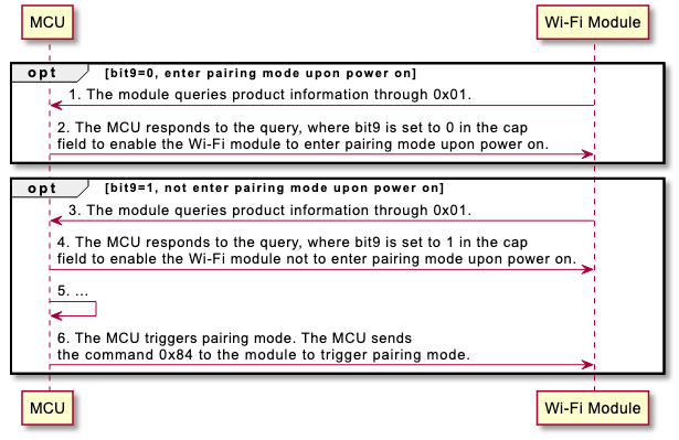
-
@startuml opt bit9=0, enter pairing mode upon power on MCU <- "Wi-Fi Module": 1. The module queries product information through 0x01. MCU -> "Wi-Fi Module": 2. The MCU responds to the query, where bit9 is set to 0 in the cap \nfield to enable the Wi-Fi module to enter pairing mode upon power on. end opt bit9=1, not enter pairing mode upon power on MCU <- "Wi-Fi Module": 3. The module queries product information through 0x01. MCU -> "Wi-Fi Module": 4. The MCU responds to the query, where bit9 is set to 1 in the cap \nfield to enable the Wi-Fi module not to enter pairing mode upon power on. MCU -> MCU: 5. ... MCU -> "Wi-Fi Module": 6. The MCU triggers pairing mode. The MCU sends \nthe command 0x84 to the module to trigger pairing mode. end @enduml
The MCU sends the following data.
| Field | Bytes | Description |
|---|---|---|
| Header | 2 | 0x55aa |
| Version | 1 | 0x00 |
| Command | 1 | 0x84 |
| Data length | 2 | 0x0001 |
| Data | 1 | 0x00: Disable. The lock does not enter pairing mode when powered on. 0x01: Enable. The lock enters pairing mode when powered on. |
| Checksum | 1 | Start from the header, add up all the bytes, and then divide the sum by 256 to get the remainder. |
The module returns the following data.
| Field | Bytes | Description |
|---|---|---|
| Header | 2 | 0x55aa |
| Version | 1 | 0x00 |
| Command | 1 | 0x84 |
| Data length | 2 | 0x0001 |
| Data | 1 | 0x00: Success. 0x01: Failure. |
| Checksum | 1 | Start from the header, add up all the bytes, and then divide the sum by 256 to get the remainder. |
Example:
- The MCU sends
55 aa 00 84 00 01 00 84to the module to disable power-on pairing. - The module returns
55 aa 00 84 00 01 00 84, indicating success.
Set default parameters of the module (0x85)
In the WXU keep-alive solution, the lock PCB can use this command to change the settings of certain default parameters. For example, the time of deep sleep and the keep-alive Delivery Traffic Indication Message (DTIM) time.
The following parameter can be set:
dtm: 0 specifies DTIM 10, and 1 specifies DTIM 20.
The MCU sends the following data.
| Field | Bytes | Description |
|---|---|---|
| Header | 2 | 0x55aa |
| Version | 1 | 0x00 |
| Command | 1 | 0x85 |
| Data length | 2 | N |
| Data | N | The setting information (multiple parameters can be set later). See the description below. |
| Checksum | 1 | Start from the header, add up all the bytes, and then divide the sum by 256 to get the remainder. |
Example of setting information:
{"dtm":0}
The module returns the following data.
| Field | Bytes | Description |
|---|---|---|
| Header | 2 | 0x55aa |
| Version | 1 | 0x00 |
| Command | 1 | 0x85 |
| Data length | 2 | 0x0001 |
| Data | 1 | 0x00: Success 0x01: Failure |
| Checksum | 1 | Start from the header, add up all the bytes, and then divide the sum by 256 to get the remainder. |
Transmit raw data (0x90)
Transmit raw data between the lock PCB and the peephole camera.
The MCU sends the following data.
| Field | Bytes | Description |
|---|---|---|
| Header | 2 | 0x55aa |
| Version | 1 | 0x00 |
| Command | 1 | 0x90 |
| Data length | 2 | N |
| Data | N | Custom information, not parsed by the module |
| Checksum | 1 | Start from the header, add up all the bytes, and then divide the sum by 256 to get the remainder. |
The module does not proactively reply.
Start raw data transmission (0x91)
Start or stop raw data transmission between the lock PCB and the peephole camera.
The MCU sends the following data.
| Field | Bytes | Description |
|---|---|---|
| Header | 2 | 0x55aa |
| Version | 1 | 0x00 |
| Command | 1 | 0x91 |
| Data length | 2 | 1 |
| Data | 1 |
|
| Checksum | 1 | Start from the header, add up all the bytes, and then divide the sum by 256 to get the remainder. |
The module returns the following data.
| Field | Bytes | Description |
|---|---|---|
| Header | 2 | 0x55aa |
| Version | 1 | 0x00 |
| Command | 1 | 0x91 |
| Data length | 2 | 1 |
| Data | 1 |
|
| Checksum | 1 | Start from the header, add up all the bytes, and then divide the sum by 256 to get the remainder. |
Extended services
Query signal strength of the connected router (0x0B)
- The MCU can query the signal strength of the connected router through this command.
- The query must be sent after the network status becomes status 4 (the Wi-Fi network is set up, and the device is connected to the router). Otherwise, the module will return failure.
The MCU sends the following data.
| Field | Bytes | Description |
|---|---|---|
| Header | 2 | 0x55aa |
| Version | 1 | 0x00 |
| Command | 1 | 0x0b |
| Data length | 2 | 0x0000 |
| Data | 0 | None |
| Checksum | 1 | Start from the header, add up all the bytes, and then divide the sum by 256 to get the remainder. |
The module returns the following data.
| Field | Bytes | Description |
|---|---|---|
| Header | 2 | 0x55aa |
| Version | 1 | 0x00 |
| Command | 1 | 0x0b |
| Data length | 2 | 0x0002 |
| Data | 2 | Data[0]: The query result.
|
| Checksum | 1 | Start from the header, add up all the bytes, and then divide the sum by 256 to get the remainder. |
Example:
- The MCU sends
55 aa 00 0b 00 00 0Ato the module to query the signal strength of the connected router. - The module returns
55 aa 00 0b 00 02 01 50 5D, indicating the signal strength is 80.
Report serial number of MCU (0x17)
The MCU reports its serial number to the module through this command.
The MCU sends the following data.
| Field | Bytes | Description |
|---|---|---|
| Header | 2 | 0x55aa |
| Version | 1 | 0x00 |
| Command | 1 | 0x17 |
| Data length | 2 | N |
| Data | - | Format: the length of the serial number (one byte) and the serial number (n bytes) Note that the length of the serial number cannot exceed 32 bytes. |
| Checksum | 1 | Start from the header, add up all the bytes, and then divide the sum by 256 to get the remainder. |
The module returns the following data.
| Field | Bytes | Description |
|---|---|---|
| Header | 2 | 0x55aa |
| Version | 1 | 0x00 |
| Command | 1 | 0x17 |
| Data length | 2 | 1 |
| Data | 1 | The result.
|
| Checksum | 1 | Start from the header, add up all the bytes, and then divide the sum by 256 to get the remainder. |
Example:
- The MCU reports the serial number
55 aa 00 17 00 09 08 41 42 43 44 31 32 33 34 FBto the platform ABCD1234. - The module returns
55 aa 00 17 00 01 00 17, indicating success.
MCU power-off notification (0x22)
The MCU notifies the module of powering off before proceeding. The module will proactively disconnect from the router to improve the success rate of reconnection.
To accommodate the performance of different MCUs, the module will respond three times. The MCU can power off on receiving the first response.
This command applies to non-keep-alive locks that power off when needed.
The MCU sends the following data.
| Field | Bytes | Description |
|---|---|---|
| Header | 2 | 0x55aa |
| Version | 1 | 0x00 |
| Command | 1 | 0x22 |
| Data length | 2 | 0x0000 |
| Data | - | None |
| Checksum | 1 | Start from the header, add up all the bytes, and then divide the sum by 256 to get the remainder. |
The module returns the following data.
| Field | Bytes | Description |
|---|---|---|
| Header | 2 | 0x55aa |
| Version | 1 | 0x00 |
| Command | 1 | 0x22 |
| Data length | 2 | 0x0001 |
| Data | 1 | The result.
|
| Checksum | 1 | Start from the header, add up all the bytes, and then divide the sum by 256 to get the remainder. |
Factory reset (0x340A)
The MCU can locally reset the module to factory settings through this command. The module will be reset with data erased and enter low power mode.
The MCU sends the following data.
| Field | Bytes | Description |
|---|---|---|
| Header | 2 | 0x55aa |
| Version | 1 | 0x03 |
| Command | 1 | 0x34 |
| Data length | 2 | 0x0002 |
| Data | 2 | Data[0]: The subcommand 0x0A. Data[1]: The module is reset with cloud data erased. (0x00) |
| Checksum | 1 | Start from the header, add up all the bytes, and then divide the sum by 256 to get the remainder. |
The module returns the following data.
| Field | Bytes | Description |
|---|---|---|
| Header | 2 | 0x55aa |
| Version | 1 | 0x00 |
| Command | 1 | 0x34 |
| Data length | 2 | 0x0002 |
| Data | 2 | Data[0]: The subcommand 0x0A.Data[1]: 0: Success. 1: Failure. |
| Checksum | 1 | Start from the header, add up all the bytes, and then divide the sum by 256 to get the remainder. |
Example:
- The MCU sends
55 aa 03 34 00 02 0A 00 42to reset the module to factory settings. - The module returns
55 aa 00 34 00 02 0A 00 3F, indicating a factory reset is performed.
Set up GPIO (0x340B)
You can use the module GPIO through MCU settings. Note that this GPIO is not used for other features (applicable to T3 modules).
The MCU sends the following data.
| Field | Bytes | Description |
|---|---|---|
| Header | 2 | 0x55aa |
| Version | 1 | 0x00 |
| Command | 1 | 0x34 |
| Data length | 2 | 0x0002 +4*N (number of groups) |
| Data | 2 + 4*N | Data[0]: Subcommand 0x0B Data[1]: Set the number of GPIOs (N) Data[2]: GPIO ID Data[3]: GPIO type: 0: input, 1: output, 2: interrupt Data[4]: GPIO mode: Input type or interrupt type [0: pull-up input, 1: pull-down input, 2: high-impedance input, 3: floating input] Output type [0: push-pull output, 1: open-drain output] Data[5]: GPIO effective voltage Output type [0: low level, 1: high level] Input type [this byte is invalid] Interrupt type [0: rising edge interrupt, 1: falling edge interrupt] Note: If N is > 1, then add a group of settings from Data[2] to Data[5]. |
| Checksum | 1 | Start from the header, add up all the bytes, and then divide the sum by 256 to get the remainder. |
The module returns the following data.
| Field | Bytes | Description |
|---|---|---|
| Header | 2 | 0x55aa |
| Version | 1 | 0x00 |
| Command | 1 | 0x34 |
| Data length | 2 | 0x0002 |
| Data | 2 | Data[0]: The subcommand 0x0B.Data[1]: 0: Success. 1: Failure. |
| Checksum | 1 | Start from the header, add up all the bytes, and then divide the sum by 256 to get the remainder. |
Sync GPIO interrupt (0X340C)
You must first initialize GPIO to interrupt type (0x340B).
The module sends the following data.
| Field | Bytes | Description |
|---|---|---|
| Header | 2 | 0x55aa |
| Version | 1 | 0x00 |
| Command | 1 | 0x34 |
| Data length | 2 | 0x0002 |
| Data | 2 | Data[0]: The subcommand 0x0C. Data[1]: The GPIO ID. |
| Checksum | 1 | Start from the header, add up all the bytes, and then divide the sum by 256 to get the remainder. |
The MCU returns the following data.
| Field | Bytes | Description |
|---|---|---|
| Header | 2 | 0x55aa |
| Version | 1 | 0x00 |
| Command | 1 | 0x34 |
| Data length | 2 | 0x0002 |
| Data | 2 | Data[0]: The subcommand 0x0C.Data[1]: 0: Success. 1: Failure. |
| Checksum | 1 | Start from the header, add up all the bytes, and then divide the sum by 256 to get the remainder. |
MCU proactively reads GPIO input level (0x340D)
You must first initialize GPIO to input type (0x340B).
The MCU sends the following data.
| Field | Bytes | Description |
|---|---|---|
| Header | 2 | 0x55aa |
| Version | 1 | 0x00 |
| Command | 1 | 0x34 |
| Data length | 2 | 0x0002 |
| Data | 2 | Data[0:] The subcommand 0x0D. Data[1]: The GPIO ID. |
| Checksum | 1 | Start from the header, add up all the bytes, and then divide the sum by 256 to get the remainder. |
The module returns the following data.
| Field | Bytes | Description |
|---|---|---|
| Header | 2 | 0x55aa |
| Version | 1 | 0x00 |
| Command | 1 | 0x34 |
| Data length | 2 | 0x0003 |
| Data | 3 | Data[0]: The subcommand 0x0D.Data[1]: 0: Success. 1: Failure.Data[2]: 0: low level, 1: high level. |
| Checksum | 1 | Start from the header, add up all the bytes, and then divide the sum by 256 to get the remainder. |
Pairing settings (0x340E)
The MCU can reset the module and put it into pairing mode using this command. Unlike commands 0x03 and 0x04, the device ID will remain unchanged after re-pairing (provided the home account and phone remain the same, and the device is removed locally).
The MCU sends the following data.
| Field | Bytes | Description |
|---|---|---|
| Header | 2 | 0x55aa |
| Version | 1 | 0x03 |
| Command | 1 | 0x34 |
| Data length | 2 | 0x0002 |
| Data | 2 | Data[0]: The subcommand 0x0E. Data[1]: 0x00: EZ mode, 0x01: AP mode. |
| Checksum | 1 | Start from the header, add up all the bytes, and then divide the sum by 256 to get the remainder |
The module returns the following data.
| Field | Bytes | Description |
|---|---|---|
| Header | 2 | 0x55aa |
| Version | 1 | 0x00 |
| Command | 1 | 0x34 |
| Data length | 2 | 0x0002 |
| Data | 2 | Data[0]: The subcommand 0x0E. Data[1]: 0: Success. 1: Failure. |
| Checksum | 1 | Start from the header, add up all the bytes, and then divide the sum by 256 to get the remainder |
Sleep parameter configuration (0xD3)
The MCU can use this command to set the short keep-alive duration and lock/unlock deep sleep for the module. The reserved field is for future use.
Short keep-alive: Take the 7916 solution as an example. By default, the module does not support keep-alive and automatically enters sleep mode after event processing. The app panel does not provide an entry to view videos. To enable users to operate the device and view videos when it goes online, Tuya adds an entry to view videos on the app panel and provides protocol configuration for keep-alive duration.
The MCU sends the following data.
| Field | Bytes | Description |
|---|---|---|
| Header | 2 | 0x55aa |
| Version | 1 | 0x00 |
| Command | 1 | 0xD3 |
| Data length | 2 | 0x000B |
| Data | 4 |
|
| Checksum | 1 | Start from the header, add up all the bytes, and then divide the sum by 256 to get the remainder. |
The module returns the following data.
| Field | Bytes | Description |
|---|---|---|
| Header | 2 | 0x55aa |
| Version | 1 | 0x00 |
| Command | 1 | 0xD3 |
| Data length | 2 | 0x0001 |
| Data | 1 |
|
| Checksum | 1 | Start from the header, add up all the bytes, and then divide the sum by 256 to get the remainder. |
Debugging features
Module debugging (0xDB)
This command is used for debugging issues with the module.
00command: Set the logging level.01command: Get the memory status.
The MCU sends the following data.
| Field | Bytes | Description |
|---|---|---|
| Header | 2 | 0x55aa |
| Version | 1 | 0x00 |
| Command | 1 | 0xDB |
| Data length | 2 | 0x0002 |
| Data | 2 | Data[0]: The subcommand.
When the subcommand is 0x00, valid values include
0x01, the default value is 0x00. |
| Checksum | 1 | Start from the header, add up all the bytes, and then divide the sum by 256 to get the remainder. |
The module returns the following data.
| Field | Bytes | Description |
|---|---|---|
| Header | 2 | 0x55aa |
| Version | 1 | 0x00 |
| Command | 1 | 0xDB |
| Data length | 2 | 0/4 |
| Data | 0/4 | When the subcommand is 0x00, there are no data fields. When the subcommand is 0x01, the data indicates the available memory. |
| Checksum | 1 | Start from the header, add up all the bytes, and then divide the sum by 256 to get the remainder. |
Example:
- The MCU sends
55 aa 00 db 00 02 00 03 b7to set the logging level to info. - The module returns
55 aa 00 db 00 00 b2, indicating success.
Configure common parameters (0xDA) (AC7916)
- The MCU can configure image parameters through this command. The module will initialize the image parameters to the received configuration next time it is started.
- If the MCU does not send the image configuration, the module will initialize the image parameters to the default values.
- The MCU should send this command after the module responds with the PID and sends the command
0x02. On receiving this command, the module will restart and perform initialization with the received parameters. - This command applies to the single chip solution AC7916 only. Use this command for debugging purposes only. For mass production, use the production testing tool to write the related parameters.
The MCU sends the following data.
| Field | Bytes | Description |
|---|---|---|
| Header | 2 | 0x55aa |
| Version | 1 | 0x00 |
| Command | 1 | 0xDA |
| Data length | 2 | 0x0010 |
| Data | 16 | Data[0 to 1]: Image width. Example: 480 corresponds to 0x01 0xE0 Data[2 to 3]: Image height. Example: 320 corresponds to 0x01 0x40 Data[4]: Frame bit. Example: 15 fps corresponds to 0x0F Data[5]: Angle of clockwise rotation.
0x00. |
| Checksum | 1 | Start from the header, add up all the bytes, and then divide the sum by 256 to get the remainder. |
The module returns the following data.
| Field | Bytes | Description |
|---|---|---|
| Header | 2 | 0x55aa |
| Version | 1 | 0x00 |
| Command | 1 | 0xDA |
| Data length | 2 | 0x0001 |
| Data | 1 | 0x00: Success. 0x01: Failure. |
| Checksum | 1 | Start from the header, add up all the bytes, and then divide the sum by 256 to get the remainder. |
Module functionality testing
This section describes the commands used to test the module functionality in the end-product production phase. You can test Wi-Fi scanning, signal strength, and the hardware connection (SPI, UART, and GPIO) for image and media transfer. Two types of testing commands are available:
- Basic testing (0x07): Test Wi-Fi scanning and signal strength.
- Image transfer/audio and video testing (0xF0): Test Wi-Fi functionality and peephole camera connection. If you use the WBRU and WBRL module, this command is recommended.
- The MCU should send the testing command after the module finishes initialization (that is, after the MCU responds to the product information query). Otherwise, the test will fail or return no result.
- To prevent quality defects, it is recommended that the distance between the router and the device under test should be about 5 meters. If the signal strength is greater than or equal to 60%, the device is acceptable. The specific testing conditions depend on your production line and environment.
Basic testing (0x07)
The router’s SSID is fixed to tuya_mdev_test and the password can be set as you prefer. The frequency of the router must be 2.4 GHz. When receiving the command 0x07, the module starts scanning for the specified router and returns the scanning result and signal strength.
The MCU sends the following data.
| Field | Bytes | Description |
|---|---|---|
| Header | 2 | 0x55aa |
| Version | 1 | 0x00 |
| Command | 1 | 0x07 |
| Data length | 2 | 0x0000 |
| Data | 0 | None |
| Checksum | 1 | Start from the header, add up all the bytes, and then divide the sum by 256 to get the remainder. |
The module returns the following data.
| Field | Bytes | Description |
|---|---|---|
| Header | 2 | 0x55aa |
| Version | 1 | 0x00 |
| Command | 1 | 0x07 |
| Data length | 2 | 0x0002 |
| Data | 2 | Data[0]: The result.
|
| Checksum | 1 | Start from the header, add up all the bytes, and then divide the sum by 256 to get the remainder. |
Audio and video testing (0xF0)
On top of the basic Wi-Fi functionality testing, 0xF0 allows you to test the peephole camera connection, for example, the PA4, peephole camera UART, and SPI communication for the WBRU solution.
- After receiving the test command, the module can perform the test item accordingly.
- With command
0x00, the module scans the router of the specified SSID and returns the result. - With command
0x01, the module connects to the router of the specified SSID and returns the result. - After receiving the
0x02command, the module sends a high-level signal to the peephole camera for 250 ms through PA4. If the peephole camera wakes up and the screen is on, the PA4 test is passed. Prerequisite: The peephole camera is always powered and in the sleep mode, without being influenced by a third-party test and module’s power supply. - After the peephole camera is woken up by PA4 through the
0x02command, the module waits for the0x63command sent through the peephole camera UART or SPI within five seconds. If the command arrives, the module responds with0x63ready. Otherwise, a failure is returned. After responding to0x63, the module waits for the command0x61from the peephole camera. If the command arrives within three seconds, the test is passed.
- With command
- The module scans the specified SSID and returns the result and signal strength in percentage. In principle, if scanning succeeds, the module can connect to the specified router.
- The specified SSID is
tuya_mdev_testand the password istest1234. The frequency of the router must be 2.4 GHz.
The MCU sends the following data.
| Field | Bytes | Description |
|---|---|---|
| Header | 2 | 0x55aa |
| Version | 1 | 0x00 |
| Command | 1 | 0xF0 |
| Data length | 2 | 0x0002 |
| Data | 2 | Data[0]: The test item.
|
| Checksum | 1 | Start from the header, add up all the bytes, and then divide the sum by 256 to get the remainder. |
The module returns the following data.
| Field | Bytes | Description |
|---|---|---|
| Header | 2 | 0x55aa |
| Version | 1 | 0x00 |
| Command | 1 | 0xF0 |
| Data length | 2 | 0x0002 |
| Data | 2 | Data[0]: The test result.
|
| Checksum | 1 | Start from the header, add up all the bytes, and then divide the sum by 256 to get the remainder. |
The test steps and returned results:
-
Scan for the specified router
-
If Data[0] is
0x00, the router is discovered.
Data[1] indicates the signal strength percentage of the scanned router, ranging from 0 to 100. -
If Data[0] is
0x01, scanning failed.
When Data[1] is0x00, the specified SSID is not discovered.
When Data[1] is0x01, the module is not authorized.
-
-
Connect to the specified router
-
If Data[0] is
0x00, the router is connected.
If Data[1] is0x00, the value defaults to0x00. -
If Data[0] is
0x01, the module failed to connect to the router.
When Data[1] is0x00, the value defaults to0x00, indicating a connection timed out.
When Data[1] is0x01, it indicates other failure reasons.
-
-
Test peephole camera connection
-
If Data[0] is
0x00, data is received.
When Data[1] is0x00, the connection between PA4, peephole camera UART and SPI, or PA4 and SPI succeeds.
When Data[1] is0x01, the connection for peephole camera UART reception or SIP reception fails. -
If Data[0] is
0x01, reception fails.
When Data[1] is0x00, the module does not receive the command0x63from the peephole camera UART or SPI.
-
Image transfer/audio and video
- This section describes the commands specific to the lock’s MCU. For more information about the image transfer/audio and video solution, see the peephole camera protocol.
- For more information about commands for image transfer via serial, such as status request (
0x63) and data upload (0x61), see the peephole camera protocol. - To use this command, the MCU must enable
bit0ofcapand specifybit1ofcapin the response to the product information query (0x01).
Trigger capturing (0x64)
When an event occurs, the MCU notifies the module of capturing through this command.
- For more information about event capturing, see Appendix 1: Event capturing code.
- You can specify the capturing method by the subcommand. Image capturing and live streaming are supported.
- The module returns the capturing result to the MCU through the command
0x62. If the module returns success, the MCU should upload the record to correlate with the corresponding image or video by timestamp. For record-type data, use the timestamp returned by the command0x62.
The MCU sends the following data.
| Field | Bytes | Description |
|---|---|---|
| Header | 2 | 0x55aa |
| Version | 1 | 0x00 |
| Command | 1 | 0x64 |
| Data length | 2 | 0x01 + 0x05 + 0x07 |
| Data | 1 | Subcommand: Default to 0x00 |
| 2 | Event code: See Appendix 1: Event capturing code for the complete codes. 0x0000: Anti-pry alert 0x0001: Remote unlocking request 0x0002: Fingerprint attempt 0x0003: Password attempt … |
|
| 1 | Capturing type: 0x00: Reserved 0x01: Image capturing 0x02: Live streaming 0x03: Doorbell call (image capturing, supported by T31 solution) 0x04: Doorbell call (footage capture, supported by T31 solution) |
|
| 1 | Reserved field, defaulting to 0x00. |
|
| 1 | Reserved field, defaulting to 0x00. |
|
| 7 | 7-byte time information of record-type data contains the time type and time data. Data[0]: the time type used to report record-type data.
0x00 indicates the year 2000. Data[2]: indicates the month, ranging from 1 to 12. Data[3]: indicates the day, ranging from 1 to 31. Data[4]: indicates the hour, ranging from 0 to 23. Data[5]: indicates the minute, ranging from 0 to 59. Data[6]: indicates the second, ranging from 0 to 59. |
|
| Checksum | 1 | Start from the header, add up all the bytes, and then divide the sum by 256 to get the remainder. |
The module returns the following data.
| Field | Bytes | Description |
|---|---|---|
| Header | 2 | 0x55aa |
| Version | 1 | 0x00 |
| Command | 1 | 0x64 |
| Data length | 2 | 0x0001 |
| Data | 1 | The result. 0x00: The module receives the notification and starts capturing. Other values: Failure. |
| Checksum | 1 | Start from the header, add up all the bytes, and then divide the sum by 256 to get the remainder. |
Example:
55 AA 00 64 00 0D 00 00 01 02 00 00 02 YY MM DD HH MM SS 6455 AA 00 64 00 01 00 64
Capturing result notification (0x62)
After the capturing triggered by the command 0x64 is completed, the module notifies the MCU of the capturing result through this command.
- For image capturing,
0x00indicates the image is uploaded successfully.
When reporting record-type events, the MCU should use the time data returned by the module. - For live streaming,
0x00indicates the video is streamed successfully.
When the streaming ends, the time in the returned data is invalid. The MCU must determine the trigger type, and power off the module after a timeout.
The module sends the following data.
| Field | Bytes | Description |
|---|---|---|
| Header | 2 | 0x55aa |
| Version | 1 | 0x00 |
| Command | 1 | 0x62 |
| Data length | 2 | 0x0009 |
| Data | 2 | Other solutions: The image ID, the unique identifier. Camera solution: The event code. |
| 6 | The time when the image is uploaded. Data[0]: indicates the year. 0x00 indicates the year 2000. Data[1]: indicates the month, ranging from 1 to 12. Data[2]: indicates the day, ranging from 1 to 31. Data[3]: indicates the hour, ranging from 0 to 23. Data[4]: indicates the minute, ranging from 0 to 59. Data[5]: indicates the second, ranging from 0 to 59. |
|
| 1 | The result: If the operation failed, time data is invalid.
|
|
| Checksum | 1 | Start from the header, add up all the bytes, and then divide the sum by 256 to get the remainder. |
The MCU returns the following data.
| Field | Bytes | Description |
|---|---|---|
| Header | 2 | 0x55aa |
| Version | 1 | 0x00 |
| Command | 1 | 0x62 |
| Data length | 2 | 0x0001 |
| Data | 1 | 0x00: All images have been uploaded. Other values: There are images to be uploaded. |
| Checksum | 1 | Start from the header, add up all the bytes, and then divide the sum by 256 to get the remainder. |
Get streaming status (0x6B)
When the user proactively views live videos, the module does not automatically wake up the MCU and synchronize status with it. This can cause logic conflicts in some cases. For example, if the lock radar is triggered when the camera is streaming, it will turn on infrared for facial recognition, resulting in a color change in the live video.
To resolve such conflicts, the MCU can send this command to the module to request the current status, such as network, binding, and streaming.
You can implement this command if the MCU requires the current streaming status.
The length of the data returned from the module is not fixed. The MCU should parse the received data as per the actual data length, instead of limiting the data length, in order to avoid compatibility issues caused by differences in length. This allows for extending the returned data in the future, without affecting MCU parsing data.
The MCU sends the following data.
| Field | Bytes | Description |
|---|---|---|
| Header | 2 | 0x55aa |
| Version | 1 | 0x00 |
| Command | 1 | 0x6B |
| Data length | 2 | 0x0004 |
| Data | 4 | Data[0 to 3]: Reserved fields, defaulting to 0x00. |
| Checksum | 1 | Start from the header, add up all the bytes, and then divide the sum by 256 to get the remainder. |
The module returns the following data.
| Field | Bytes | Description |
|---|---|---|
| Header | 2 | 0x55aa |
| Version | 1 | 0x00 |
| Command | 1 | 0x6B |
| Data length | 2 | N |
| Data | N | Data[0]: See network status. Data[1]: The pairing status.
|
| Checksum | 1 | Start from the header, add up all the bytes, and then divide the sum by 256 to get the remainder. |
AI features
- These commands are used for communication between the lock panel MCU and the peephole/module, including: AI intercom, voice playback, local weather, speaker selection for entry/exit messages, and battery level reporting. Feature availability depends on the firmware solution.
- Support for 0xD6 and 0xD7 must follow the module/firmware documentation. Do not assume support for unspecified solutions.
Lock panel peephole events/voice control (0xD6)
The Lock MCU and the Peephole (module) use the command 0xD6 for both requests and responses. The data length is fixed at 0x0024 (36-byte data area). Multi-byte fields use big-endian format. Unused bytes should be filled with 0xFF.
| Field | Length (byte) | Description |
|---|---|---|
| Header | 2 | 0x55aa |
| Version | 1 | 0x00 |
| Command | 1 | 0xD6 |
| Data length | 2 | 0x0024 (Fixed 36-byte data area) |
| Event | 1 | 0x00: Add 0x01: Delete (not supported) 0x02: Set 0x03: Play (not supported) 0x04: Exit current operation 0x05: Query 0x06: Pairing (not supported) 0x07: Exit conversation (handled by module, no lock panel adaptation required) 0x08: AI conversation (supports on-board/USB switch + trigger/interrupt/stop) 0x09: Local weather voice playback 0x0A: Entry/Exit 0x0B: Lock panel custom skills |
| Event Info | 1 | 0x00/0x01 (Add/Delete)
0x02 (Set)
0x03 (Play)
0x04 (Exit)
0x05 (Query)
0x06 (Pairing)
0x08 (AI conversation)
0x09 (Local weather voice playback)
0x0A (Entry/Exit)
0x0B (Lock panel custom skill)
|
| Event process | 1 | This field is sent by the lock panel (default 0xFF) and returned by the peephole/module. 0x00/0x01 (Add/Delete)
0x02/0x03 (Set/Play)
0x04 (Exit current operation)
0x05 (Query)
0x06 (Pairing)
0x08 (AI conversation)
0x09 (Local weather voice playback)
0x0A (Entry/Exit)
0x0B (Lock panel custom skill) |
| Voice ID | 2 | Audio ID (Starts from 0x03E8, consistent with Tuya platform configuration, starting at 1,000). 0xFFFF: Invalid |
| Hardware ID | 2 | 0x0000 to 0xFFFE |
| Hardware type | 1 | Lock panel issued field:
|
| Hardware property | 3 | The first 2 bytes (big-endian) indicate the Member ID, ranging from 0x0001 to 0xFFFE. The third byte indicates the freeze status: 0x00 - Frozen, 0x01 - Unfrozen (active). |
| Interrupt | 1 | For play signaling: 0xFF/0x00: No interrupt0x01: Interrupt |
| Speaker status | 1 | For AI status query: 0xFF/0x00: Not playing 0x01: Playing |
| Speaker selection | 1 | Used for switching to the designated speaker when playing weather or messages.0x00: On-board0x01: USBThe speaker will automatically switch back to the previous one after playback. |
| Reserved | 22 | Reserved for future extension, fill with 0xFF. |
| Checksum | 1 | Start from the header, add up all the bytes, and then divide the sum by 256 to get the remainder. |
Example:
| Scenario | Hex |
|---|---|
| Play weather | 55 AA 00 D6 00 24 09 FF FF FF FF FF FF FF FF FF FF FF FF FF FF FF FF FF FF FF FF FF FF FF FF FF FF FF FF FF FF FF FF FF FF FF DF |
| Entry message | 55 AA 00 D6 00 24 0A 00 FF FF FF FF FF FF FF FF FF FF FF FF FF FF FF FF FF FF FF FF FF FF FF FF FF FF FF FF FF FF FF FF FF FF E1 |
| Exit message | 55 AA 00 D6 00 24 0A 01 FF FF FF FF FF FF FF FF FF FF FF FF FF FF FF FF FF FF FF FF FF FF FF FF FF FF FF FF FF FF FF FF FF FF E2 |
| USB camera AI | 55 AA 00 D6 00 24 08 01 FF FF FF FF FF FF FF FF FF FF FF FF FF FF FF FF FF FF FF FF FF FF FF FF FF FF FF FF FF FF FF FF FF FF E0 |
| Onboard AI | 55 AA 00 D6 00 24 08 02 FF FF FF FF FF FF FF FF FF FF FF FF FF FF FF FF FF FF FF FF FF FF FF FF FF FF FF FF FF FF FF FF FF FF E1 |
| Interrupt audio ID 1000 | 55 AA 00 D6 00 24 03 00 FF 03 E8 FF FF FF FF FF FF 01 FF FF FF FF FF FF FF FF FF FF FF FF FF FF FF FF FF FF FF FF FF FF FF FF C9 |
| Play message via USB speaker | 55 AA 00 D6 00 24 0A 01 FF FF FF FF FF FF FF FF FF FF FF 01 FF FF FF FF FF FF FF FF FF FF FF FF FF FF FF FF FF FF FF FF FF FF E4 |
| Play message via onboard speaker | 55 AA 00 D6 00 24 0A 01 FF FF FF FF FF FF FF FF FF FF FF 00 FF FF FF FF FF FF FF FF FF FF FF FF FF FF FF FF FF FF FF FF FF FF E3 |
Peripheral info reporting (0xD7)
Used for querying/reporting peripheral status between lock panel and module. Data length is fixed at 0x0020 (32-byte data area). Unused bytes: 0xFF.
The MCU sends the following data.
| Field | Length (byte) | Description |
|---|---|---|
| Header | 2 | 0x55aa |
| Version | 1 | 0x00 |
| Command | 1 | 0xD7 |
| Data length | 2 | 0x0020 (Fixed 32-byte data area) |
| Type | 1 | 0x00: Battery level |
| Reserved | 31 | Reserved for future extension, fill with 0xFF. |
| Checksum | 1 | Start from the header, add up all the bytes, and then divide the sum by 256 to get the remainder. |
The module returns the following data.
| Field | Length (byte) | Description |
|---|---|---|
| Header | 2 | 0x55aa |
| Version | 1 | 0x00 |
| Command | 1 | 0xD7 |
| Data length | 2 | 0x0020 (Fixed 32-byte data area) |
| Type | 1 | 0x00: Battery level |
| Data | 31 | Data [0]: Dry battery level 0x00–0x64 (0–100), 0xFF if not present. Data[1]: Lithium battery level 0x00–0x64 (0–100), 0xFF if not present. Data[2]–Data[30]: Reserved (0xFF) |
| Checksum | 1 | Start from the header, add up all the bytes, and then divide the sum by 256 to get the remainder. |
Example (Dry battery level: 85%, no lithium battery: Data[0] = 0x55, Data[1] = 0xFF; data length: 32 bytes; total frame length: 39 bytes):
| Scenario | Hex |
|---|---|
| Drybattery level reporting | 55 AA 00 D7 00 20 00 55 FF FF FF FF FF FF FF FF FF FF FF FF FF FF FF FF FF FF FF FF FF FF FF FF FF FF FF FF FF FF 2D |
Single chip solution features
This section describes the commands specific to single chip integrated Wi-Fi lock solutions. The core board comes with audio and video features and supports the modules BK7252 and AC7916.
Configure common parameters (0x65) (BK7252)
- The MCU can configure image parameters through this command. It can set parameters including resolution, quality, and video frame rate, and enable infrared (IR) night vision. The module will initialize the image parameters to the received configuration next time it is started.
- If the MCU does not send the image configuration, the module will initialize the image parameters to the default values.
- The MCU should send this command after the module responds with the PID and sends the command
0x02. On receiving this command, the module will restart and perform initialization with the received parameters. - If you enable light intensity detection, 500 is the recommended value.
- If you enable auto fill light, 475 is the recommended value.
- This command applies to the single chip solution BK7252 only.
The MCU sends the following data.
| Field | Bytes | Description |
|---|---|---|
| Header | 2 | 0x55aa |
| Version | 1 | 0x00 |
| Command | 1 | 0x65 |
| Data length | 2 | 0x000A |
| Data | 1 | Data[0]: Resolution
Data[2]: Video frame rate. Valid values: 12, 15, and 20. Data[3 to 4] (two bytes): Light intensity detection.
0: Disable. 1: Enable. Data[8]: Acoustic echo cancelling (AEC). 0: Disable. 1: Enable. Data[9]: AEC tuning parameters (depending on the structure).
|
| Checksum | 1 | Start from the header, add up all the bytes, and then divide the sum by 256 to get the remainder. |
The module returns the following data.
| Field | Bytes | Description |
|---|---|---|
| Header | 2 | 0x55aa |
| Version | 1 | 0x00 |
| Command | 1 | 0x65 |
| Data length | 2 | 0x0001 |
| Data | 1 | 0x00: Success. 0x01: Failure. |
| Checksum | 1 | Start from the header, add up all the bytes, and then divide the sum by 256 to get the remainder. |
Local streaming (0xD2) (AC7916)
The lock’s MCU can control local streaming from the peephole camera (such as the integrated solution AC7916). The user can turn on the camera and the screen to display the stream.
The MCU sends the following data.
| Field | Bytes | Description |
|---|---|---|
| Header | 2 | 0x55aa |
| Version | 1 | 0x00 |
| Command | 1 | 0xD2 |
| Data length | 2 | 0x0001 |
| Data | 1 | 0x00: Disable local streaming. 0x01: Enable local streaming. |
| Checksum | 1 | Start from the header, add up all the bytes, and then divide the sum by 256 to get the remainder. |
The module returns the following data.
| Field | Bytes | Description |
|---|---|---|
| Header | 2 | 0x55aa |
| Version | 1 | 0x00 |
| Command | 1 | 0xD2 |
| Data length | 2 | 0x0001 |
| Data | 1 | 0x00: Success. 0x01: Failure. |
| Checksum | 1 | Start from the header, add up all the bytes, and then divide the sum by 256 to get the remainder. |
Wi-Fi and Bluetooth combo features
The commands in this section apply to Wi-Fi and Bluetooth LE combo devices. The module is always-powered and Bluetooth LE communication is enabled. For example, the Wi-Fi access control solution is applicable.
| Bluetooth connection status | Description | Status value |
|---|---|---|
| Status 1 | Unbound and not connected (in Bluetooth pairing stage) | 0x00 |
| Status 2 | Unbound and connected (in Bluetooth pairing stage) | 0x01 |
| Status 3 | Bound and not connected | 0x02 |
| Status 4 | Bound and connected | 0x03 |
| Status 5 | Unknown status | 0x04 |
Report Bluetooth connection status (0x3504)
The module sends the following data.
| Field | Bytes | Description |
|---|---|---|
| Header | 2 | 0x55aa |
| Version | 1 | 0x00 |
| Command | 1 | 0x35 |
| Data length | 2 | 0x0002 |
| Data | 2 | Data[0]: The subcommand 0x04. Data[1]: Bluetooth status. |
| Checksum | 1 | Start from the header, add up all the bytes, and then divide the sum by 256 to get the remainder. |
The MCU returns the following data.
| Field | Bytes | Description |
|---|---|---|
| Header | 2 | 0x55aa |
| Version | 1 | 0x03 |
| Command | 1 | 0x35 |
| Data length | 2 | 0x0001 |
| Data | 1 | Data[0]: The subcommand 0x04. |
| Checksum | 1 | Start from the header, add up all the bytes, and then divide the sum by 256 to get the remainder. |
Example:
55 aa 00 35 00 02 04 03 3d: Module reports Bluetooth status (bound and connected).55 aa 03 35 00 01 04 3c: MCU responds with successful reception.
Get Bluetooth connection status (0x3505)
The MCU sends the following data.
| Field | Bytes | Description |
|---|---|---|
| Header | 2 | 0x55aa |
| Version | 1 | 0x03 |
| Command | 1 | 0x35 |
| Data length | 1 | 0x0001 |
| Data | 1 | Data[0]: The subcommand 0x05. |
| Checksum | 1 | Start from the header, add up all the bytes, and then divide the sum by 256 to get the remainder. |
The module returns the following data.
| Field | Bytes | Description |
|---|---|---|
| Header | 2 | 0x55aa |
| Version | 1 | 0x00 |
| Command | 1 | 0x35 |
| Data length | 2 | 0x0002 |
| Data | 2 | Data[0]: The subcommand 0x05. Data[1]: Bluetooth status. |
| Checksum | 1 | Start from the header, add up all the bytes, and then divide the sum by 256 to get the remainder. |
Example:
- The MCU sends
55 aa 03 35 00 01 05 3Dto query the current Bluetooth connection status. - The module returns
55 aa 00 35 00 02 05 03 3E, indicating Bluetooth connection status 3.
Disable Bluetooth communication (0x3506)
After being disabled through this command, Bluetooth communication cannot be proactively enabled again unless the module is power cycled.
After the module is restarted or power cycled, to disable Bluetooth communication, the MCU needs to send this command to the module.
The MCU sends the following data.
| Field | Bytes | Description |
|---|---|---|
| Header | 2 | 0x55aa |
| Version | 1 | 0x03 |
| Command | 1 | 0x35 |
| Data length | 2 | 0x0002 |
| Data | 2 | Data[0]: The subcommand 0x06. Data[1]: Disable Bluetooth communication, which does not persist after the module is restarted. (0x00) |
| Checksum | 1 | Start from the header, add up all the bytes, and then divide the sum by 256 to get the remainder. |
The module returns the following data.
| Field | Bytes | Description |
|---|---|---|
| Header | 2 | 0x55aa |
| Version | 1 | 0x00 |
| Command | 1 | 0x35 |
| Data length | 2 | 0x0002 |
| Data | 2 | Data[0]: The subcommand 0x06. Data[1]: 0: Success. 1: Failure. |
| Checksum | 1 | Start from the header, add up all the bytes, and then divide the sum by 256 to get the remainder. |
Example:
- The MCU sends
55 aa 03 35 00 02 06 00 3Fto disable Bluetooth communication. - The module returns
55 aa 00 35 00 02 06 00 3C, indicating success.
Bluetooth LE + X features
- Bluetooth LE locks can seamlessly support Wi-Fi audio and video and video talk, without requiring a gateway.
- Manufacturers and solution providers can build a product that supports two protocols (Bluetooth LE and Wi-Fi) by integrating with only one solution. This helps to make your product more competitive.
- Consumers can enjoy an easy pairing process and remote control without purchasing a gateway.
- The combo solution can tackle the limitation of a single protocol and allow you to extend use cases as needed.
- The Bluetooth LE and Wi-Fi combo solution is best suited for smart home applications. It enables setup over Bluetooth LE locally and remote control over Wi-Fi.
The following flowchart shows how the combo solution works.
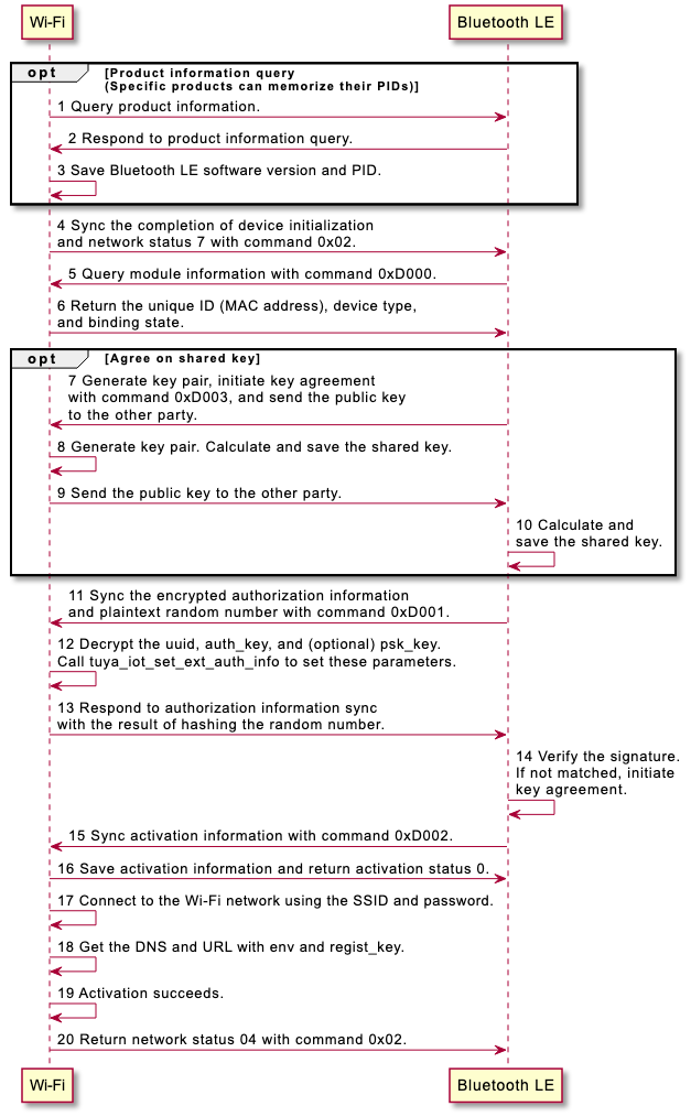
- To use this command, the MCU must set
bit6ofcapto1in the response to the product information query (0x01). - This command is supported by WBRU module only, with the firmware v1.4.0 or later.
Query module information (0xD000)
The MCU sends the following data.
| Field | Bytes | Description |
|---|---|---|
| Header | 2 | 0x55aa |
| Version | 1 | 0x03 |
| Command | 1 | 0xD0 |
| Data length | 2 | 0x0001 |
| Data | 1 | Data[0]: The subcommand 0x00. |
| Checksum | 1 | Start from the header, add up all the bytes, and then divide the sum by 256 to get the remainder. |
The module returns the following data.
| Field | Bytes | Description |
|---|---|---|
| Header | 2 | 0x55aa |
| Version | 1 | 0x00 |
| Command | 1 | 0xD0 |
| Data length | 2 | N |
| Data | N | Data[0]: The subcommand 0x00. Data[1]: The query result.
0: Unbound. 1: Bound. Data[3]: The type of the X module. Only 0x02 and 0x03 are supported currently.
|
| Checksum | 1 | Start from the header, add up all the bytes, and then divide the sum by 256 to get the remainder. |
Sync authorization information (0xD001)
The MCU sends the following data.
| Field | Bytes | Description |
|---|---|---|
| Header | 2 | 0x55aa |
| Version | 1 | 0x03 |
| Command | 1 | 0xD0 |
| Data length | 2 | N |
| Data | N | Data[0]: The subcommand 0x01.Data[1]: The encryption algorithm.
Data[18 to n]: The encrypted authorization information.
{ "uuid":"xxxxxxx", // uuid len 16 bits "auth_key":"xxxxxxx", // auth_key len 32 bits "psk_key":"" // psk_key Reserved } |
| Checksum | 1 | Start from the header, add up all the bytes, and then divide the sum by 256 to get the remainder. |
The module returns the following data.
| Field | Bytes | Description |
|---|---|---|
| Header | 2 | 0x55aa |
| Version | 1 | 0x00 |
| Command | 1 | 0xD0 |
| Data length | 2 | 0x0023 |
| Data | 35 | Data[0]: The subcommand 0x01. Data[1]: The reception result.
|
| Checksum | 1 | Start from the header, add up all the bytes, and then divide the sum by 256 to get the remainder. |
Sync activation information (0xD002)
The MCU sends the following data.
| Field | Bytes | Description |
|---|---|---|
| Header | 2 | 0x55aa |
| Version | 1 | 0x03 |
| Command | 1 | 0xD0 |
| Data length | 2 | N |
| Data | N | Data[0]: The subcommand 0x02. Data[1 to n]: The encrypted activation information.
devId:xxxx, localKey:xxxx, secKey:xxxx, env:xxxx, region:"xxxx, "ssid":"xxxx", "pwd":"xxxx" } |
| Checksum | 1 | Start from the header, add up all the bytes, and then divide the sum by 256 to get the remainder. |
The module returns the following data.
| Field | Bytes | Description |
|---|---|---|
| Header | 2 | 0x55aa |
| Version | 1 | 0x00 |
| Command | 1 | 0xD0 |
| Data length | 2 | 0x0002 |
| Data | 2 | Data[0]: The subcommand 0x02. Data[1]: The reception result.
|
| Checksum | 1 | Start from the header, add up all the bytes, and then divide the sum by 256 to get the remainder. |
Agree on shared key (0xD003)
- Elliptic curve Diffie-Hellman (ECDH) key agreement algorithm is used to create a 32-byte shared key.
- Elliptic curve: secp256r1
- The two parties, each having a public-private key pair, exchange their public values and invoke the shared key algorithm to compute a shared key by combining one’s private key and the other party’s public key.
The MCU sends the following data.
| Field | Bytes | Description |
|---|---|---|
| Header | 2 | 0x55aa |
| Version | 1 | 0x00 |
| Command | 1 | 0xD0 |
| Data length | 2 | 0x0042 |
| Data | 66 | Data[0]: The subcommand 0x03. Data[1]: The elliptic curve.
|
| Checksum | 1 | Start from the header, add up all the bytes, and then divide the sum by 256 to get the remainder. |
The module returns the following data.
| Field | Bytes | Description |
|---|---|---|
| Header | 2 | 0x55aa |
| Version | 1 | 0x00 |
| Command | 1 | 0xD0 |
| Data length | 2 | 0x0042 |
| Data | 66 | Data[0]: The subcommand 0x03. Data[1]: The elliptic curve.
|
| Checksum | 1 | Start from the header, add up all the bytes, and then divide the sum by 256 to get the remainder. |
Proactively synchronize version information (0xD004)
The MCU sends the following data.
| Field | Bytes | Description |
|---|---|---|
| Header | 2 | 0x55aa |
| Version | 1 | 0x00 |
| Command | 1 | 0xD0 |
| Data length | 2 | N |
| Data | N | Data[0]: subcommand 0x04 Data[1-n]: chv information of different channels. You can splice them like this: {"ext_ota":[{"ch":10,"v":"0.1.1"},...{"ch":19,"v":"0.9.1"}]}.
|
| Checksum | 1 | Start from the header, add up all the bytes, and then divide the sum by 256 to get the remainder. |
The module returns the following data.
| Field | Bytes | Description |
|---|---|---|
| Header | 2 | 0x55aa |
| Version | 1 | 0x00 |
| Command | 1 | 0xD0 |
| Data length | 2 | 1 |
| Data | 1 |
|
| Checksum | 1 | Start from the header, add up all the bytes, and then divide the sum by 256 to get the remainder. |
Data forward across lock’s MCU, module, and peephole
- The MCU can query the module information to identify different module solutions.
- Cache and pass through the information from the lock’s MCU, such as battery level and firmware version, to the peephole.
- Cache and pass through the information from the peephole to the lock’s MCU to identify different peephole solutions.
- This command is supported by the WBRU module and camera lock solution.
Lock’s MCU queries module information (0xD100)
The MCU sends the following data.
| Field | Bytes | Description |
|---|---|---|
| Header | 2 | 0x55aa |
| Version | 1 | 0x00 |
| Command | 1 | 0xD1 |
| Data length | 2 | 0x0001 |
| Data | 1 | Data[0]: the subcommand 0x00. |
| Checksum | 1 | Start from the header, add up all the bytes, and then divide the sum by 256 to get the remainder. |
The module returns the following data.
| Field | Bytes | Description |
|---|---|---|
| Header | 2 | 0x55aa |
| Version | 1 | 0x00 |
| Command | 1 | 0xD1 |
| Data length | 2 | N |
| Data | N | Data[0]: The subcommand 0x00. Data[1]: The streaming type.
Format: Length + hardware version string Data[n + 1 to m]: Firmware version, multiple channels allowed. Format: Channel ID + length + firmware version string. |
| Checksum | 1 | Start from the header, add up all the bytes, and then divide the sum by 256 to get the remainder. |
Appendix 1: Event capturing code
| Event type | Code |
|---|---|
| Anti-pry alert | 0x0000 |
| Remote unlocking request | 0x0001 |
| Fingerprint attempt | 0x0002 |
| Password attempt | 0x0003 |
| Card attempt | 0x0004 |
| Face attempt | 0x0005 |
| Palm print attempt | 0x0006 |
| Finger vein attempt | 0x0007 |
| Unlock with fingerprint | 0x0008 |
| Unlock with password | 0x0009 |
| Unlock with card | 0x000A |
| Unlock with face recognition | 0x000B |
| Unlock with palm print | 0x000C |
| Unlock with finger vein | 0x000D |
| Unlock with temporary password | 0x000E |
| Unlock with dynamic password | 0x000F |
| Remote unlocking | 0x0010 |
| Report offline password unlocking | 0x0011 |
| Report doorbell request | 0x0012 |
| Duress alarm | 0x0013 |
| Low battery warning | 0x0014 |
| Mechanical key attempt | 0x0015 |
| High temperature alert | 0x0016 |
| Doorbell ringing and remote unlocking | 0x0017 |
| Loitering alert | 0x0018 |
| Lock tampering | 0x0019 |
| Unlock with special fingerprint | 0x001A |
| Unlocking in arm mode | 0x001B |
Appendix 2: Validity period
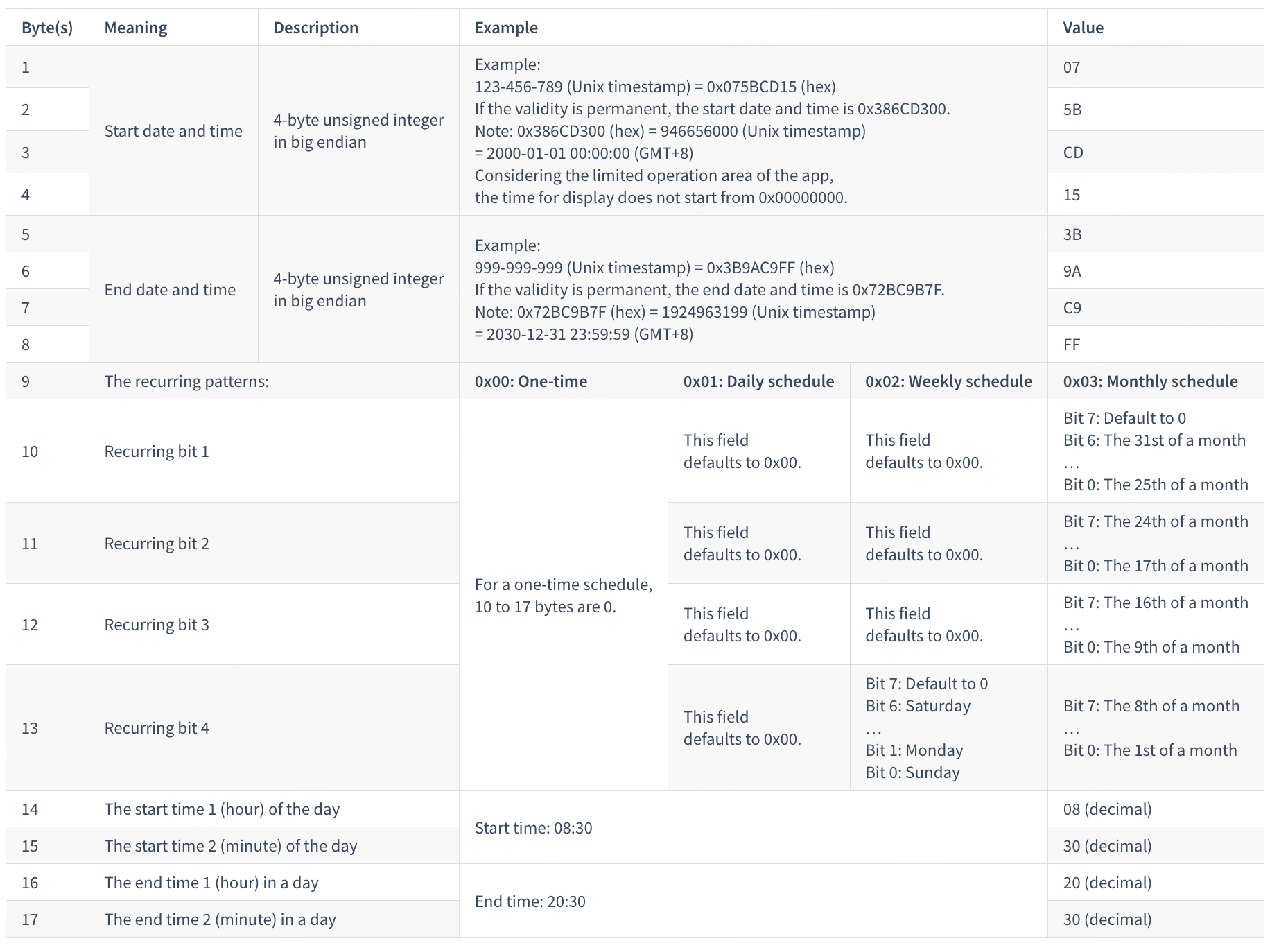
When the user adds or modifies unlocking methods, the recurring validity period and the access times are both applied. There are two use cases:
- When the access times are
0x00, this indicates permanent access. You only need to process the recurring pattern of the validity. - When the recurring pattern is
0x00, this indicates one-time access. You only need to process the access times.
Example: Schedule a password to be valid every Monday to Friday from 08:00 to 08:30 through 2018-01-26 08:00:00 to 2018-08-08 09:56:32. The validity is 5A 6A 6F 80 5B 6A 4D D0 02 00 00 00 3E 08 00 08 1E.
2018-01-26 08:00:00=1516924800(Unix timestamp) =0x5A6A6F80(hex)2018-08-08 09:56:32=1533693392(Unix timestamp) =0x5B6A4DD0(hex)- The recurring pattern:
0x02indicates a weekly schedule. - Recurring bit 1 = Recurring bit 2 = Recurring bit 3 = 0x00
- Recurring bit 4 = 0x3E (Monday to Friday)
- The start time 1 is
0x08. The start time 2 is0x00. - The end time 1 is
0x08. The end time 2 is0x1E.
| Encoding for a weekly schedule | |||||||
|---|---|---|---|---|---|---|---|
| Bit 7 | Bit 6 | Bit 5 | Bit 4 | Bit 3 | Bit 2 | Bit 1 | Bit 0 |
| Reserved | Saturday | Friday | Thursday | Wednesday | Tuesday | Monday | Sunday |
Version history
The following table lists the change history for this document.
| Version | Description | Revision date | Remarks |
|---|---|---|---|
| 2.0.5 | 1. Added extended firmware channels in 0x01 and 0x21.2. Added 0x85 and 0xD004 commands.3. Added WXU type in 0xD100. |
November 26, 2024 | Modified |
| 2.0.4 | 1. In the Data[6] of the 0x1B command, extended the time zone description to support the minute offset.2. In the 0x1D command, optimized the description and MCU usage. 3. In the 0x84 command, retained only the value definition for triggering the module to enter pairing mode. |
March 14, 2024 | Modified |
| 2.0.3 | 1. Added the 0xD3 command to set the sleep parameter. 2. Added the password state 0x02 (deleted) to the response to the 0x1D command. |
October 26, 2023 | Modified |
| 2.0.2 | 1. Added status 10 in reporting network status (0x02). 2. Added the description of using the command 0x84. 3. Added new parameters to the command 0xDA. 4. Added the command 0x6B to get streaming status. |
September 18, 2023 | Modified |
| 2.0.1 | 1. Reviewed and optimized the supported commands for different solutions. 2. Deleted the command 0x66. |
May 26, 2023 | Modified |
| 2.0.0 | Unified the protocols for Wi-Fi lock solutions. | March 8, 2023 | Restructured |
| 1.0.19 | 1. Deprecated some protocols. 2. Moved the description of status data units to appendix 3. 3. Added extended module services and Bluetooth services. |
May 18, 2022 | Modified |
| 1.0.18 | Added four items in Appendix 1. | April 8, 2021 | Modified |
| 1.0.17 | 1. Modified the trigger types in command 0x64 and removed the type of short video. 2. Added the returned status of streaming end in command 0x62. |
March 27, 2021 | Modified |
| 1.0.16 | 1. Added two commands 0x65 and 0x66 for configuring graphics parameters. 2. Removed protocols related to rapid reporting. |
February 26, 2021 | Modified |
| 1.0.15 | Added command 0xF0 for SPI production test. |
February 24, 2021 | Modified |
| 1.0.14 | Added command for short videos and video stream in 0x64 and modified the field of capturing modes. |
January 25, 2021 | Modified |
| 1.0.13 | 1. Added positional notation settings. 2. Added protocols for dynamic passwords and multiple temporary passwords. |
January 6, 2021 | Modified |
| 1.0.12 | Added debugging command 0xDB to define error severities. |
October 14, 2020 | Modified |
| 1.0.11 | 1. Modified logic of uploading images. The MCU triggers image transmission when receiving the network status packet rather than the 0x04 status packet. 2. Modified the correlation logic between the image and the time. Use the module to associate images with events, so the time when an event is reported must be consistent with the one when the MCU transmits an image. |
September 12, 2020 | Modified |
| 1.0.10 | Added protocols to proactively get Wi-Fi status and Unix timestamp. | July 30, 2020 | Modified |
| 1.0.9 | Extended image upload command that applies to module integrated with image capturing. | July 21, 2020 | Modified |
| 1.0.8 | Added data reporting through mobile network operators. | July 13, 2020 | Modified |
| 1.0.7 | 1. Added rapid status reporting. 2. Added pairing mode of EZ and AP coexistence. 3. Added the field of pairing method in product information query. 4. Added functionality of locks with camera. 5. Added the field of capability (cap) to the product information. 6. Added status notification of module reset. 7. Added acquisition of image upload status. |
July 9, 2020 | Modified |
| 1.0.6 | Added periodic temporary password (with schedule list). | October 10, 2019 | Modified |
| 1.0.5 | 1. Added offline dynamic password. 2. Added the report of the MCU serial number. | September 9, 2019 | Modified |
| 1.0.4 | Added low power mode to the network status. | July 13, 2019 | Modified |
| 1.0.3 | Added the command to get DP cache. | July 10, 2019 | Modified |
| 1.0.2 | 1. Added the response parameter when a request for multiple temporary passwords returns no password. 2. Added description of combined unlocking methods. |
December 17, 2018 | Modified |
| 1.0.1 | Added interface for requesting multiple temporary passwords. | October 19, 2018 | Modified |
| 1.0.0 | The first release. | September 15, 2018 | Added |
Is this page helpful?
YesFeedbackIs this page helpful?
YesFeedback


