Wi-Fi Lock Hardware Design
This topic provides hardware design references for non-keep-alive Wi-Fi video door locks. The primary modules used for Wi-Fi door locks include WBRU, WBR1, WBR1-IPEX, and WBR3. This topic focuses specifically on the WBRU and WBR1 modules.
WBRU Wi-Fi module
- Features:
- Built-in low-power KM4 MCU that also acts as an application processor. This module provides an output frequency up to 100 MHz.
- Operating voltage range: 3V to 3.6V.
- Peripherals: 14 GPIO pins, 1 UART pin, and 1 logging port.
- Wi-Fi and Bluetooth connectivity:
- IEEE 802.11b/g/n20 compliant.
- Channels 1-14@2.4GHz (CH1-11 for US/CA, and CH1-13 for EU/CN).
- Support security protocols, including WEP, WPA, WPA2, and WPA2 PSK (AES).
- Support Bluetooth LE 4.2.
- The maximum output power is +20 dBm for IEEE 802.11b transmission.
- Support Wi-Fi Easy Connect (EZ mode), available on Android and iOS devices.
- Onboard PCB antenna or IPEX interface.
- It has passed CE and FCC certifications.
- Operating temperature range: -20°C to +85°C.
- Schematic diagram design:
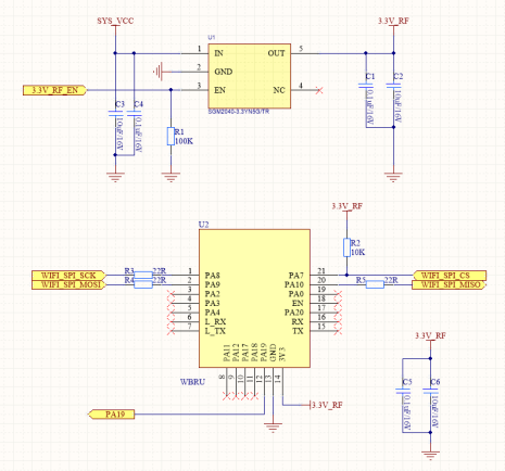
- Considerations: For the WBRU Wi-Fi module interface in door lock applications, the primary connections are power (3V3) and the SPI interface. When designing the door lock circuitry, special attention must be paid to power management for the module. Select a low Iq LDO (such as the SGM2040) or a DC-DC converter. In standby mode, the Wi-Fi power supply must be completely shut down to ensure low power consumption. For video transmission, the module will trigger a falling edge by pulling a GPIO pin (PA19) low to notify the peephole camera MCU to prepare for the next frame transmission. For image transmission, this GPIO pin can be omitted, and SPI commands can be used instead to coordinate the data transfer.
- Pins: For the pin description for the WBRU module, see WBRU Module Datasheet.
Pindicates the power pin, andI/Oindicates the input and output pin.- Pin 18: The enable pin that is active high. The module has pulled up the high level, and users can control this pin externally.
- Pin 19: Pull-up will trigger the testing mode. It is not recommended to add an external pull-up resistor for this pin.
WBR1 Wi-Fi module
-
Features:
- Built-in low-power KM4 MCU that also acts as an application processor. This module provides an output frequency up to 100 MHz.
- Operating voltage range: 3V to 3.6V.
- Peripherals: 7 GPIO pins and 2 UART pins.
- Wi-Fi and Bluetooth connectivity:
- IEEE 802.11b/g/n20 compliant.
- Channels 1-14@2.4GHz (CH1-11 for US/CA, and CH1-13 for EU/CN).
- Support Bluetooth LE 4.2.
- Support security protocols, including WEP, WPA, WPA2, and WPA2 PSK (AES).
- The maximum output power is +20 dBm for IEEE 802.11b transmission.
- Support Wi-Fi Easy Connect (EZ mode) pairing mode on Android and iOS devices.
- Onboard PCB antenna.
- It has passed CE and FCC certifications.
- Operating temperature range: -20°C to +85°C.
-
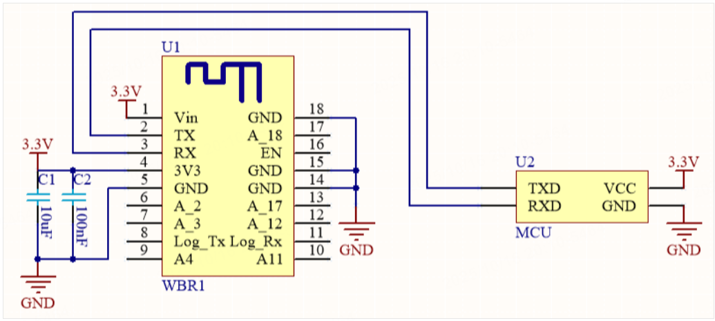
Schematic diagram design:
-
Considerations: For the WBR1 Wi-Fi module interface in door lock applications, the primary connections are power (3V3) and the UART (user serial port). When designing the door lock circuitry, special attention must be paid to power management for the module. Select a low Iq LDO (such as the SGM2040) or a DC-DC converter. In standby mode, the Wi-Fi power supply must be completely shut down to ensure low power consumption.
-
Pins: For the pin description for the WBR1 module, see WBR1 Module Datasheet.
Pindicates the power pin,I/Oindicates the input and output pin, andAIindicates the analog input signal.RSTis only a module hardware reset pin and cannot clear Wi-Fi pairing information.- Pin 17 (TOUT): This pin can only be used as an ADC port and must not be configured as a GPIO pin. When not in use, it should be left floating. When functioning as an ADC input, its voltage range is 0V to 1.0V.
- UART0: This is the user serial port. The module outputs information via this UART during power-on initialization. Users can safely ignore this boot-up output.
Wi-Fi antenna design
The Wi-Fi modules provided by Tuya apply to door locks. However, the metal structure of door locks might have an impact on the RF performance of antennas. Therefore, in the early layout design, the position and overall structure of the antenna must be optimized to minimize its impact on RF performance.
Onboard PCB antenna and IPEX external antenna are available.
Considerations for onboard PCB antenna
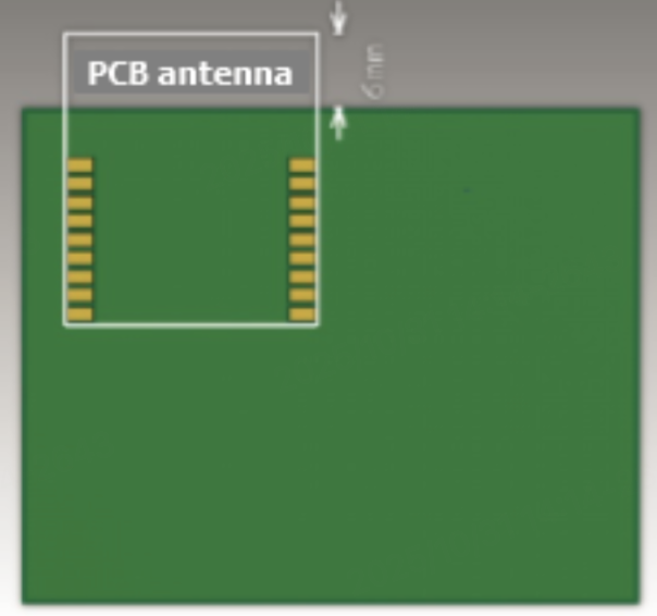
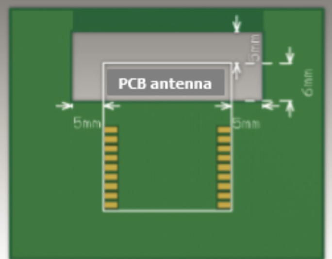
If the mechanical design permits, ensure the onboard antenna is positioned against the door lock’s non-metallic casing. For SMT modules, adhere to the PCB layout reference shown in the figure below as closely as possible.
Make sure that a substrate medium does not exist below the antenna. A copper pour area is not found around the antenna to minimize the impact on the antenna performance. If located too close to the antenna, copper foil might affect the resonance point of the antenna, or the substrate medium might reduce the radiation efficiency of the antenna.
- The antenna is located inside the backplane frame.
- The antenna is located along the backplane frame. No copper pour area is allowed inside the frame.
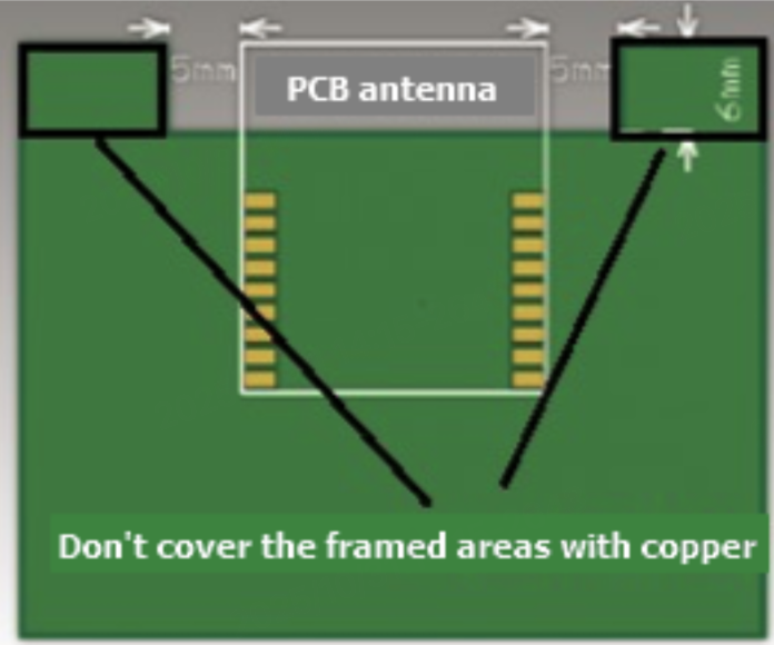
- The antenna is located along the midline of the backplane. The backplane frames around the antenna are hollowed out.
The core principle for all the above configurations is to ensure:
-
There is no substrate medium or metal structural components from the door lock directly above or below the printed antenna.
-
The printed antenna is positioned away from metal copper foil to maximize radiative performance.
A PCB antenna provides limited performance for a module. We recommend that you use an external antenna if conditions permit.
Considerations for external IPEX antennas
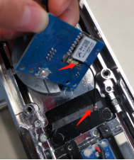
An IPEX external antenna is an ideal option for a Wi-Fi module that is used by a smart door lock. Put the antenna at the optimal position away from the interference of metal parts. For example, the antenna can be installed in the battery box inside the door, on the touch acrylic panel outside the door, or at the reset button inside the door.
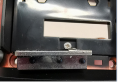
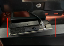
To fix a flexible printed circuit (FPC) antenna, you can choose to stick the antenna on a non-metal shell or use an antenna bracket. For more information, see the following examples.
- Stick the antenna on a non-metal shell
- Use an antenna bracket
Is this page helpful?
YesFeedbackIs this page helpful?
YesFeedback


