Wi-Fi Lock Implementation Process
This topic applies to MCU integration solutions for Wi-Fi locks, and describes data point (DP) settings and relevant data transmission. It fits the hardware development phase.
| Version | Description | Date | Remark |
|---|---|---|---|
| V1.0.1 | Modification | August 13, 2020 | Content updates |
Data transmission process
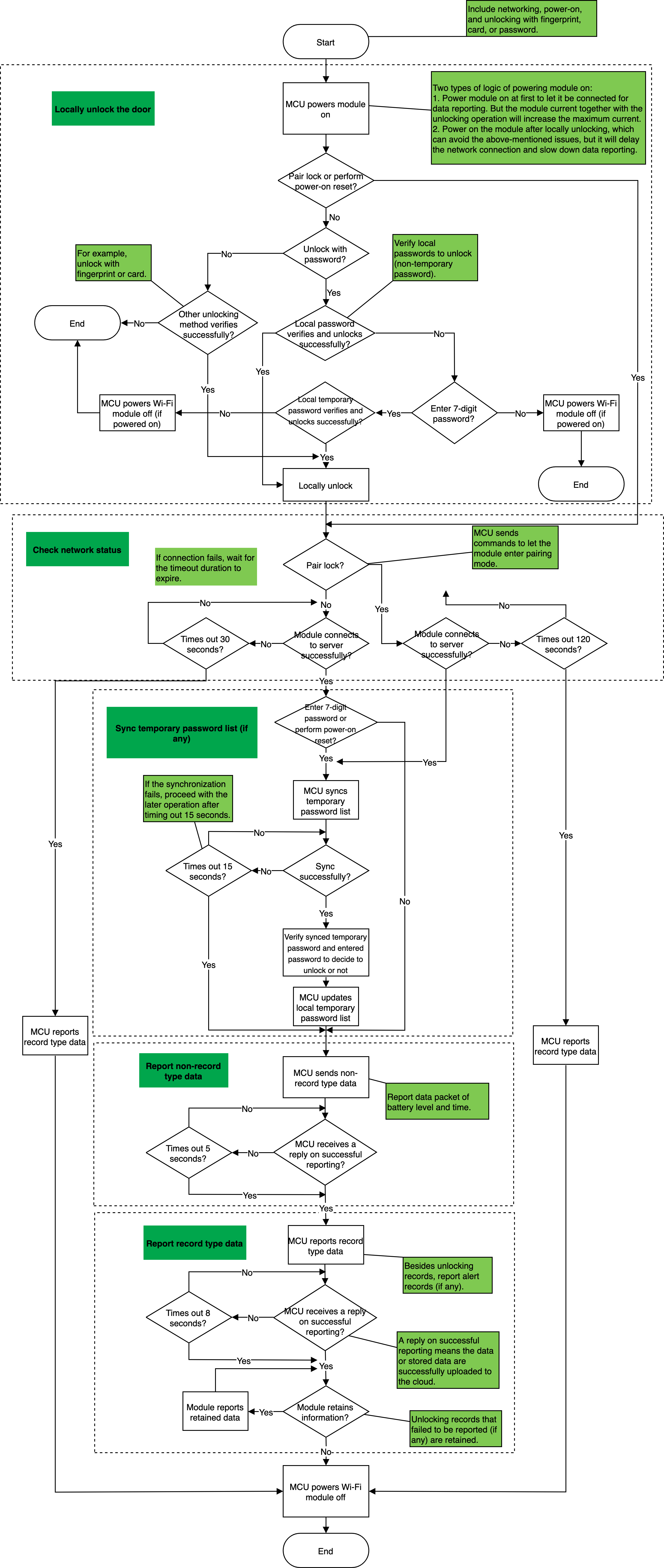
The data transmission process of Wi-Fi locks is as follows:
- Unlock by local verification.
- Determine network status of the module.
- Synchronize the temporary password list and verify to unlock. This step is necessary if temporary password unlocking is available.
- Report non-record type data, including time and battery level.
- Report record type data, including unlocking and alert record.
Note: Read the flowchart carefully before proceeding with development.
Pairing
Scenario
For first-time pairing or pairing again after removing the network, you do not need to manually set the DPs. The data transmission is as follows.
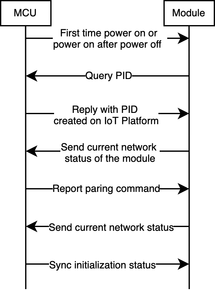
After successful pairing, power the module on to transmit data and wait for the server connection result returned from the module. Two pairing modes are available for Wi-Fi locks.
- EZ mode (SmartConfig): Pair devices via a router.
- AP mode: Pair devices via a hotspot.
For more information about these two pairing modes, see User Manual (V3.21.0).
Relevant MCU commands: Query product information. Report networking status. Reset Wi-Fi or reset Wi-Fi and select pairing mode.
Battery level display
Scenario
Display device’s current battery level.
Relevant DPs
- Display battery level as high, medium, and low.
- Display remaining battery level percentage.
Note: Choose one from the two DPs as needed, both of which indicate the current battery level.
DP description
-
Battery level: Display remaining battery level as high, medium, and low.
-
Remaining battery level: Display remaining battery level percentage, ranging from 0 to 100.
Report the battery level under the following scenarios:
- First-time pairing or pairing again.
- Device reboot, such as after replacing the battery.
- The battery level is changed.
- Regular reporting, such as reporting once every 10 days.
Relevant MCU commands: Report real-time status.
Unlocking record
Scenario
View the unlocking record on the app.
Relevant DPs
- Fingerprint number
- Card number
- Face number
- Password number
- Temporary number
- Dynamic password number
- Key number
- Remote unlocking
- Unlocking from the inside
Note: Contact the project manager to grant permission to display unlocking record on the app with no limit on the number of records.
DP description
- Fingerprint number, card number, face number, and password number: The DP values are used to distinguish members, ranging from 0 to 999. The unlocking record is displayed on the app, with corresponded member information. For example, if the DP value of the reported fingerprint number is 25, Fingerprint 25 unlocks will be displayed on the app.
- The key number, temporary password number, dynamic password number, and unlocking from the inside: The DP values do not have a special meaning, ranging from 0 to 999. The unlocking record is displayed on the app, without corresponding member information. For example, if the DP value of the reported key number is 25, Key unlocks will be displayed on the app.
Implementation process
Implementation logic
When the door is opened, the DP of the corresponding unlocking method is reported. In the case of network disconnection, the unlocking record data must be still consistent with the actual event. Therefore, it is recommended to report the data by record type. The module saves the data that failed to be reported, which will be reported again. The record type data carries the local time of the device. For more information about DP values, see the following table.
| Unlocking method | Reported DP | DP value |
|---|---|---|
| Fingerprint unlocking | Fingerprint number | Correspond to the actual DP value. |
| Password unlocking | Password number | Correspond to the actual DP value. |
| Temporary password unlocking | Temporary number | It can be any values. |
| Dynamic password unlocking | Dynamic password number | It can be any values. |
| Card unlocking | Card number | Correspond to the actual DP value. |
| Face recognition unlocking | Face number | Correspond to the actual DP value. |
| Key unlocking | Key number | It can be any values. |
| Remote unlocking with an app | Remote unlocking | It can be any values. |
| Unlocking from the inside | Unlock from the inside | It can be any values. |
Implementation process
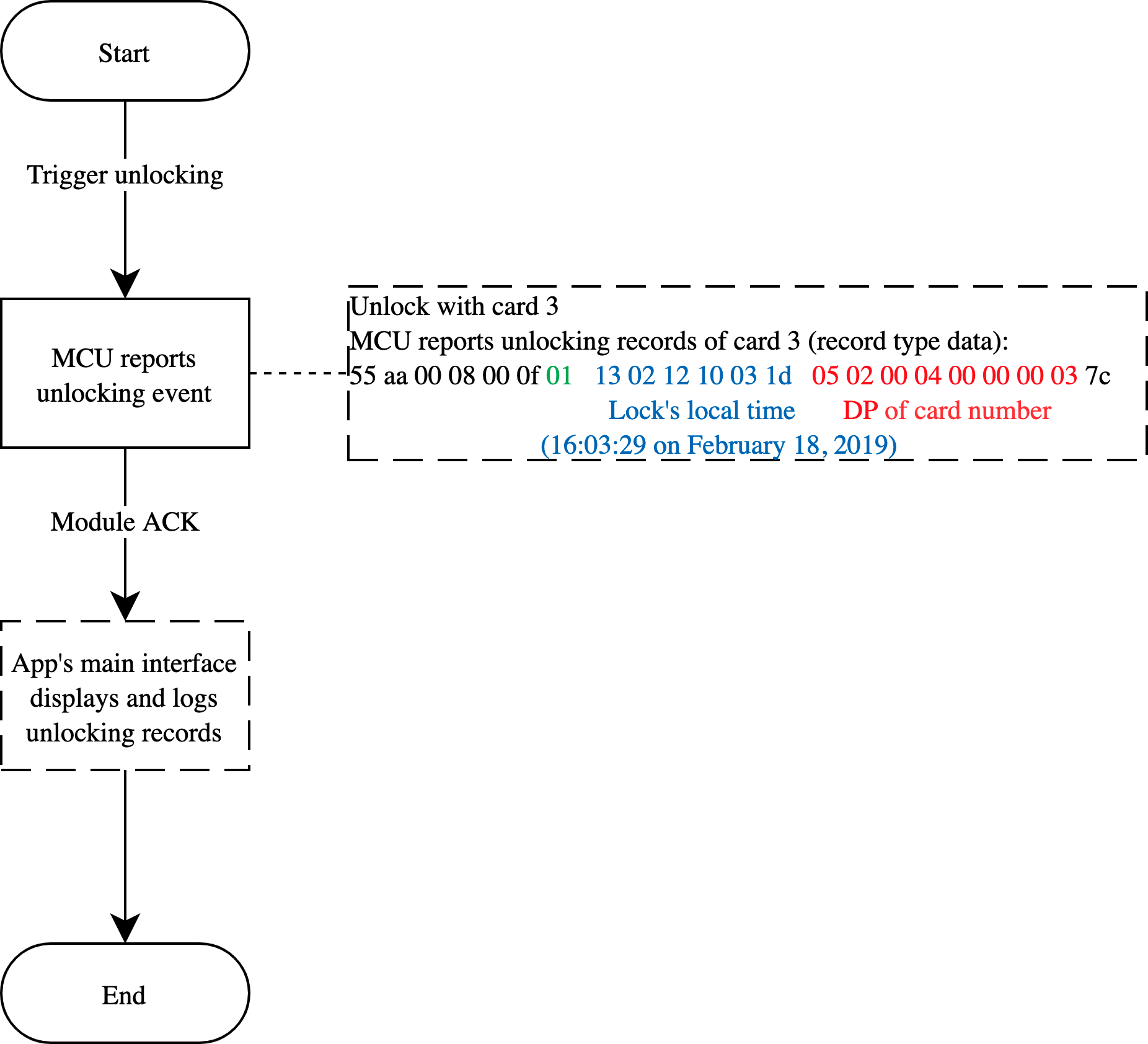
Relevant MCU commands: Report the record type data
Note: The relevant numbers are generated by the MCU, especially the temporary password number. The MCU number is independent of the temporary password number.
Member management
Scenario
Add members and bind the fingerprint number, password number, card number, and face number. The app will convert the reported number to the corresponding member name for display. For example, add a member as daughter and bind it to card 3. When the device reports the unlocking record of card 3, the app will display Daughter, card unlocking. Note that if no member is bound, the app will display Card 3 unlocking.
Implementation process
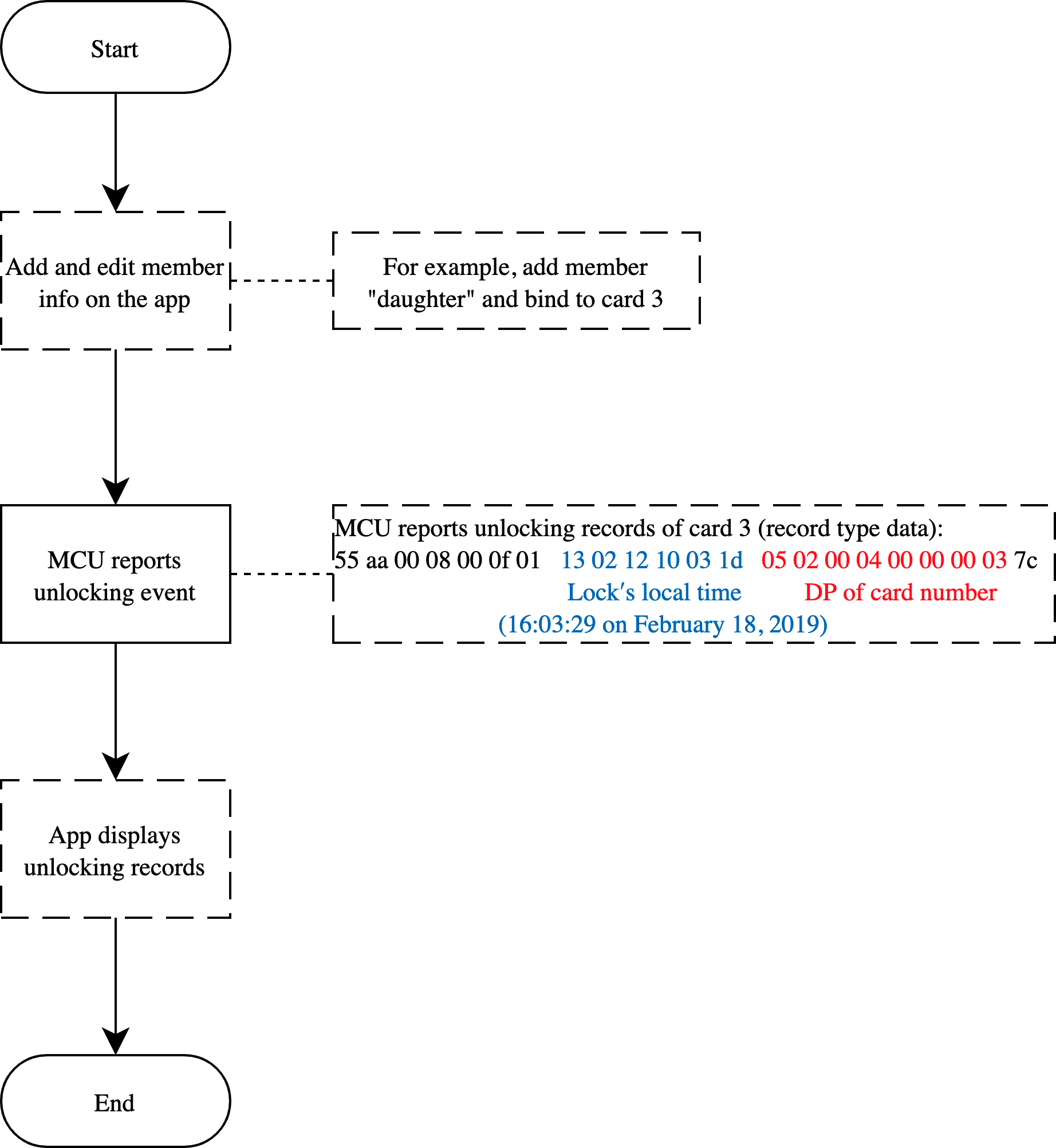
Relevant MCU commands: It is the app functionality and no communication protocols are involved.
Alerts
Scenario
When an alert is triggered, it will be instantly sent to the app. Alert record is also available on the app.
Relevant DPs
- Alert
- Duress alert
- Doorbell calling
Note: Contact the project manager to grant permission to display unlocking record on the app with no limit on the number of records.
DP description
-
Alert: The alerts cover multiple scenarios, including fingerprint attempt, password attempt, card attempt, face recognition attempt, bolt stuck, high temperature, overtime unclosed reminder, electronic lock tongue not extending, anti-pry, key insertion, low battery, out of battery, and vibration alert.
-
Duress alert: Select this DP if the duress alert is available. Since this functionality is implemented in the cloud, not by the device, you can ignore the DP value. For example, if the user sets the fingerprint 3 for duress alert, an alert will be triggered when the server receives an unlocking operation with fingerprint 3.
-
Doorbell calling: If the lock has a doorbell, the DP value is
0or1. The doorbell alert record will be displayed on the app.
Implementation process
Implementation logic
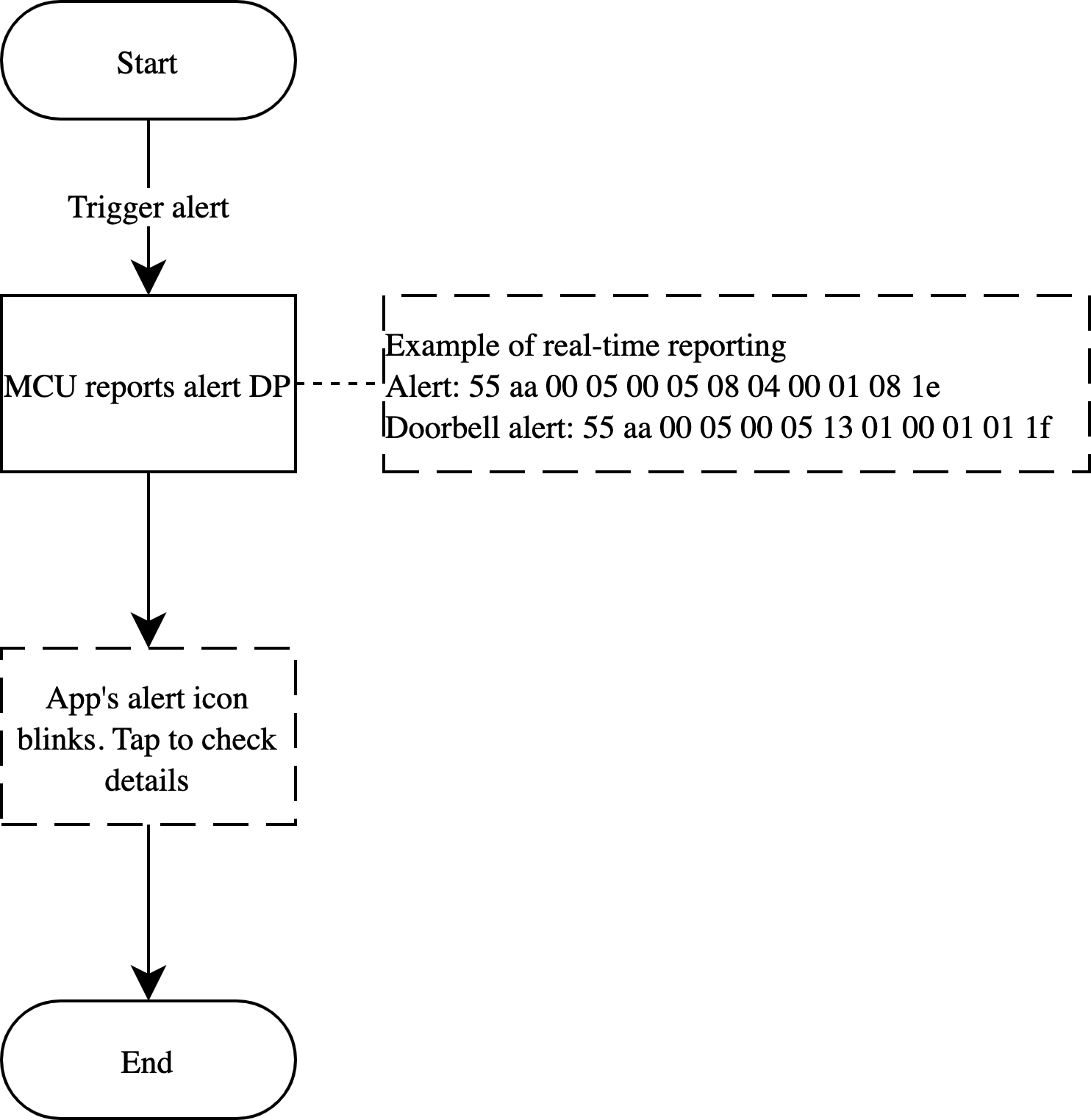
When an alert is triggered, the MCU reports corresponding alert DP value.
Note: If reporting the data by record type, use the device time and respect the time accuracy. If the device time lags behind the actual time, the app’s alert icon does not blink on receiving this alert, and users need to tap the icon to view it. If the server time prevails, when the device reconnects after a network failure, the recorded time is not consistent with the actual event time.
Door and doorbell alerts
Duress alert
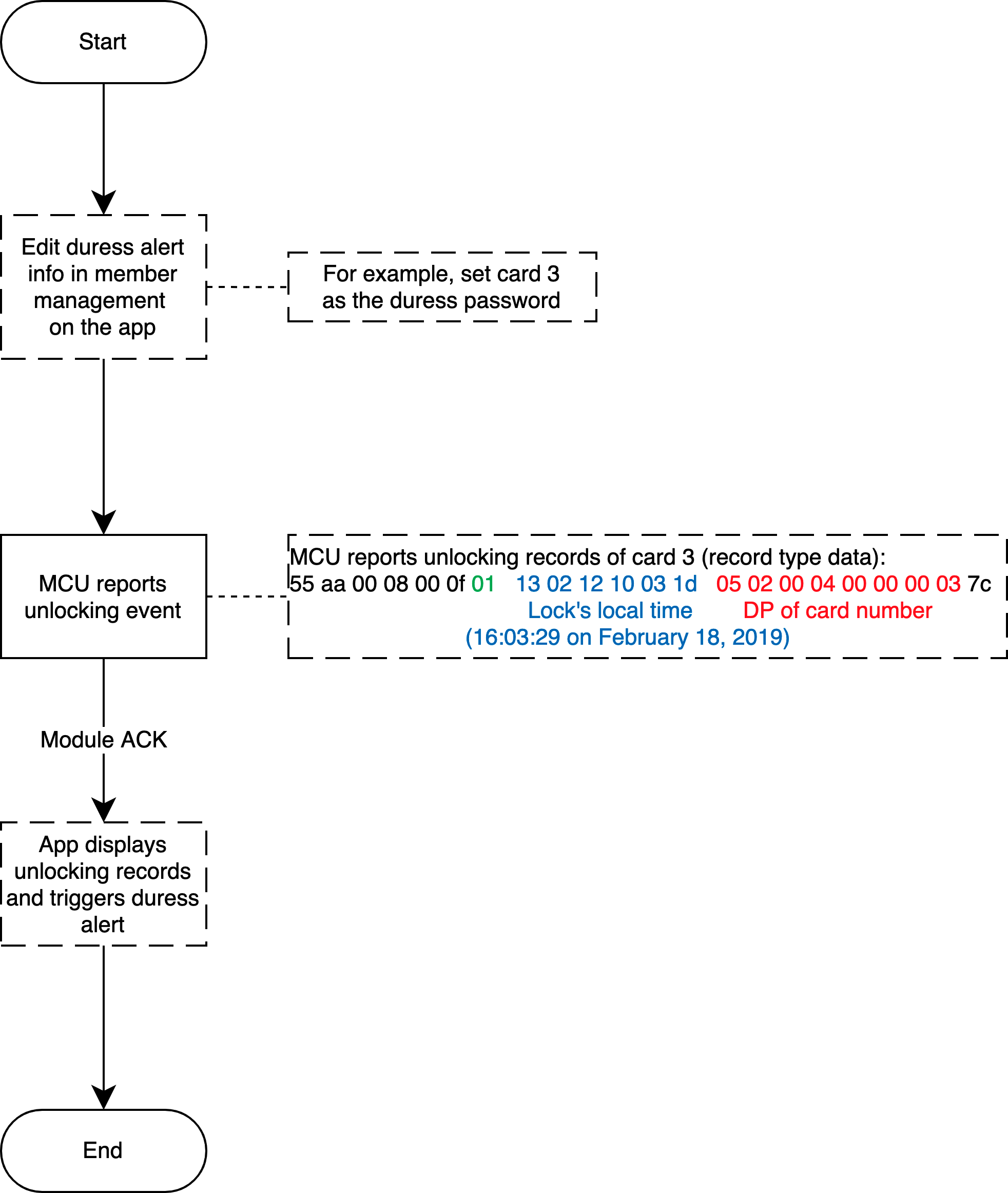
Relevant MCU commands: Report the record type data
Remote unlocking
Scenario
The visitor enters a specific unlocking code to trigger remote unlocking, and the owner can respond to the unlocking request during a limited time period. Manufacturers decide the trigger method, for example, pressing a specific physical button or entering a specific unlock code, such as 888#.
Relevant DPs
- DP 9: Count down a remote unlocking request.
- DP 15: Unlock the door on the app.
- DP 49: Set a key to remote unlocking.
- DP 50: New password-free remote unlocking, with a key.
DP description
-
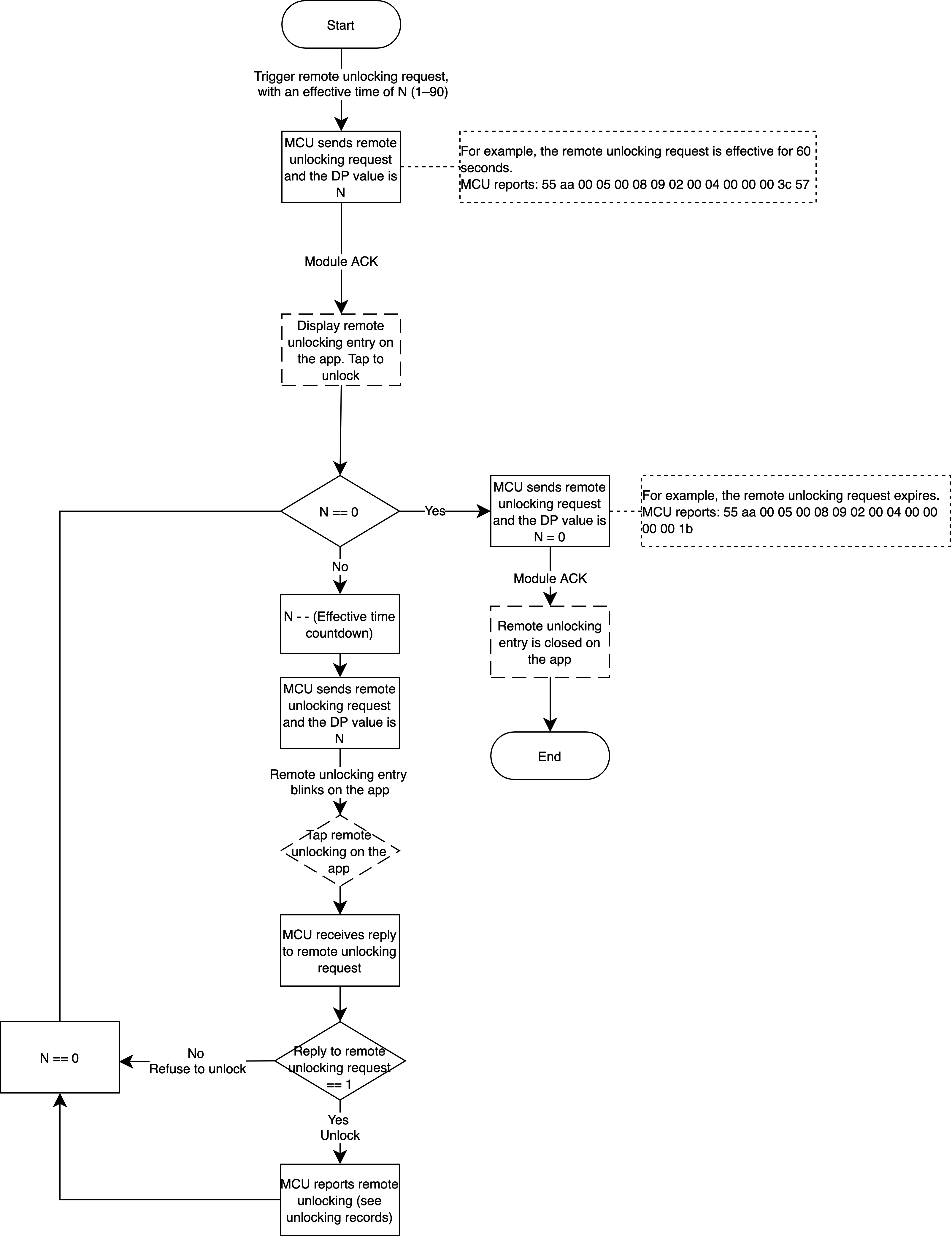
Remote unlocking request: The lock proactively reports remote unlocking requests. The DP value indicates the remaining time for remote unlocking, ranging from 0 to 90. The remote unlocking entry will be enabled on value
1to90and closed on value0. When the request is triggered, the device reports the DP with the valid remaining time (non0), the app panel enables the unlocking entry. Then the device starts to count down the valid remaining time and reports it. The unlocking entry blinks until the valid remaining time reaches0when the unlocking entry is closed. -
The countdown of the valid time is reported in reverse order by the MCU. For example, the valid time is reported as
90,89,88,87. It can be reported once in 1s or in 2s after the app responds. When the valid time counts down to0, or the app sends a command to unlock or refuse to unlock the door, the MCU must report0after receiving the command. Otherwise, the door status in the cloud cannot be reset.
Implementation process
Implementation logic
The device initiates a remote unlocking request, and users respond to it on the app. The lock is controlled as per the command from the app and meanwhile reports a request to close the unlocking request. When the request times out, that is, the valid remaining time counts down to 0, the lock reports a request to close the unlocking request.
Implementation process
Relevant MCU commands: Instantly report the status. The module sends the command.
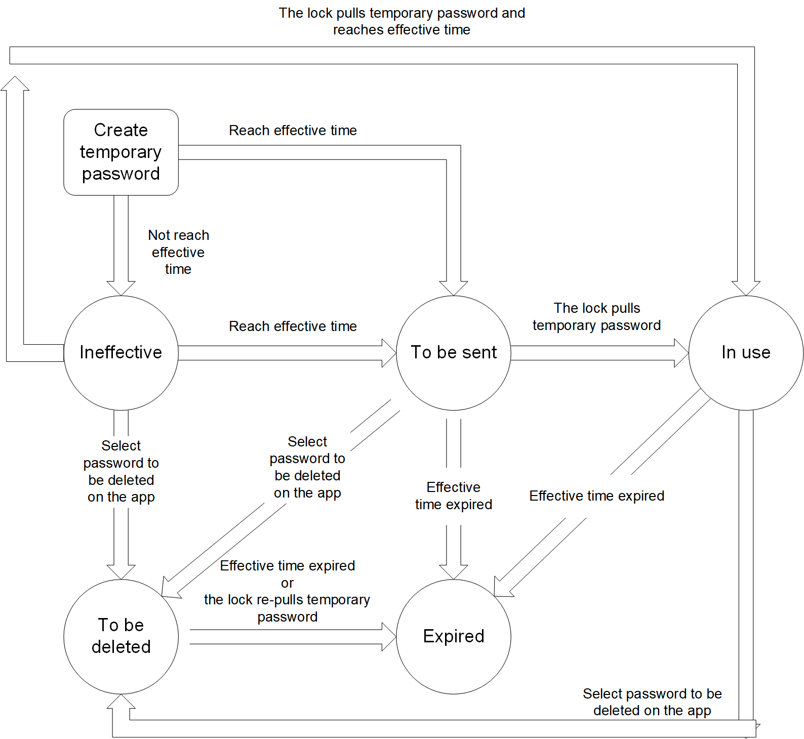
Temporary password
Scenario
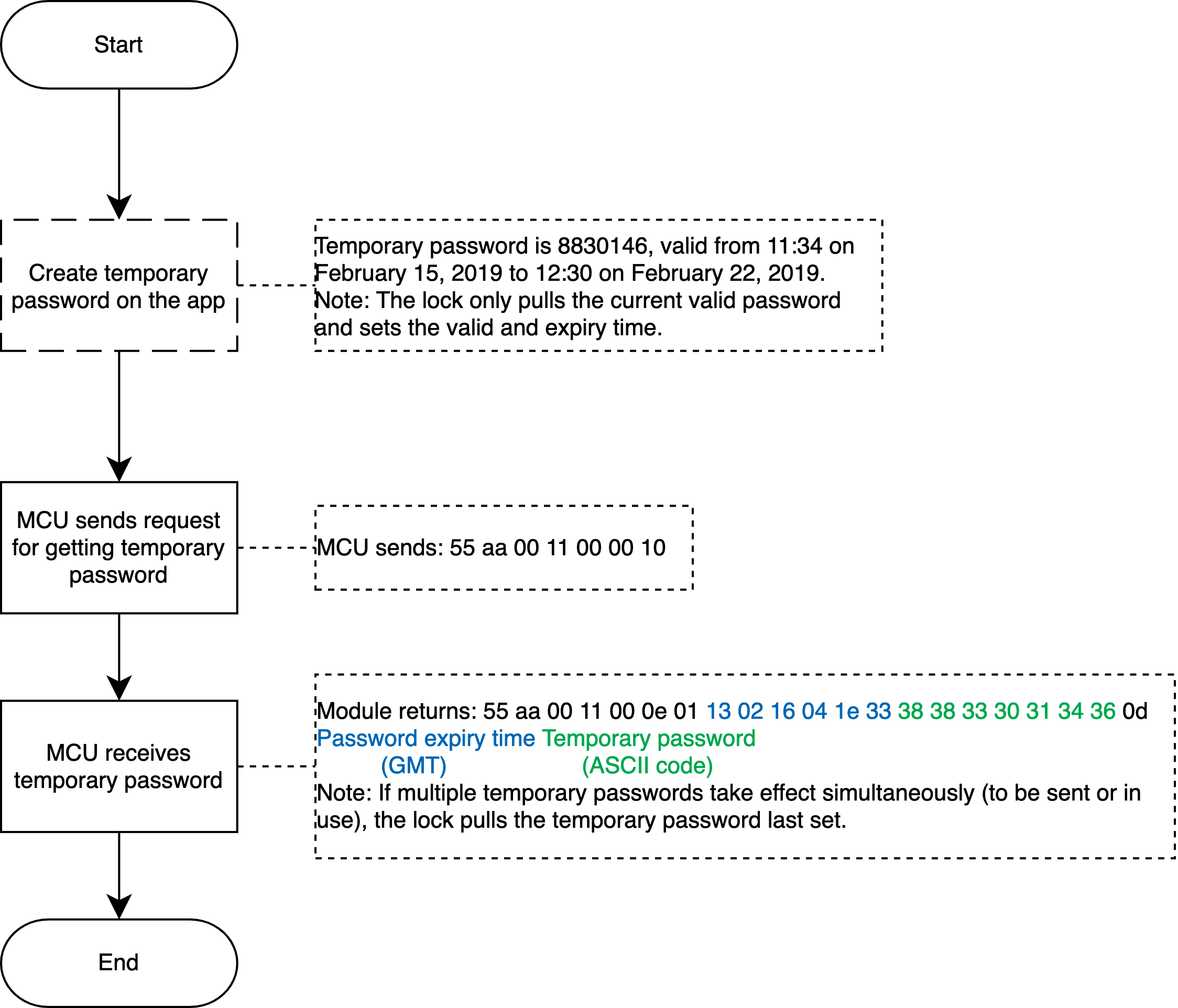
The user sets a temporary password on the app, which can be used by a visitor to unlock the door within the valid time. To implement this functionality, the lock must be equipped with a clock chip. It is recommended that the temporary password be obtained and saved locally.
Temporary password status
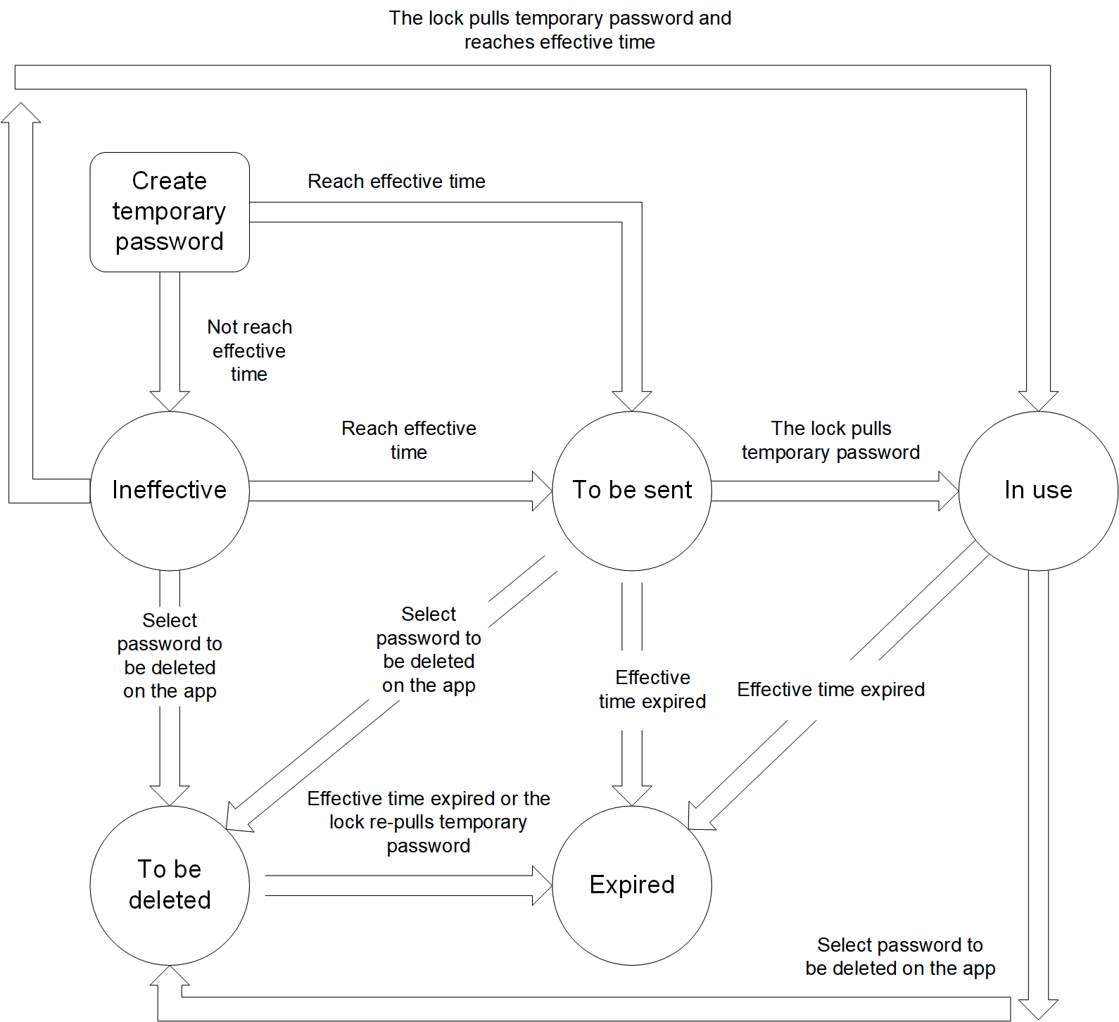
- Not take effect: The password has not taken effect.
- To be sent: The password takes effect but is not sent to the lock.
- In use: The password takes effect and is sent to the lock.
- To be deleted: The password is deleted on the app, but the command has not been sent to the lock. The lock has not applied for a temporary password again.
- Expired: The valid time expired, or the password is deleted on the app and the command has been sent to the lock.
The data transmission is as follows.
Implementation process
Development process
See the following figure. When the MCU proactively synchronizes the temporary password list with the server, the synchronization might be failed due to network failure or other problems. In this case, the password list will remain unchanged.
Get multiple temporary passwords
The full temporary password is sent by the server each time. Therefore, the lock shall update the local list as per all the data returned by the server.
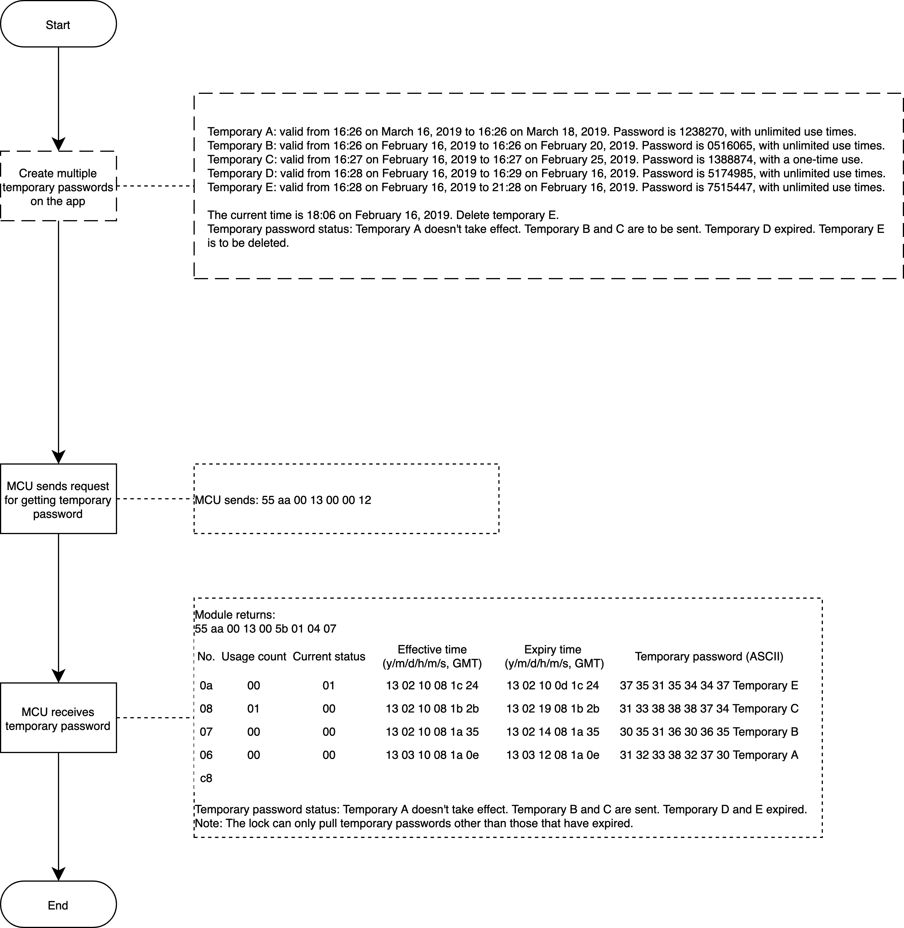
Relevant MCU commands: Request temporary passwords in the cloud (support multiple passwords).
Dynamic password
Scenario
The user generates a dynamic password on the app, which can be used by a visitor to unlock the door within the valid time.
Implementation process
Implementation logic
Get a dynamic password on the app. When it is used to unlock the door, the lock will report this event. The module returns the verification result that controls the unlocking operation. Note that the timestamp in the command of reporting the dynamic password must be the Greenwich Mean Time (GMT) instead of local time. The dynamic password is valid within five minutes and shall be obtained again after timeout.
The dynamic password is a kind of temporary password that can be generated without network access. This functionality is implemented by algorithms. When the app requests a current dynamic password from the server, if the lock receives a password that is suspected to be a dynamic password, the lock submits the password to the module, along with the current time and administrator password. When the module receives these data, on the basis of the saved initial key, it will operate a password that will be compared with the password entered by the user. If these two passwords match, the module will tell MCU to unlock the door. Otherwise, the door is not unlocked.
Note: Get the dynamic password on the app. Currently, the all-in-one Wi-Fi panels do not support entering an administrator password, but it is supported on the embedded system and server.
Implementation process
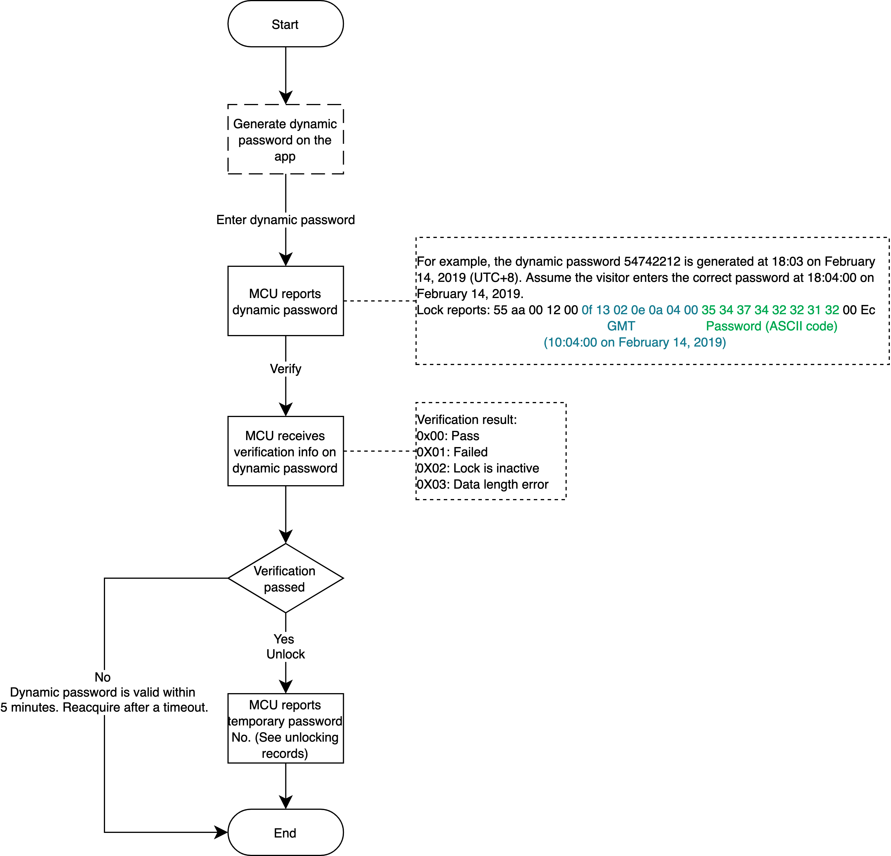
Relevant MCU commands: Dynamic password verification
Text message notification of temporary password
Scenario
This functionality corresponds to the temporary password. When the user creates a temporary password on the Tuya app or OEM app, a text message can be sent to a specified phone number. The text message contains the device name, seven-digit password, effective time, and expiry time.
When creating a temporary password on the app, the user can select the country/region code.
Relevant DPs
- Text message notification
DP description
This DP is optional. This functionality is a paid offer.
After selecting the DP, you need to subscribe to this functionality from the value-added services on the Developer Platform.
Operation process: Go to Tuya Value Added Service, click Functional Expansion, find Door Lock SMS Notification, and subscribe.
It is the app functionality and no communication protocols are involved.
Synchronize unlocking methods
Scenario
When the local unlocking method is changed, added, or deleted, all the local unlocking IDs will be synchronized with the cloud.
Relevant DPs
- Synchronize all finger vein numbers
- Synchronize all palm print numbers
- Synchronize all iris numbers
- Synchronize all face numbers
- Synchronize all card numbers
- Synchronize all password numbers
- Synchronize all fingerprint numbers
DP description
Divide the unlocking method into 125 copies, and each with eight copies corresponds to a byte of eight bits. Then, exactly 1,000 passwords can be saved, and meet the maximum length of 255 bytes for DP reporting.
byte[0] indicates sharding position. byte[1] indicates the unlocking method on this sharing. If the bit corresponding to the label bit on the unlocking method byte data is 1, indicating that the password exists.
For example, 00000001 00010011 indicates that the unlocking methods 0, 1, and 4 exist on the first sharding.
01000001 00100101 indicates the position 0, 2, and 5 on the 65th sharding (2^6 + 1). The actual password number on position 5 is 64 x 8 + 5 = 517.
00000010 00000000 indicates empty sharding that needs to be processed by the hardware. To reduce the actual length, there is no need to upload it.
Note: Sharding starts from
1, rather than0. For example, the eighth password should belong to the second sharding, and a sharding has only eight passwords, corresponding to values0to7.
Implementation process
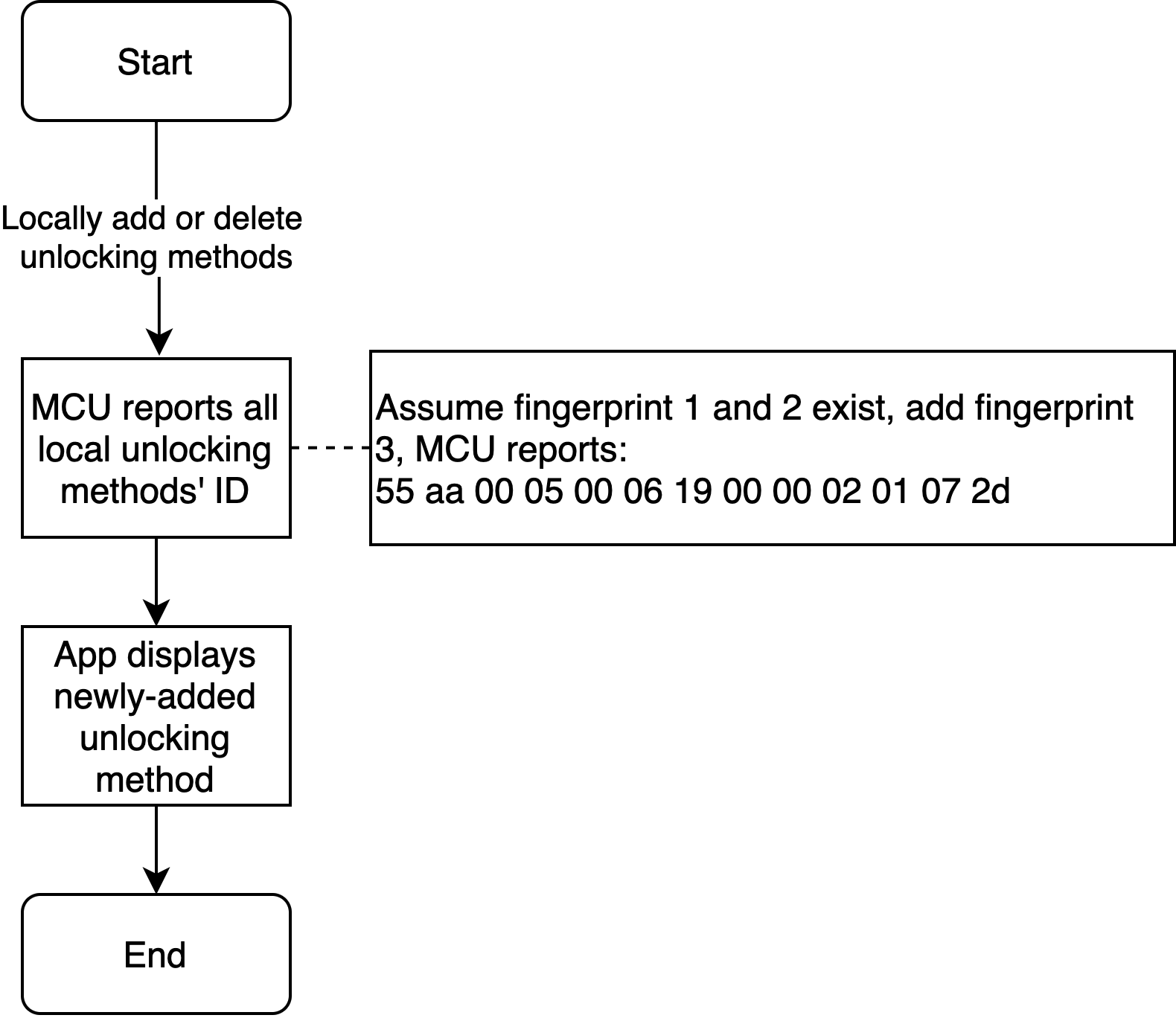
Note: All the local IDs after updates shall be synchronized with the cloud every time.
Relevant MCU commands: Report real-time status.
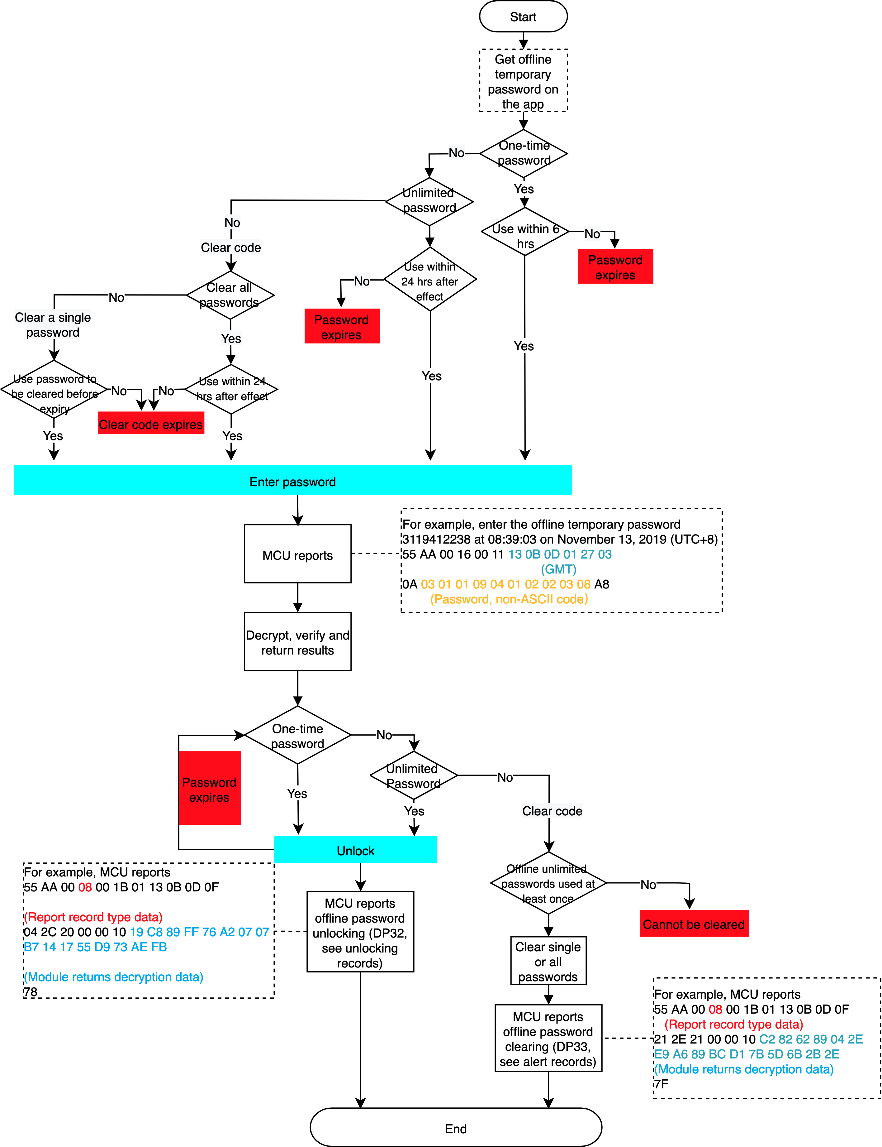
Offline temporary password (Pro version only)
Scenario
Use offline temporary passwords when Wi-Fi is disconnected or Wi-Fi signal is poor, that is, when the door lock disconnects from the network.
Usage description
One-time password
It can be used once within six hours after generation and expires after use. Within 60 minutes on the hour, there are only 10 one-time passwords available.
Password of unlimited usage times
It can be used multiple times within the effective period and the longest period can be one year. Within 24 hours after the password takes effect, it must be used once. Otherwise, it will automatically expire. One lock can only get the password once within the same expiry time period.
Clear all passwords
The user can only clear all offline unlimited passwords that have been used at least once. They cannot clear one-time passwords and unlimited passwords that have never been used. After generating a clear code, it must be used within 24 hours. Within 60 minutes on the hour, there are only 10 clear codes available.
Clear a single password
The user can only clear single offline unlimited passwords that have been used at least once. They cannot clear one-time passwords and unlimited passwords that have never been used. After generating, the clear code has the same expiry time as the password to be cleared.
Implementation process
Implementation logic
Get an offline temporary password on the app. When it is used to unlock the door, the lock will report this event. The module returns the verification result that controls the unlocking operation. Note that the timestamp in the command of reporting the offline temporary password must be the Greenwich Mean Time (GMT) instead of local time.
Implementation process
Online cycle password (Pro version only)
Scenario
The user sets an online cycle password on the app, which can be used by a visitor to unlock the door within a scheduled time period.
Online cycle password status
-
Not take effect: The password has not taken effect.
-
To be sent: The password takes effect but is not sent to the lock.
-
In use: The password takes effect and is sent to the lock.
-
To be deleted: The password is deleted on the app, but the command has not been sent to the lock. The lock has not applied for a temporary password again.
-
Expired: The valid time expired, or the password is deleted on the app and the command has been sent to the lock.
The data transmission is as follows.
Implementation process
Implementation logic
Create an online password on the app, set effective and expiry time, and choose whether to schedule it. To differentiate from other password types, the online cycle password uses 7-digit valid data. When the lock’s master board detects that a user unlocks with multiple temporary passwords, it shall call corresponding APIs to get relevant data. Full passwords are sent each time, and the lock shall update the local list as per all the data returned by the server.
Implementation process
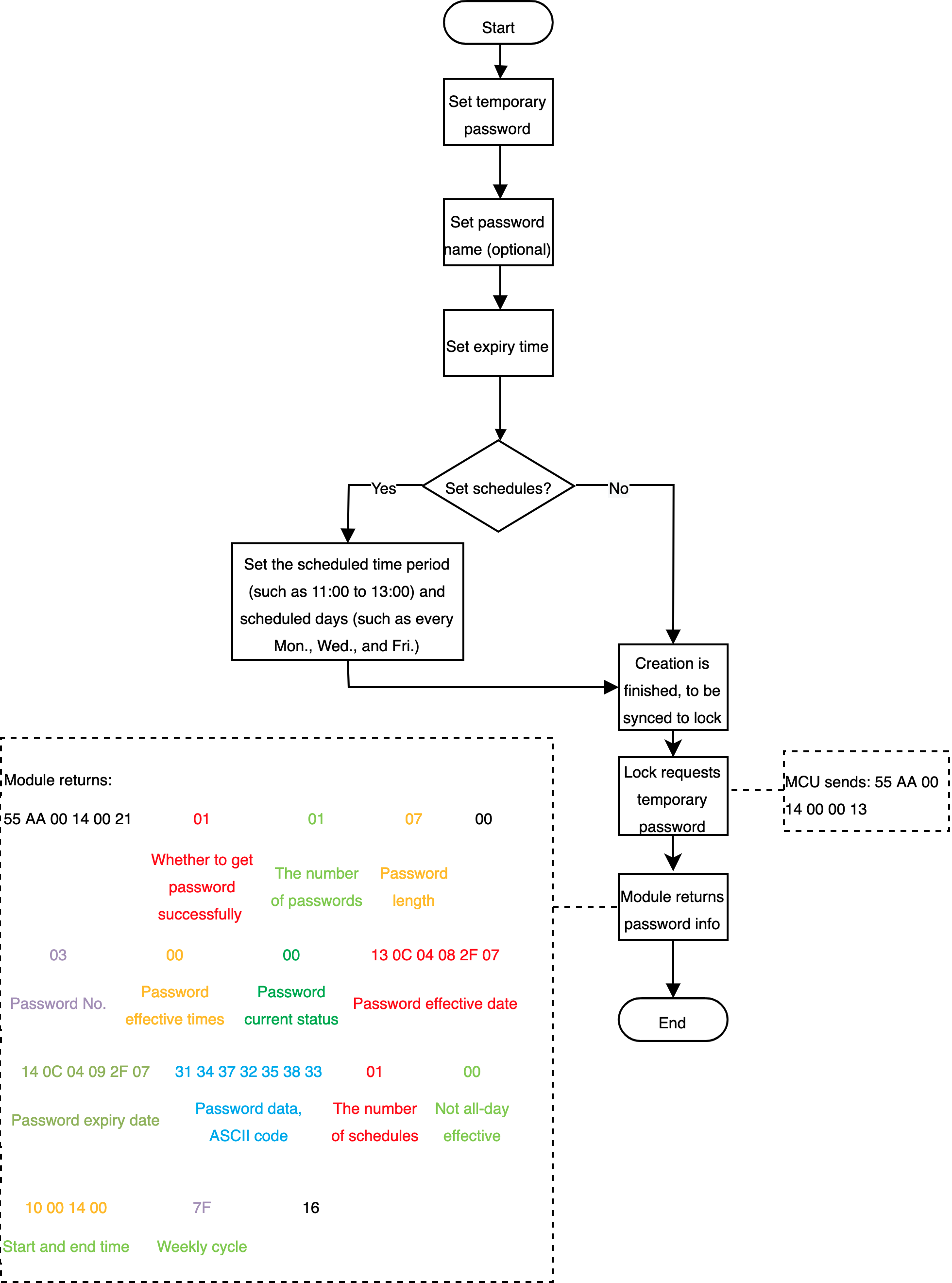
Relevant MCU commands: Request a temporary password from the cloud (with schedule list).
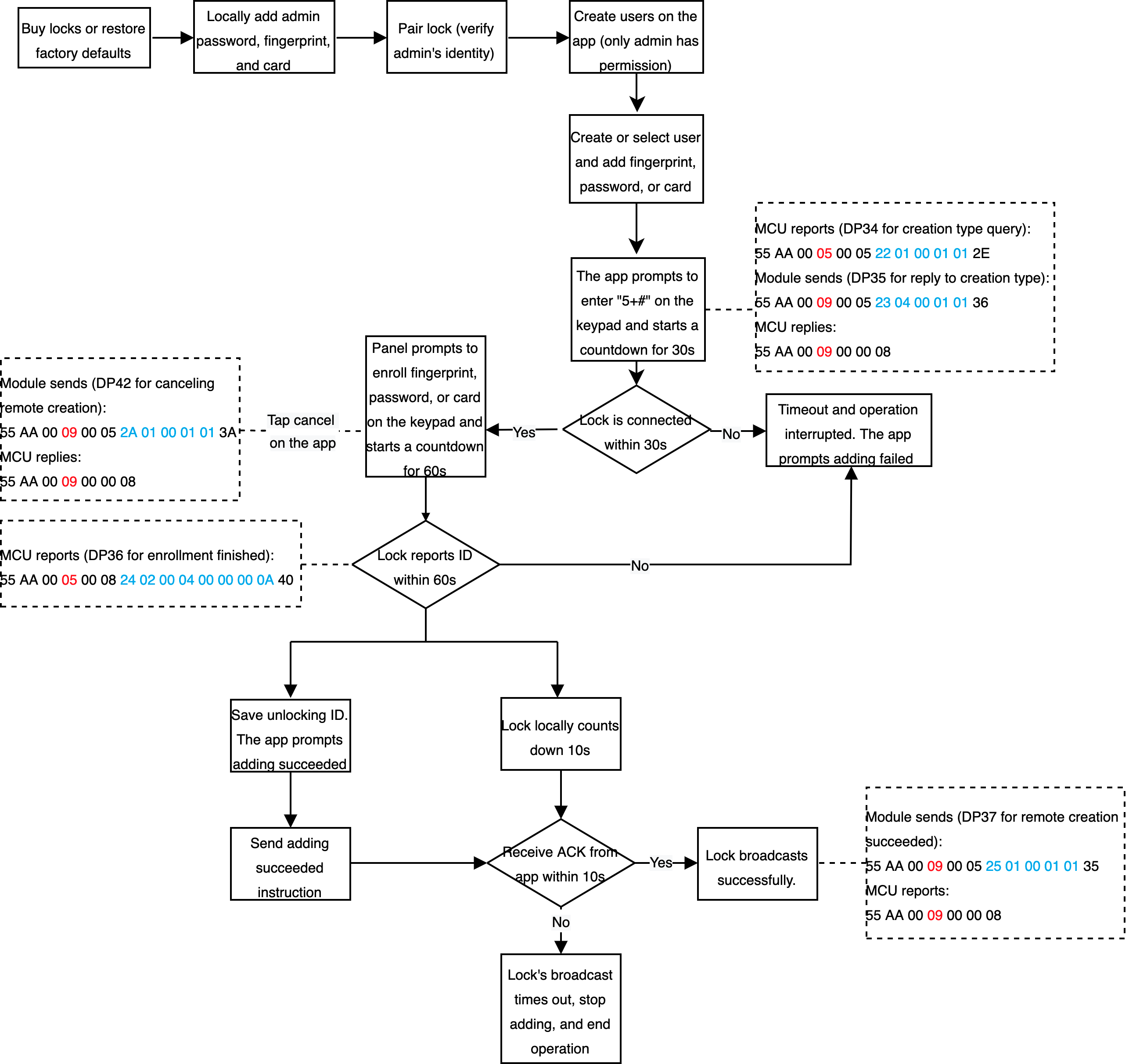
Enroll unlocking methods on the app (Pro version only)
Scenario
Add unlocking methods through the app, such as fingerprint, door card, and password.
Relevant DPs
- Query creation type
- Reply to creation type
- Complete enrollment
- Remote creation succeeds
- Allow remote deletion
- Delete fingerprints remotely
- Reply to remote deletion
- Delete passwords remotely
- Cancel remote creation
- Delete cards remotely
DP description
- Complete enrollment and delete fingerprints, passwords, and cards remotely: The DP values are used to distinguish members, ranging from 0 to 999.
- Query creation type. Remote creation succeeds. Allow remote deletion. Reply to remote deletion. Cancel remote creation. Use the Bool type and MCU reports status.
- Reply to creation type: The module sends an unlocking command as per users’ operation on the app, such as unlocking with fingerprint, card, or password.
Implementation process
Processes
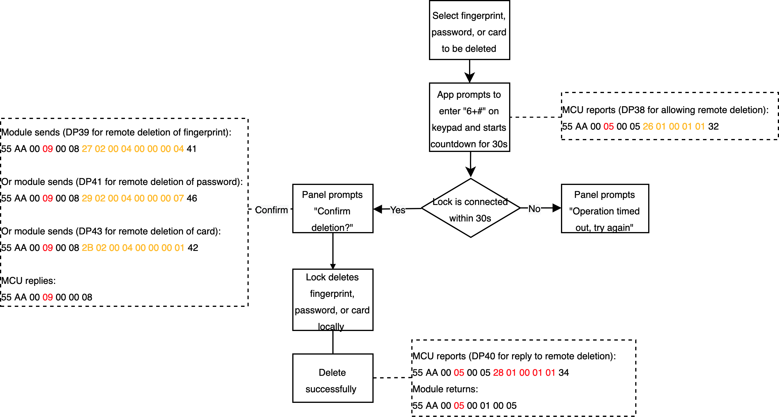
Delete unlocking methods on the app (Pro version only)
Scenario
Delete unlocking methods through the app, such as fingerprint, door card, and password.
Relevant DPs
- Allow remote deletion
- Delete fingerprints remotely
- Reply to remote deletion
- Delete passwords remotely
- Delete cards remotely
DP description
- Delete fingerprints, passwords, and cards remotely: The DP values are used to distinguish members, ranging from 0 to 999.
- The lock allows remote deletion and replies to remote deletion: Use the Bool type and MCU reports status.
Implementation process
Processes
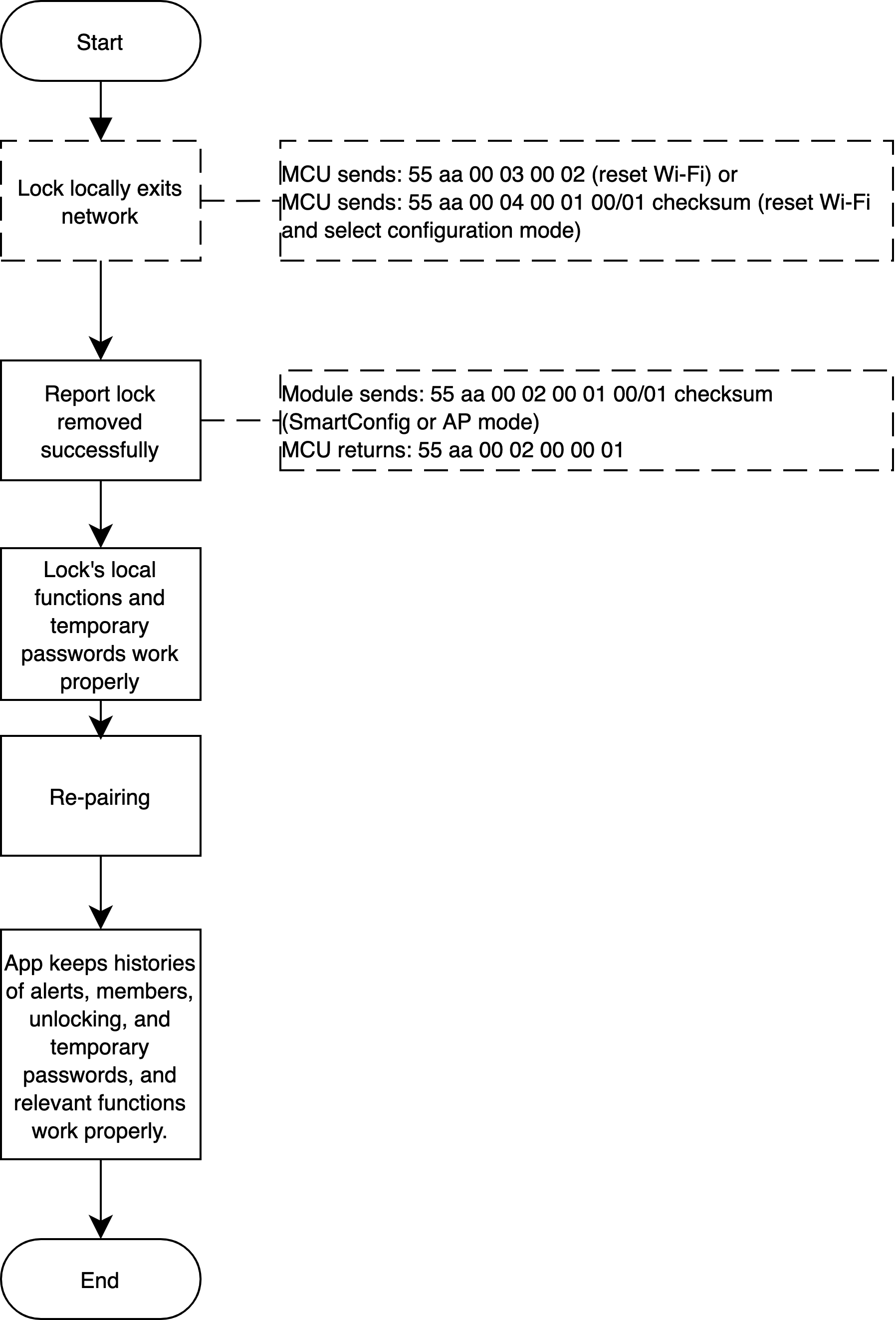
Locally exit network
Scenario
Lock locally exits network
Implementation logic
Press the keypad to let lock exit network. Reset Wi-Fi by 03 or 04 command, and the app displays successful removal of the lock. The lock’s local functionality and temporary password can still work properly.
When pairing locks again after removal, the app keeps previous histories of alerts, members, and unlocking operations, as well as temporary passwords. Relevant functionality can work properly.
Implementation process
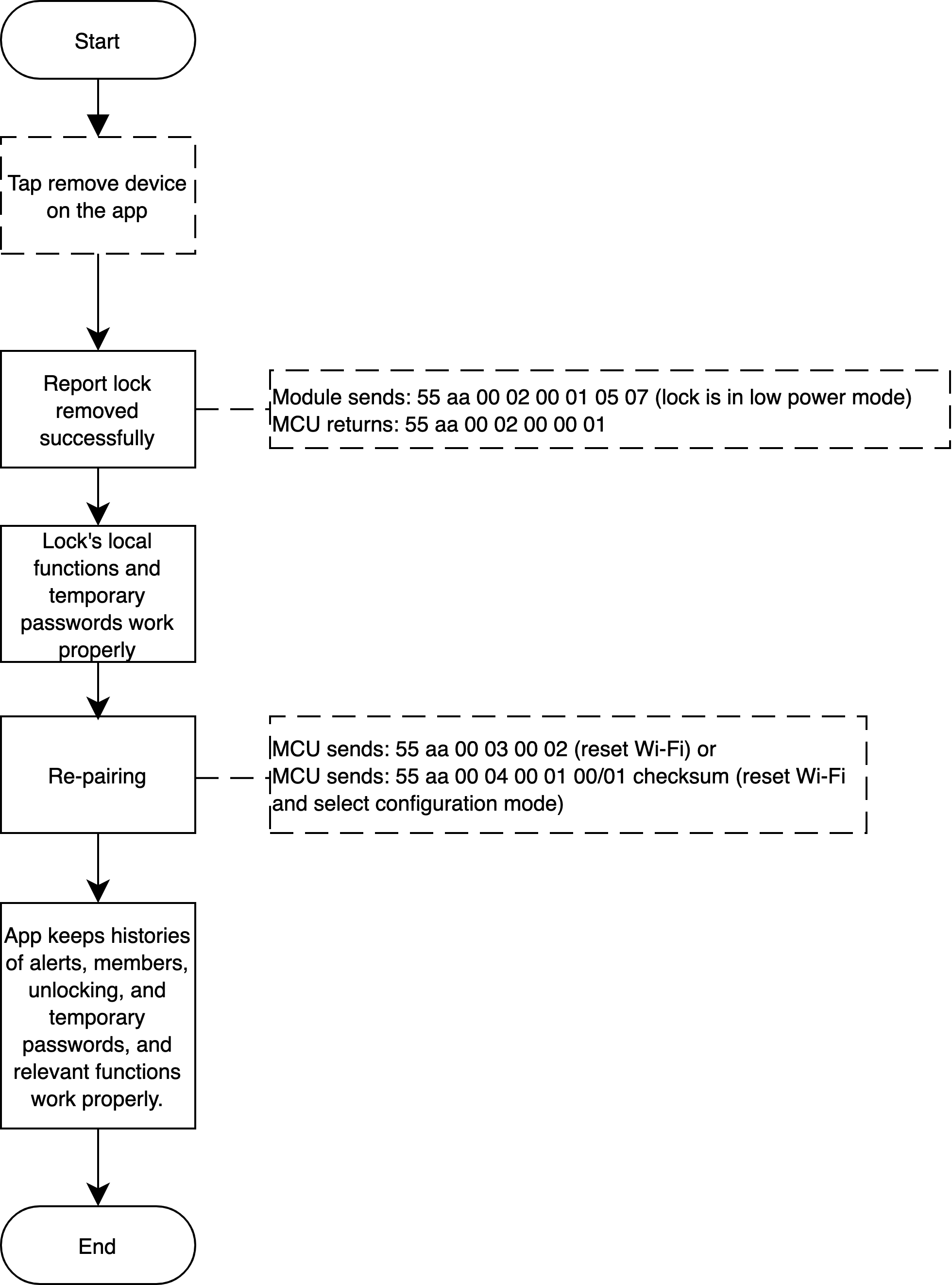
Exit network on the app
Scenario
Exit network with the app
Implementation logic
Select a lock and click Remove Device on the app, which does not affect local functionality and temporary password usage.
When pairing locks again after removal, the app keeps previous histories of alerts, members, and unlocking operations, as well as temporary passwords. Relevant functionality can work properly.
Implementation process
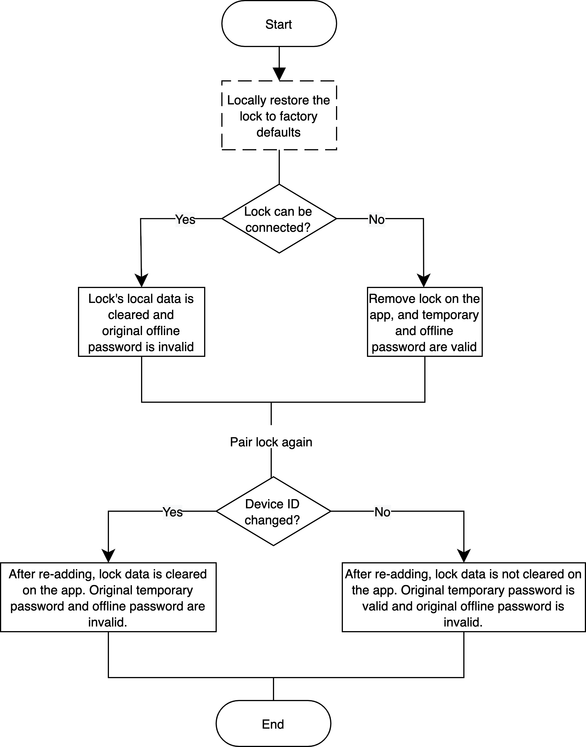
Locally restore factory defaults
Scenario
Locally restore the lock to factory defaults.
Implementation logic
The lock is connected
After locally restoring the lock to factory defaults, and before pairing again, local data on the SD card, fingerprints, passwords, faces, and temporary passwords will be cleared. Locks on the app can be removed, which is not the required operation. In the case of lock removal on the app, the module sends Wi-Fi reset protocols to the app, and the local factory reset is executed. Original offline passwords are invalid.
After pairing and adding the lock again, if the device ID remains unchanged (for the old baseline, Espressif 8266), the lock data such as the unlocking history and temporary passwords retain on the app. Original temporary passwords are available but offline passwords are invalid. If the device ID is changed and the lock is added again, the lock data will be cleared on the app. Both original temporary and offline passwords are invalid.
The lock is not connected
After locally restoring the lock to factory defaults, before pairing the lock again, the local data will be cleared. Locks on the app are not removed but the app cannot receive new data from the lock and control it. Original offline passwords are invalid.
After pairing and adding the lock again, if the device ID remains unchanged (for the old baseline, Espressif 8266), the original lock will be overridden. The lock’s record retains on the app. Original temporary passwords are available but offline passwords are invalid. If the device ID is changed and the lock is added again, the lock data will be cleared on the app. Both original temporary and offline passwords are invalid.
Implementation process
Restore factory defaults on the app
Scenario
Restore factory defaults on the app.
Implementation logic
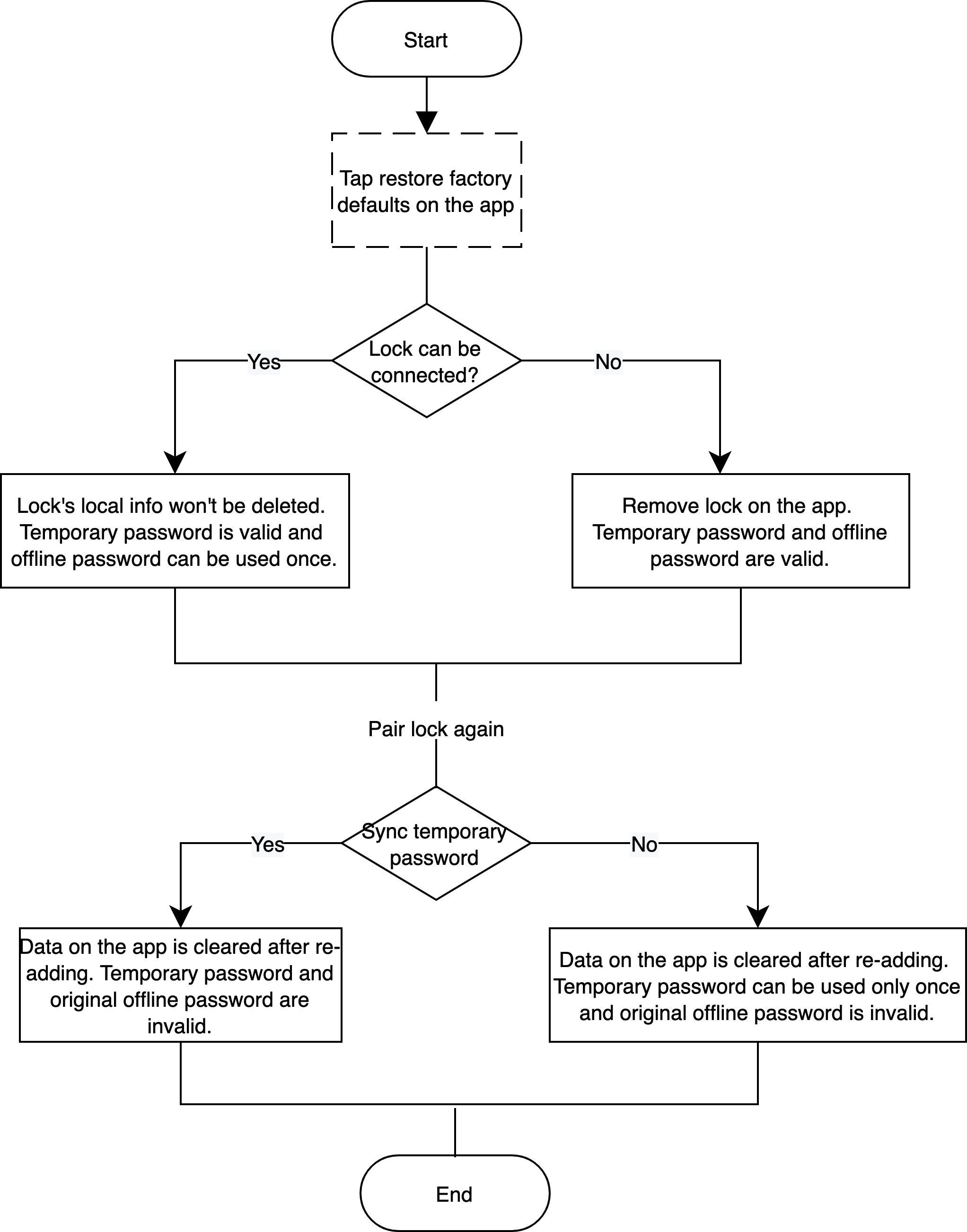
The lock is connected
Click Disconnect and wipe data on the app. Before pairing locks again, the data such as local information card, fingerprints, passwords, and faces will not be deleted. Temporary passwords are available and offline passwords are only valid one time.
If the temporary password list (empty list) is set to be synchronized after pairing the lock again, data on the app will be cleared. Temporary passwords and original offline passwords are unavailable. If such a synchronous mechanism is not used, all data on the app will be cleared after adding the lock again. Temporary passwords are only valid one time and previous offline passwords are unavailable.
The lock is not connected
Click Restore Factory Settings on the app. Before pairing the lock again, the lock has been removed from the app. Temporary and offline passwords are available.
If the temporary password list (empty list) is set to be synchronized after pairing the lock again, data on the app will be cleared after the lock is added again. Temporary passwords and previous offline passwords are unavailable. If such a synchronous mechanism is not used, all data on the app will be cleared after the lock is added again. Temporary passwords are only valid one time and original offline passwords are unavailable.
Implementation process
Alexa scenario linkage
Scenario
Link non-keepalive Wi-Fi lock with Alexa-enabled smart devices. For example, when the door is opened, Alexa-enabled lights or other devices are automatically turned on.
Relevant DPs
Locking status: lock_motor_state. Boolean type. Report status and send command. true indicates unlocking and false indicates locking.
Implementation logic
- Select
lock_motor_statewhen setting PID. This DP is used to determine the lock status by Alexa, and it must be reported accurately. - If unlocking from the outside, the MCU must report
lock_motor_state.trueindicates unlocking andfalseindicates locking. Ensure when the door is locked or automatically locked,lock_motor_stateis properly reported and the reported status must befalse. - Non-keepalive Wi-Fi locks only support Alexa Routines, that is, the lock can only be used as a trigger condition, not an execution condition.
- If locks can distinguish between unlocking from the outside and unlocking from the inside, Alexa Routines support scenarios where unlocking triggers lights or air conditioners on. For unlocking from the inside, it is recommended that
lock_motor_statenot be reported.
Locks support capturing picture
Scenario
Apply to picture transmission for locks with face recognition. Users can view who unlocks the door.
Related DPs
- DP 212 used to actively push messages: The MCU does not need to process it.
| Unlocking DP (ID of the DP for unlocking/alerts) | Unlocking time (seconds) | The number of pictures/videos (no more than 10) | Event pictures/video ID (2 x n) | Event reporting time (seconds) |
|---|---|---|---|---|
| 1 byte | 4 bytes | 1 byte | 2 bytes * n | 4 bytes |
Description:
- Unlocking DP: DP of unlocking record or alerts.
- Unlocking time: Time of DP for unlocking record reporting, which shall be consistent with the time of DP for unlocking.
- The number of events: The number of pictures reported for current events. Support one picture by default.
- Picture ID: The ID of the picture captured for current events. According to the picture ID generation rules defined by the MCU,
0x62also returns the picture ID. - Event reporting time: Indicate when the picture is uploaded. This time is also returned when the module reports the result of picture uploading with
0x62.
Note: The unlocking time and the event reporting time are identified by time. To clearly distinguish event records, you must strictly follow rules to write data and not modify data or convert time zone.
Implementation process
Processes
Note:
- Products with picture transmission function shall return
capcontent in the0x01product information query. - The module must return a successful network connection before reporting the picture status every time.
- Every time a picture status is reported, the
0x60command must be sent to notify the Wi-Fi module. - For the picture uploading, when the module returns failure (
0x62), if the picture is transmitted again, the uploading must be triggered from0x60.
Related protocols
0x08 for reporting record type data: This status is used to report unlocking and alert events.
0x60 for notifying event status: It is used to notify the Wi-Fi module. If picture uploading is involved, the module will enable picture transmission when it receives this command.
0x61 for uploading pictures: It is used to transmit pictures with the Wi-Fi module. The data transmission supports SPI or UART protocols. For the specific communication protocols, query the product information by 0x01.
0x62 for results of picture uploading: The module returns results of picture uploading by this command. When the module returns failure, if the picture is transmitted again, the uploading must be triggered from 0x60.
0x63 for getting picture uploading status: The MCU actively query picture transmission status for the current module.
Additional remarks
Time calibration
It is recommended that the lock should regularly and actively calibrate time with the cloud.
Related MCU commands: Get GMT/local time
OTA
MCU firmware OTA updates. Tuya Developer Platform only supports updates from an earlier version to a later version.
Related MCU commands: Request MCU firmware updates. Start updates. Transmit update package. The MCU returns the product information and the latest firmware version.
Wi-Fi module firmware updates. It is used when module updates are notified.
Related MCU commands: Request Wi-Fi module firmware updates.
Production test
It is used for production tests of locks.
Related MCU commands: Wi-Fi functional test.
Get Wi-Fi signals
This function is used in the debugging phase.
Related MCU commands: Check the signal strength of the currently connected router.
Alert settings
To send push notifications to the app, configure Device Notification on the Developer Platform.
Module information
- Recommended modules: If the board space is enough, XR1 is recommended. Onboard antenna and external antenna are both available to choose from.
- Module datasheet: Find the module details in the Hardware Develop step of product development on the Developer Platform.
- PCBA design: The rear part of the onboard antenna module is recommended to be hollowed out. The maximum current for the power supply is recommended to be 500 mA.
- Baud: Support 115200 and 9600.
- Module debugging assistant: Download the module debugging assistant in the Hardware Develop step of product development on the Developer Platform.
Is this page helpful?
YesFeedbackIs this page helpful?
YesFeedback


