WBRL Peephole Camera Protocol
This topic describes the communication protocol and data exchange for audio and video transmission between the peephole camera and the WBRL module.
Hardware description
Hardware connection
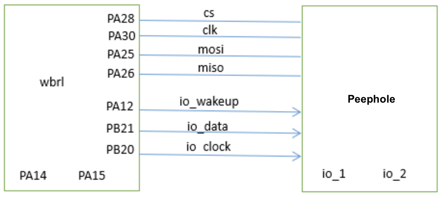
The following figure shows the connection between the WBRL module and the peephole hardware.
Pin definitions
| Type | Pin | Description |
|---|---|---|
| SPI pins | PA28 | Chip select |
| PA30 | Clock signal from the main, used by the sub to send and receive data. | |
| PA25 | Main out, sub in. | |
| PA26 | Main in, sub out. | |
| Special pins | PA12 | The wake-up pin, normally low. To wake up the peephole, pull up this pin for 250 milliseconds and then pull down it. When the peephole detects that this pin is high for 250 ms, it will wake up. Note: The peephole should not wake up upon detecting a single rising edge, which may occur due to a brief high signal from |
| PB21 | Data request. This pin is normally low. When the WBRL module is ready to receive data, it pulls this pin up and then down. The main sends data only when detecting a rising edge change on this pin. | |
| PB20 | Clock request. This pin is normally low. To send data, the WBRL module pulls this pin up and then down. When detecting a rising edge change, the main generates a clock on which the WBRL module sends data. |
SPI parameters
| Clock rate | Clock mode | Data transfer | Chip select | Data width | Main-sub setting |
|---|---|---|---|---|---|
| Up to 25 MHz (8 MHz recommended). | MODE0: Mode 0[CPOL=0,CPHA=0] |
MSB | Active low | 8 bits | The peephole is the main while the module is the sub. |
Notes
If possible, you can reserve one or two I/Os for future feature expansion.
How it works
Interaction
Data length
The WBRL module and the peephole communicate using a fixed-length data format of 3,872 bytes. If the packet length is less than 3,872 bytes, pad it with zeros after the payload.
Wake up
-
To wake up the peephole, the WBRL module pulls up PA12 for 500 milliseconds and then pulls it down. When the peephole detects that this pin is high for 500 ms, it will wake up. The WBRL module can wake up the peephole up to three times.
-
The WBRL module is the sub, while the peephole is the main. Therefore, the peephole cannot determine if the WBRL module is ready to read or write data. To avoid timing issues during data exchange, send data or clock signals only after the level on PB21 or PB20 changes.
The WBRL module cannot detect the peephole wake-up state, so when the peephole wakes up, it notifies the WBRL module by sending
0x63. -
After the peephole sends the command
0x63, if the WBRL module fails to send the clock pin change within the timeout, the peephole will resend0x63each time the WBRL module pulls up PB21.
Upload image, video, or audio
- The WBRL module responds to the command
0x63by pulling up PB20 to request image or video upload and reports its readiness. - The peephole operates based on the response to
0x63.- Not ready: The peephole continuously sends the command
0x63to check the readiness of the WBRL module until it is ready. - Ready: Streaming is ready.
- Failed: The peephole stops transmission and queries and then enters sleep mode.
- Not ready: The peephole continuously sends the command
- After the peephole receives a ready status from the WBRL module, it will send the command
0x61the next time PB21 is pulled up to transmit image or video data to the WBRL module. During this period, each time the WBRL module pulls up PB21, the peephole sends a data packet but cannot send data proactively. - After the image or video upload is completed, the WBRL module pulls up PB20 and sends the command
0x6Fto notify the peephole of completion. After receiving this notification, the peephole does not respond to the WBRL module and can enter sleep mode directly.
Send audio
- The mobile app sends audio to the device for two-way talk.
- After the WBRL module establishes a stream, it will pull up PB20 and send the command
0x68to the peephole before transmitting audio. During this period, each time the WBRL module pulls up PB20, the peephole sends a clock signal.
QR code pairing
- After waking up, the peephole sends the command
0x63to the module. - The WBRL module requests QR code information for pairing from the peephole, which waits for changes in the I/O pin.
- After the WBRL module retrieves PB21, the peephole sends the QR code information using the command
0x6Awithout waiting for a response from the module. - After the WBRL module receives the QR code information, it pulls up PB20 and notifies the peephole of process completion with the command
0x6F. After receiving this notification, the peephole does not respond to the WBRL module and can enter sleep mode directly.
Protocol list
(Optional) Query product information (0x01)
The peephole sends the following data.
| Field | Length (byte) | Description |
|---|---|---|
| Header | 2 | 0x55aa |
| Version | 1 | 0x00 |
| Command | 1 | 0x01 |
| Data length | 2 | N |
| Data | N | Product information, for example, {"p":"vHXEcqntLpkAlOsy"}. |
| Checksum | 1 | Start from the header, add up all the bytes, and then divide the sum by 256 to get the remainder. |
The module returns the following data.
| Field | Length (byte) | Description |
|---|---|---|
| Header | 2 | 0x55aa |
| Version | 1 | 0x00 |
| Command | 1 | 0x01 |
| Data length | 2 | 0001 |
| Data | 1 |
|
| Checksum | 1 | Start from the header, add up all the bytes, and then divide the sum by 256 to get the remainder. |
Get the PID
Initiate transmission (0x63)
The peephole only supports images and videos.
The peephole sends the following data.
| Field | Length (byte) | Description |
|---|---|---|
| Header | 2 | 0x55aa |
| Version | 1 | 0x00 |
| Command | 1 | 0x63 |
| Data length | 2 | 0x0006 |
| Get time type | 1 |
|
| Video resolution (defaulting to 0 for images) | 1 |
|
| Video type (defaulting to 0 for images) | 1 |
|
| Video frame rate (defaulting to 0 for images) | 1 | Set the actual frame rate of your peephole. 10 to 20 fps are supported. |
| Video bitrate (defaulting to 0 for images) | 2 | The following parameters are supported:
|
| Checksum | 1 | Start from the header, add up all the bytes, and then divide the sum by 256 to get the remainder. |
The peephole supports images, videos, and audio
The peephole sends the following data.
| Field | Length (byte) | Description |
|---|---|---|
| Header | 2 | 0x55aa |
| Version | 1 | 0x00 |
| Command | 1 | 0x63 |
| Data length | 2 | 0x0010 |
| Get time type | 1 |
|
| Video resolution (defaulting to 0 for images) | 1 |
|
| Video type (defaulting to 0 for images) | 1 |
|
| Video frame rate (defaulting to 0 for images) | 1 | Set the actual frame rate of your peephole. 10 to 20 fps are supported. |
| Video bitrate (defaulting to 0 for images) | 2 | The following parameters are supported:
|
| Audio type | 1 |
|
| Audio frame rate | 1 | Set the actual frame rate of your peephole. 10 to 20 fps are supported. |
| Audio sampling rate | 4 |
|
| Audio bit depth | 1 |
|
| Audio channel | 1 | Default to 0 (not in use yet) |
| Rotation angle | 1 |
|
| Weather schedule | 1 |
|
| Checksum | 1 | Start from the header, add up all the bytes, and then divide the sum by 256 to get the remainder. |
The WBRL module returns the following data
| Field | Length (byte) | Description |
|---|---|---|
| Header | 2 | 0x55aa |
| Version | 1 | 0x00 |
| Command | 1 | 0x63 |
| Data length | 2 | 0x000e |
| Current status | 1 |
|
| Event type | 1 |
|
| Maximum transmission unit | 4 | The maximum size of an image packet. If exceeded, the data will be fragmented for transmission. |
| Time data | 8 | The data length is eight bytes.
|
| Checksum | 1 | Start from the header, add up all the bytes, and then divide the sum by 256 to get the remainder. |
Upload audio and video (0x61)
The peephole sends the following data.
| Field | Length (byte) | Description |
|---|---|---|
| Header | 2 | 0x55aa |
| Version | 1 | 0x00 |
| Command | 1 | 0x61 |
| Data length | 2 | N + 5 |
| Image sequence number | 2 | Default to 0. When transferring multiple images, the sequence number increments from 0 with each transfer and resets to zero after completion. |
| Fragmentation flag | 1 |
|
| Fragmentation sequence number | 1 | The sequence number starts at 0 and increments sequentially. |
| Frame format | 1 |
|
| Data | N | Data |
| Checksum | 1 | Start from the header, add up all the bytes, and then divide the sum by 256 to get the remainder. |
Send audio (0x68)
The module sends the following data.
| Field | Length (byte) | Description |
|---|---|---|
| Header | 2 | 0x55aa |
| Version | 1 | 0x00 |
| Command | 1 | 0x68 |
| Data length | 2 | N + 9 |
| Audio type | 1 |
|
| Reserved fields | 8 | The field must be set to 0. |
| Data | N | Audio data |
| Checksum | 1 | Start from the header, add up all the bytes, and then divide the sum by 256 to get the remainder. |
Complete transmission (0x6F)
After the audio and video transmission is complete, the module will notify the peephole of entering sleep mode with the command 0x6F to conserve power.
The module sends the following data.
| Field | Length (byte) | Description |
|---|---|---|
| Header | 2 | 0x55aa |
| Version | 1 | 0x00 |
| Command | 1 | 0x6F |
| Data length | 2 | 0x0001 |
| Status | 1 | 0x00: Streaming ends and the peephole enters sleep mode. |
| Checksum | 1 | Start from the header, add up all the bytes, and then divide the sum by 256 to get the remainder. |
The peephole returns the following data.
| Field | Length (byte) | Description |
|---|---|---|
| Header | 2 | 0x55aa |
| Version | 1 | 0x00 |
| Command | 1 | 0x6F |
| Data length | 0 | 0x0000 |
| Data | None | |
| Checksum | 1 | Start from the header, add up all the bytes, and then divide the sum by 256 to get the remainder. |
QR code pairing (0x6A)
The peephole sends the following data.
| Field | Length (byte) | Description |
|---|---|---|
| Header | 2 | 0x55aa |
| Version | 1 | 0x00 |
| Command | 1 | 0x6A |
| Data length | 2 | N |
| Data | N | {"p":"12345678","s":"ydc","t":"AZJ5zpswTfpr_0"} |
| Checksum | 1 | Start from the header, add up all the bytes, and then divide the sum by 256 to get the remainder. |
The module returns the following data.
| Field | Length (byte) | Description |
|---|---|---|
| Header | 2 | 0x55aa |
| Version | 1 | 0x00 |
| Command | 1 | 0x6A |
| Data length | 2 | 0x0001 |
| Data | 1 |
|
| Checksum | 1 | Start from the header, add up all the bytes, and then divide the sum by 256 to get the remainder. |
Device testing (0x6E)
The module sends the following data.
| Field | Length (byte) | Description |
|---|---|---|
| Header | 2 | 0x55aa |
| Version | 1 | 0x00 |
| Command | 1 | 0x6E |
| Data length | 2 | 4 + N |
| Subcommand | 1 | 0x00 (reserved) |
| Wi-Fi scanning results | 1 |
|
| rssi | 1 | The signal strength percentage of the scanned router, ranging from 0 to 100. |
| Length of firmware version number | 1 | The byte size of the firmware version number. |
| Firmware version number | N | A variable-length string, such as 1.0.0. |
| Checksum | 1 | Start from the header, add up all the bytes, and then divide the sum by 256 to get the remainder. |
The peephole returns the following data.
| Field | Length (byte) | Description |
|---|---|---|
| Header | 2 | 0x55aa |
| Version | 1 | 0x00 |
| Command | 1 | 0x6E |
| Data length | 2 | 0x0000 |
| Data | 0 | None |
| Checksum | 1 | Start from the header, add up all the bytes, and then divide the sum by 256 to get the remainder. |
Testing process
- The door lock PCB initiates a test with the command
0xF0. - After receiving
0xF0, the module performs a test, wakes up the peephole, and notifies it to enter testing mode with the command0x63via SPI. - Upon receiving
0x63, the peephole performs the specified test. - After the module completes testing, it notifies the peephole of the results via SPI using
0x6e, which then displays relevant information including the module’s firmware version and Wi-Fi signal strength. The module then enters deep sleep mode, enabling you to monitor the overall power consumption.
Get weather service (0x85)
- The peephole requests weather information using the command
0x85. - Upon receiving the command, the module verifies the weather parameters and then sends the weather data to the peephole using the command
0x86.
The peephole sends the following data.
| Field | Length (byte) | Description |
|---|---|---|
| Header | 2 | 0x55aa |
| Version | 1 | 0x00 |
| Command | 1 | 0x85 |
| Data length | 2 | 0x0005 |
| Get weather type | 4 | See Appendix 2. |
| Number of forecast days | 1 | The number of forecast days, ranging from one to seven. |
| Checksum | 1 | Start from the header, add up all the bytes, and then divide the sum by 256 to get the remainder. |
The module returns the following data.
| Field | Length (byte) | Description |
|---|---|---|
| Header | 2 | 0x55aa |
| Version | 1 | 0x00 |
| Command | 1 | 0x85 |
| Data length | 2 | 0x0001 |
| Data | 1 |
|
| Checksum | 1 | Start from the header, add up all the bytes, and then divide the sum by 256 to get the remainder. |
Send weather data (0x86)
The module sends the following data.
| Field | Length (byte) | Description |
|---|---|---|
| Header | 2 | 0x55aa |
| Version | 1 | 0x00 |
| Command | 1 | 0x86 |
| Data length | 2 | N (KDTLD + KDTLD +…) |
| Data | N | Response in the KDTLD format. |
| Checksum | 1 | Start from the header, add up all the bytes, and then divide the sum by 256 to get the remainder. |
Field description:
K(4 bytes): The name of the request parameter. See Appendix 1.D(1 byte): The number of forecast days.T(1 byte): The parameter type.L(2 bytes): The length of one KDTLD.D: The payload.
Switch video mode (0x88)
Switch between camera views on the mobile app. See Appendix 5 for details.
The module sends the following data.
| Field | Length (byte) | Description |
|---|---|---|
| Header | 2 | 0x55aa |
| Version | 1 | 0x00 |
| Command | 1 | 0x88 |
| Data length | 2 | N |
| Data | N | Data[0]: 0x00 to 0xFF.
|
| Checksum | 1 | Start from the header, add up all the bytes, and then divide the sum by 256 to get the remainder. |
The peephole returns the following data.
| Field | Length (byte) | Description |
|---|---|---|
| Header | 2 | 0x55aa |
| Version | 1 | 0x00 |
| Command | 1 | 0x88 |
| Data length | 2 | N |
| Data | N |
|
| Checksum | 1 | Start from the header, add up all the bytes, and then divide the sum by 256 to get the remainder. |
Field description:
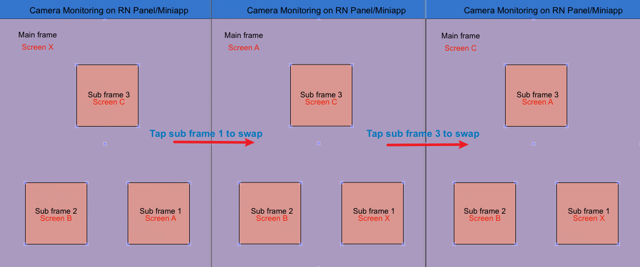
When switching to another screen, users tap the target sub frame, which will be swapped with the current main frame. Consequently, the RN panel and miniapp send the ID of the sub frame to the device.
If you do not display the position label, the device only responds with the status field and 2-byte FFFF. Otherwise, include the position type for the corresponding channel.
The full data supports N channels, defined as follows:
| Main frame (1 + 1 byte) |
Sub frame 1 (1 + 1 byte) |
… | Sub frame n (1 + 1 byte) |
|---|---|---|---|
| ID + Location type | ID + Location type | ID + Location type |
The code for location type is defined as follows:
0x01: Main0x02: Sub0x03: Front0x04: Back0x05: Up0x06: Down0x07: Left0x08: Right
Transmit raw data (0x90)
Transmit raw data between the lock PCB and the peephole camera.
The module sends the following data.
| Field | Bytes | Description |
|---|---|---|
| Header | 2 | 0x55aa |
| Version | 1 | 0x00 |
| Command | 1 | 0x90 |
| Data length | 2 | N |
| Data | N | Custom information, not parsed by the module |
| Checksum | 1 | Start from the header, add up all the bytes, and then divide the sum by 256 to get the remainder |
The peephole returns the following data.
| Field | Bytes | Description |
|---|---|---|
| Header | 2 | 0x55aa |
| Version | 1 | 0x00 |
| Command | 1 | 0x90 |
| Data length | 2 | N |
| Data | N | Custom information, not parsed by the module |
| Checksum | 1 | Start from the header, add up all the bytes, and then divide the sum by 256 to get the remainder |
Appendix
Appendix 1: Weather parameters
| Parameter | Code | Type | Weather forecast |
|---|---|---|---|
| Temperature | 1 << 0 | Integer | No |
| High temperature | 1 << 1 | Integer | Yes |
| Low temperature | 1 << 2 | Integer | Yes |
| Humidity | 1 << 3 | Integer | Yes |
| Weather condition | 1 << 4 | A string. See Appendix 3. | Yes |
| Pressure | 1 << 5 | Integer | Yes |
| Sensible temperature | 1 << 6 | Integer | No |
| Ultraviolet (UV) index | 1 << 7 | Integer | Yes |
| Sunrise | 1 << 8 | String (format example: 2017-04-24 05:24) | Yes |
| Sunset | 1 << 9 | String (format example: 2017-04-24 18:32) | Yes |
| Wind speed | 1 << 12 | String (format example: 0.9) | Yes |
| Wind direction | 1 << 13 | A string. See Appendix 4. | Yes |
| Wind speed scale/level | 1 << 14 | Integer | No |
| Air quality index | 1 << 15 | Integer | No |
| PM10 (inhalable particulate matter) | 1 << 16 | Integer | No |
| PM2.5 (fine particulate matter) | 1 << 17 | Integer | No |
| Ozone level | 1 << 18 | Integer | No |
| Nitrogen dioxide level | 1 << 19 | Integer | No |
| Carbon monoxide level | 1 << 20 | Integer | No |
| Sulfur dioxide level | 1 << 21 | Integer | No |
Appendix 2: Weather parameter types
WKT_TEMP        = (1 << 0),     /**< temperature. */
WKT_THIHG       = (1 << 1),     /**< high temperature. */
WKT_TLOW        = (1 << 2),     /**< low temperature. */
WKT_HUMIDITY    = (1 << 3),     /**< humidity. */
WKT_CONDITIONNUM   = (1 << 4),     /**< weather condition. */
WKT_PRESSURE    = (1 << 5),     /**< pressure. */
WKT_REALFEEL    = (1 << 6),     /**< sensible temperature. */
WKT_UVI         = (1 << 7),     /**< uvi. */
WKT_SUNRISE     = (1 << 8),     /**< sunrise. */
WKT_SUNSET      = (1 << 9),     /**< sunset. */
WKT_UNIX        = (1 << 10),    /**< unix time, used with sunrise and sunset. */
WKT_LOCAL       = (1 << 11),    /**< local time, used with sunrise and sunset. */
WKT_WINDSPEED   = (1 << 12),    /**< wind speed. */
WKT_WINDDIR     = (1 << 13),    /**< wind direction. */
WKT_WINDLEVEL   = (1 << 14),    /**< wind speed scale/level. */
WKT_AQI         = (1 << 15),    /**< aqi. */
WKT_PM10        = (1 << 16),    /**< pm10. */
WKT_PM25        = (1 << 17),    /**< pm2.5. */
WKT_O3          = (1 << 18),    /**< o3. */
WKT_NO2         = (1 << 19),    /**< no2. */
WKT_CO          = (1 << 20),    /**< co. */
WKT_SO2         = (1 << 21),    /**< so2. */
Appendix 3: Weather conditions
ASCII code w.conditionNum |
Hexadecimal value | Weather conditions |
|---|---|---|
| 120 | 31 32 30 | Sunny |
| 101 | 31 30 31 | Heavy rain |
| 102 | 31 30 32 | Thunderstorm |
| 103 | 31 30 33 | Sandstorm |
| 104 | 31 30 34 | Light snow |
| 105 | 31 30 35 | Snow |
| 106 | 31 30 36 | Freezing fog |
| 107 | 31 30 37 | Rainstorm |
| 108 | 31 30 38 | Isolated shower |
| 109 | 31 30 39 | Dust |
| 110 | 31 31 30 | Thunder and lightning |
| 111 | 31 31 31 | Light shower |
| 112 | 31 31 32 | Rain |
| 113 | 31 31 33 | Sleet |
| 114 | 31 31 34 | Dust devil |
| 115 | 31 31 35 | Ice pellets |
| 116 | 31 31 36 | Strong sandstorm |
| 117 | 31 31 37 | Sand blowing |
| 118 | 31 31 38 | Light to moderate rain |
| 119 | 31 31 39 | Mostly clear |
| 121 | 31 32 31 | Fog |
| 122 | 31 32 32 | Shower |
| 123 | 31 32 33 | Heavy shower |
| 124 | 31 32 34 | Heavy snow |
| 125 | 31 32 35 | Extreme rainstorm |
| 126 | 31 32 36 | Blizzard |
| 127 | 31 32 37 | Hail |
| 128 | 31 32 38 | Light to moderate snow |
| 129 | 31 32 39 | Partly cloudy |
| 130 | 31 33 30 | Light snow shower |
| 131 | 31 33 31 | Moderate snow |
| 132 | 31 33 32 | Overcast |
| 133 | 31 33 33 | Needle ice |
| 134 | 31 33 34 | Downpour |
| 136 | 31 33 36 | Thundershower and hail |
| 137 | 31 33 37 | Freezing rain |
| 138 | 31 33 38 | Snow shower |
| 139 | 31 33 39 | Light rain |
| 140 | 31 34 30 | Haze |
| 141 | 31 34 31 | Moderate rain |
| 142 | 31 34 32 | Cloudy |
| 143 | 31 34 33 | Thundershower |
| 144 | 31 34 34 | Moderate to heavy rain |
| 145 | 31 34 35 | Heavy rain to rainstorm |
| 146 | 31 34 36 | Clear |
Appendix 4: Wind direction code
| Code (string) | Hexadecimal value | Description |
|---|---|---|
| N | 4e | North |
| NNE | 4e 4e 45 | Northeast by north |
| NE | 4e 45 | Northeast |
| ENE | 45 4e 45 | Northeast by east |
| E | 45 | East |
| ESE | 45 53 45 | Southeast by east |
| SE | 53 45 | Southeast |
| SSE | 53 53 45 | Southeast by south |
| S | 53 | South |
| SSW | 53 53 57 | Southwest by south |
| SW | 53 57 | Southwest |
| WSW | 57 53 57 | Southwest by west |
| W | 57 | West |
| WNW | 57 4e 57 | Northwest by west |
| NW | 4e 57 | Northwest |
| NNW | 4e 4e 57 | Northwest by north |
Appendix 5: Multi-camera switching
Sub frame position
The configuration options will be available as a cloud feature in the future, enabling you to customize display positions.
No position labels displayed
Position labels displayed
Additionally, display the camera position, as shown in the small green box below.
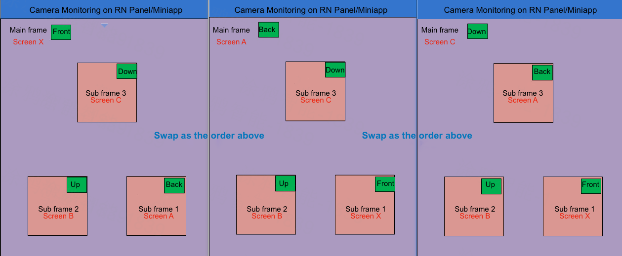
The full data for switching between screens with position labels in the sequence shown in the image above.
| Switch | Main frame-0 | Sub frame-1 | Sub frame-2 | Sub frame-3 | Full data in hex |
|---|---|---|---|---|---|
| Default | Front | Back | Up | Down | 0003 0104 0205 0306 |
| First switching | Back | Front | Up | Down | 0004 0103 0205 0306 |
| Second switching | Down | Front | Up | Back | 0006 0103 0205 0304 |
Is this page helpful?
YesFeedbackIs this page helpful?
YesFeedback


