WBRU Peephole Camera Protocol
This topic describes the communication protocol and data exchange for audio and video transmission between the peephole camera and the WBRU module.
Hardware description
Hardware interfaces
The hardware for the door lock with camera includes three components: the lock’s MCU, peephole camera, and Wi-Fi module. The necessary hardware interfaces are listed in the table below.
| Interface | Name | Description | WBRU pin | Notes |
|---|---|---|---|---|
| Peephole’s SPI | CS/SCK/MOSI/MISO | The SPI interface for communication between the module and the peephole, such as audio and video transmission. | PA7/PA8/PA9/PA10 | As needed |
| Peephole’s UART | TXD/RXD/GND | The UART interface for communication between the module and the peephole. For example, send downstream data and put the peephole to sleep. | PA3/PA2/GND | As needed |
| Peephole’s wake-up GPIO | WAKEUP_IO | Pull up the pin with a monopulse signal for 250 milliseconds to wake up the peephole. | PA4 | Optional |
| Peephole’s resumable download GPIO | NOTIFY_IO | Notify the peephole of sending the next packet with a falling edge pulse. | PA19 | Optional |
| Lock’s MCU UART | TXD/RXD/GND | Used for UART transmission between the module and lock’s MCU. | PA14/PA13/GND | Required |
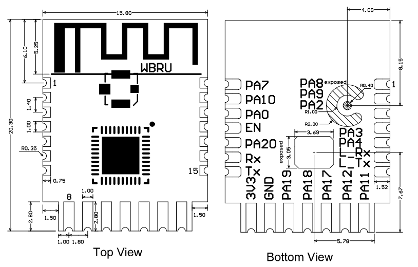
The pinout for the WBRU module is as follows. See WBRU Datasheet for details.
Hardware solutions
The hardware peripherals support various peephole solutions, including image upload only, video upload, and video talk. This section compares the typical solutions.
| Solution | Capability | Required hardware interface | Description |
|---|---|---|---|
| Single UART | Image upload only | Lock’s MCU UART | The peephole is connected to the lock’s MCU which the module only communicates with. |
| Single SPI | Image upload only | SPI | The lock’s MCU wakes up the peephole by powering it on. The peephole’s SPI sends the command 0x67 to request the readiness for the next packet. |
| SPI + single I/O | Image and video upload | SPI + notify_io | The lock’s MCU wakes up the peephole by powering it on. The readiness for the next packet is notified via notify_io. |
| SPI + dual I/Os | Image and video upload | SPI + wakeup_io + notify_io | Wake up the peephole with wakeup_io. The readiness for the next packet is notified via notify_io. |
| SPI + peephole’s UART + wake-up I/O | Image upload and video talk | SPI + peephole’s UART + wakeup_io | Wake up the peephole with wakeup_io. The readiness for the next packet is notified via UART. |
How each solution works:
Single UART
Single SPI
SPI + single I/O
SPI + dual I/Os
SPI + peephole’s UART + I/O (video talk)
UART parameters
| Baud rate | Data bit | Parity bit | Stop bit | Data flow control |
|---|---|---|---|---|
| Peephole’s UART: 115200 bps Lock’s MCU UART: 115200 or 9600 bps |
8 | None | 1 | None |
SPI parameters
| Clock rate | Clock mode | Data transfer | Chip select | Data width | Main-sub setting |
|---|---|---|---|---|---|
| 4 MHz | MODE0: Mode 0[CPOL=0,CPHA=0] |
MSB | Active low | 8 bits | The peephole is the main while the module is the sub. |
Software implementation
Implement the following logic for the peephole:
- Each time the peephole wakes up, it checks the module status with the command
0x63. Audio and video data can only be transmitted via SPI when the module is ready. - A large volume of audio and video data must be transmitted using SPI instead of UART.
- Use DMA mode for SPI transmission to enhance efficiency whenever possible.
- The peephole can request time sync based on the module’s response to the command
0x63. - If audio is supported, implement the command to send audio data.
- If QR code scanning is supported, implement the related commands.
The diagram below illustrates data exchange in several typical scenarios.
Protocols
Frame format
| Field | Bytes | Description |
|---|---|---|
| Header | 2 | 0x55AA |
| Version | 1 | It is used for updates and extensions, defaulting to pv: 0x00. |
| Command | 1 | The frame type. |
| Data length | 2 | Upper 8 bits Lower 8 bits |
| Data | N | - |
| Checksum | 1 | Start from the header, add up all the bytes, and then divide the sum by 256 to get the remainder. |
Field description:
- Byte order: big endian. All data greater than one byte is transmitted in big-endian format.
- Version: used to extend features. To ensure compatibility with legacy versions, this field defaults to
0x00, and the module does not validate it.
Command index
| Command name | Command | Direction | Notes |
|---|---|---|---|
| Initiate transmission | 0x63 | Peephole to module | - |
| Send audio and video data | 0x61 | Peephole to module | No response |
| Query status | 0x67 | Peephole to module | The peephole’s SPI requests the readiness for the next packet. |
| Notify peephole to upload data | 0x69 | Module to peephole | The peephole’s UART receives the command, without an acknowledgment. |
| Send audio data | 0x68 | Module to peephole | No response |
| Notify completion of streaming | 0x6F | Module to peephole | - |
| QR code pairing | 0x6A | Peephole to module | - |
| Trigger image capture | 0x64 | MCU to module | This command is for the lock’s MCU, not the peephole. |
| Notify image capture results | 0x62 | Module to MCU | This command is for the lock’s MCU, not the peephole. |
| Trigger image upload | 0x60 | MCU to module | This command is for the lock’s MCU, not the peephole. The predecessor of the command 0x64. |
Command implementation by solution
| Command | Single UART | Single SPI | SPI + single I/O | SPI + dual I/Os | SPI + UART + I/O | |||||||||||||||||||||||||||||||||||||||||||||||||||||||||||||||||||||||||||||||||||||||||||||||||||||||||||||||||||||||||||||||||||||||||||||||||||||||||||||||||||||||||||||||||||||||||||||||||||||||||||||||||||||||||||||||||||||||||||||||||||||||||||||||||||||||||||||||||||||||||||||||||||||||||||||||||||||||||||||||||||||||||||||||||||||||||||||||||||||||||||||||||||||||||||||||||||||||||||||||||||||||||||||||||||||||||||||||||||||||||||||||||||||||||||||||||||||||||||||
|---|---|---|---|---|---|---|---|---|---|---|---|---|---|---|---|---|---|---|---|---|---|---|---|---|---|---|---|---|---|---|---|---|---|---|---|---|---|---|---|---|---|---|---|---|---|---|---|---|---|---|---|---|---|---|---|---|---|---|---|---|---|---|---|---|---|---|---|---|---|---|---|---|---|---|---|---|---|---|---|---|---|---|---|---|---|---|---|---|---|---|---|---|---|---|---|---|---|---|---|---|---|---|---|---|---|---|---|---|---|---|---|---|---|---|---|---|---|---|---|---|---|---|---|---|---|---|---|---|---|---|---|---|---|---|---|---|---|---|---|---|---|---|---|---|---|---|---|---|---|---|---|---|---|---|---|---|---|---|---|---|---|---|---|---|---|---|---|---|---|---|---|---|---|---|---|---|---|---|---|---|---|---|---|---|---|---|---|---|---|---|---|---|---|---|---|---|---|---|---|---|---|---|---|---|---|---|---|---|---|---|---|---|---|---|---|---|---|---|---|---|---|---|---|---|---|---|---|---|---|---|---|---|---|---|---|---|---|---|---|---|---|---|---|---|---|---|---|---|---|---|---|---|---|---|---|---|---|---|---|---|---|---|---|---|---|---|---|---|---|---|---|---|---|---|---|---|---|---|---|---|---|---|---|---|---|---|---|---|---|---|---|---|---|---|---|---|---|---|---|---|---|---|---|---|---|---|---|---|---|---|---|---|---|---|---|---|---|---|---|---|---|---|---|---|---|---|---|---|---|---|---|---|---|---|---|---|---|---|---|---|---|---|---|---|---|---|---|---|---|---|---|---|---|---|---|---|---|---|---|---|---|---|---|---|---|---|---|---|---|---|---|---|---|---|---|---|---|---|---|---|---|---|---|---|---|---|---|---|---|---|---|---|---|---|---|---|---|---|---|---|---|---|---|---|---|---|---|---|---|---|---|---|---|---|---|---|---|---|---|---|---|---|---|---|---|---|---|---|---|---|---|---|---|---|---|---|---|---|---|---|---|---|---|---|---|---|---|---|---|---|---|---|---|---|---|---|---|---|---|---|---|---|---|---|---|---|---|---|---|---|---|---|---|---|---|---|---|---|---|---|---|---|
| 0x63 | ✔ | ✔ | ✔ | ✔ | ✔ | |||||||||||||||||||||||||||||||||||||||||||||||||||||||||||||||||||||||||||||||||||||||||||||||||||||||||||||||||||||||||||||||||||||||||||||||||||||||||||||||||||||||||||||||||||||||||||||||||||||||||||||||||||||||||||||||||||||||||||||||||||||||||||||||||||||||||||||||||||||||||||||||||||||||||||||||||||||||||||||||||||||||||||||||||||||||||||||||||||||||||||||||||||||||||||||||||||||||||||||||||||||||||||||||||||||||||||||||||||||||||||||||||||||||||||||||||||||||||||||
| 0x61 | ✔ | ✔ | ✔ | ✔ | ✔ | |||||||||||||||||||||||||||||||||||||||||||||||||||||||||||||||||||||||||||||||||||||||||||||||||||||||||||||||||||||||||||||||||||||||||||||||||||||||||||||||||||||||||||||||||||||||||||||||||||||||||||||||||||||||||||||||||||||||||||||||||||||||||||||||||||||||||||||||||||||||||||||||||||||||||||||||||||||||||||||||||||||||||||||||||||||||||||||||||||||||||||||||||||||||||||||||||||||||||||||||||||||||||||||||||||||||||||||||||||||||||||||||||||||||||||||||||||||||||||||
| 0x67 | ✖ | ✔ | ✖ | ✖ | ✖ | |||||||||||||||||||||||||||||||||||||||||||||||||||||||||||||||||||||||||||||||||||||||||||||||||||||||||||||||||||||||||||||||||||||||||||||||||||||||||||||||||||||||||||||||||||||||||||||||||||||||||||||||||||||||||||||||||||||||||||||||||||||||||||||||||||||||||||||||||||||||||||||||||||||||||||||||||||||||||||||||||||||||||||||||||||||||||||||||||||||||||||||||||||||||||||||||||||||||||||||||||||||||||||||||||||||||||||||||||||||||||||||||||||||||||||||||||||||||||||||
| 0x69 | ✖ | ✖ | ✖ | ✖ | ✔ | |||||||||||||||||||||||||||||||||||||||||||||||||||||||||||||||||||||||||||||||||||||||||||||||||||||||||||||||||||||||||||||||||||||||||||||||||||||||||||||||||||||||||||||||||||||||||||||||||||||||||||||||||||||||||||||||||||||||||||||||||||||||||||||||||||||||||||||||||||||||||||||||||||||||||||||||||||||||||||||||||||||||||||||||||||||||||||||||||||||||||||||||||||||||||||||||||||||||||||||||||||||||||||||||||||||||||||||||||||||||||||||||||||||||||||||||||||||||||||||
| 0x68 | ✖ | ✖ | ✖ | ✖ | ✔ | |||||||||||||||||||||||||||||||||||||||||||||||||||||||||||||||||||||||||||||||||||||||||||||||||||||||||||||||||||||||||||||||||||||||||||||||||||||||||||||||||||||||||||||||||||||||||||||||||||||||||||||||||||||||||||||||||||||||||||||||||||||||||||||||||||||||||||||||||||||||||||||||||||||||||||||||||||||||||||||||||||||||||||||||||||||||||||||||||||||||||||||||||||||||||||||||||||||||||||||||||||||||||||||||||||||||||||||||||||||||||||||||||||||||||||||||||||||||||||||
| 0x6F | ✖ | ✖ | ✖ | ✖ | ✔ | |||||||||||||||||||||||||||||||||||||||||||||||||||||||||||||||||||||||||||||||||||||||||||||||||||||||||||||||||||||||||||||||||||||||||||||||||||||||||||||||||||||||||||||||||||||||||||||||||||||||||||||||||||||||||||||||||||||||||||||||||||||||||||||||||||||||||||||||||||||||||||||||||||||||||||||||||||||||||||||||||||||||||||||||||||||||||||||||||||||||||||||||||||||||||||||||||||||||||||||||||||||||||||||||||||||||||||||||||||||||||||||||||||||||||||||||||||||||||||||
| 0x6A | ✖ | ✔ | ✔ | ✔ | ✔ | |||||||||||||||||||||||||||||||||||||||||||||||||||||||||||||||||||||||||||||||||||||||||||||||||||||||||||||||||||||||||||||||||||||||||||||||||||||||||||||||||||||||||||||||||||||||||||||||||||||||||||||||||||||||||||||||||||||||||||||||||||||||||||||||||||||||||||||||||||||||||||||||||||||||||||||||||||||||||||||||||||||||||||||||||||||||||||||||||||||||||||||||||||||||||||||||||||||||||||||||||||||||||||||||||||||||||||||||||||||||||||||||||||||||||||||||||||||||||||||
| 0x60 | ✔ | ✖ | ✖ | ✖ | ✖ | |||||||||||||||||||||||||||||||||||||||||||||||||||||||||||||||||||||||||||||||||||||||||||||||||||||||||||||||||||||||||||||||||||||||||||||||||||||||||||||||||||||||||||||||||||||||||||||||||||||||||||||||||||||||||||||||||||||||||||||||||||||||||||||||||||||||||||||||||||||||||||||||||||||||||||||||||||||||||||||||||||||||||||||||||||||||||||||||||||||||||||||||||||||||||||||||||||||||||||||||||||||||||||||||||||||||||||||||||||||||||||||||||||||||||||||||||||||||||||||
| Field | Bytes | Description |
|---|---|---|
| Header | 2 | 0x55aa |
| Version | 1 | 0x00 |
| Command | 1 | 0x63 |
| Data length | 2 | 0x0006 + N. N can be 0x00 or 0x0A.
|
| Data | Data[0]: The time type.
Data[4 to 5]: The video bitrate.
Data[8 to 11]: The audio sampling rate.
Data[14]: The angle of rotation.
0x00. |
|
| Checksum | 1 | Start from the header, add up all the bytes, and then divide the sum by 256 to get the remainder. |
The module returns the following data.
| Field | Bytes | Description |
|---|---|---|
| Header | 2 | 0x55aa |
| Version | 1 | 0x00 |
| Command | 1 | 0x63 |
| Data length | 2 | 0x000E |
| Data | 14 | Data[0]: The current status.
Data[6]: Whether the time data is retrieved.
0x00 indicates the year 2000. Data[8]: indicates the month, ranging from 1 to 12. Data[9]: indicates the day, ranging from 1 to 31. Data[10]: indicates the hour, ranging from 0 to 23. Data[11]: indicates the minute, ranging from 0 to 59. Data[12]: indicates the second, ranging from 0 to 59. Data[13]: indicates the day of the week, ranging from 1 to 7. 1 indicates Monday. |
| Checksum | Start from the header, add up all the bytes, and then divide the sum by 256 to get the remainder. |
Example
-
Image or video upload only, 320 × 240 resolution, video type of MJPEG, video frame rate of 15 fps, video bitrate of 1 Mbit/s, request for GMT.
55 aa 00 63 00 06 01 00 03 0F 04 00 sum -
Audio and video, video parameters as above, audio type of G.711 A-law, audio frame rate of 15 fps, sampling rate of 8 kbit/s, audio bit depth of 8 bits, default audio channel, default angle of rotation.
55 aa 00 63 00 10 01 00 03 0F 04 00 6A 0F 00 00 1F 40 08 00 00 00 sum -
The module returns the following data.
55 aa 00 63 00 0e 01 02 00 00 02 00 01 xx xx xx xx xx xx xx sum. The status is Connecting to the Network, and live streaming is initiated.55 aa 00 63 00 0e 02 02 00 00 02 00 01 xx xx xx xx xx xx xx sum. The status is Ready, and live streaming is initiated.55 aa 00 63 00 0e 04 02 00 00 02 00 01 xx xx xx xx xx xx xx sum. The status is Operation Failed.
Send audio and video data (0x61)
The peephole sends audio and video data to the module using the SPI or UART bus.
- A single packet is limited to 15 KB for UART transmission, applying only to image uploads.
- Packets are fragmented as necessary to fit the maximum transmission unit returned by
0x63. The fragmentation flag, fragmentation sequence number, and frame type must be specified correctly. Exceeding the size limit can cause transmission failure. - When the transmission starts, the module will start a reception timeout timer with a 5-second interval between each data packet. If the module does not receive the next packet within five seconds, it will stop receiving and send a failure response to the lock’s MCU using command
0x62. - When uploading audio data, set the image sequence number to the current value without incrementing it. Set both the fragmentation flag and fragmentation sequence number to 0. Audio data is typically not fragmented.
The peephole sends the following data.
| Field | Bytes | Description |
|---|---|---|
| Header | 2 | 0x55aa |
| Version | 1 | 0x00 |
| Command | 1 | 0x61 |
| Data length | 2 | 5 + N |
| Data | 5 + N | Data[0 to 1]: The image sequence number, incrementing from 0. Data[2]: The fragmentation flag.
0. Data[4]: The frame format.
|
| Checksum | 1 | Start from the header, add up all the bytes, and then divide the sum by 256 to get the remainder. |
Example
The maximum transmission unit returned by 0x63 is 8,192 bytes. To upload a 23,552-byte MJPEG image with the sequence number starting at 0, the encoded data sent using the command 0x61 would be:
-
55 aa 00 61 20 05 00 00 01 00 01 xx xx .. xx xx sum. The fragmentation flag is 1, the fragmentation sequence number is 0, and the index ranges from 0 to 8192. -
55 aa 00 61 20 05 00 00 02 01 01 xx xx .. xx xx sum. The fragmentation flag is 2, the fragmentation sequence number is 1, and the index ranges from 8192 to 16383. -
55 aa 00 61 1C 05 00 00 03 02 01 xx xx .. xx xx sum. The fragmentation flag is 3, the fragmentation sequence number is 2, and the index ranges from 16384 to the end.
Query status (0x67)
This command applies to the single SPI solution. The peephole uses the SPI bus to check readiness for media uploads. For other hardware solutions, the module can use GPIO or UART to inform the peephole when it is ready.
- After sending a packet via
0x61, the peephole checks whether the packet has been uploaded using this status query command. When the module is ready to receive data, the peephole sends the next frame of data. - The time it takes for the module to be ready depends on network conditions.
- To prevent data reception issues from frequent SPI read/write operations, it is recommended to set the query interval for this command to over 10 milliseconds.
The peephole’s SPI sends the following data.
| Field | Bytes | Description |
|---|---|---|
| Header | 2 | 0x55aa |
| Version | 1 | 0x00 |
| Command | 1 | 0x67 |
| Data length | 2 | 0x0001 |
| Data | 1 | Data[0]: The query type, fixed to 0x00. |
| Checksum | 1 | Start from the header, add up all the bytes, and then divide the sum by 256 to get the remainder. |
The module’s SPI returns the following data.
| Field | Bytes | Description |
|---|---|---|
| Header | 2 | 0x55aa |
| Version | 1 | 0x00 |
| Command | 1 | 0x67 |
| Data length | 2 | 0x0002 |
| Data | 2 | Data[0]: Status.
|
| Checksum | Start from the header, add up all the bytes, and then divide the sum by 256 to get the remainder. |
Example
55 aa 00 67 00 01 00 sum: The peephole queries the readiness for the next packet.55 aa 00 67 00 02 01 00 sum: The module returns Connecting to the Network.55 aa 00 67 00 02 02 03 sum: The module returns Ready, and the sequence number of the currently uploaded fragment is 3.
Notify peephole to upload data (0x69)
The module notifies the peephole that it can proceed with uploading audio and video or that there is cached audio data from the mobile app through the peephole’s UART.
- Upon receiving the command, if the peephole only uploads data, it will transmit audio or video using the command
0x61via SPI. If there is cached audio data, the peephole reads it via SPI. - To ensure transmission speed, the module does not respond to
0x69. During development, the peephole can respond to0x69to assist with debugging. - The module’s SPI supports full-duplex communication, enabling it to receive data while sending audio to the other party.
The module’s UART sends the following data.
| Field | Bytes | Description |
|---|---|---|
| Header | 2 | 0x55aa |
| Version | 1 | 0x00 |
| Command | 1 | 0x69 |
| Data length | 2 | 0x0004 |
| Data | 4 | Data[0]: The upload request, fixed to 0x00. Data[1]: The flag of downstream audio data.
|
| Checksum | 1 | Start from the header, add up all the bytes, and then divide the sum by 256 to get the remainder. |
The peephole’s UART returns the following data.
| Field | Bytes | Description |
|---|---|---|
| Header | 2 | 0x55aa |
| Version | 1 | 0x00 |
| Command | 1 | 0x69 |
| Data length | 2 | 0x0000 |
| Checksum | 1 | Start from the header, add up all the bytes, and then divide the sum by 256 to get the remainder. |
Send audio (0x68)
In two-way talk, the module sends the audio data from the mobile app to the peephole for playback on the speaker. This command only supports transmission via SPI. The peephole can only read audio when it receives 0x69, with the flag of downstream audio data set to 1. Otherwise, it will read incorrect data.
The module’s SPI supports full-duplex communication, allowing it to receive audio or video data from the peephole while simultaneously sending audio to it.
Example:
- When the peephole receives the command
0x69, it checks for any downstream audio and its length (referred to asA). - The length of the command
0x68for sending audio data is 7 + 9 +A. - Check if the length of the command
0x68exceeds that of the command0x61. If the length of0x68is longer, pad the payload for0x61withzeros.
The module’s SPI sends the following data.
| Field | Bytes | Description |
|---|---|---|
| Header | 2 | 0x55aa |
| Version | 1 | 0x00 |
| Command | 1 | 0x68 |
| Data length | 2 | 9 + N |
| Data | 9 + N | Data[0]: The audio type.
0x00. Data[9 to N]: The audio data. |
| Checksum | 1 | Start from the header, add up all the bytes, and then divide the sum by 256 to get the remainder. |
Notify completion of streaming (0x6F)
After the audio and video transmission is complete, the module will notify the peephole of entering sleep mode through the peephole’s UART.
The module’s UART sends the following data.
| Field | Bytes | Description |
|---|---|---|
| Header | 2 | 0x55aa |
| Version | 1 | 0x00 |
| Command | 1 | 0x6F |
| Data length | 2 | 0x0001 |
| Status | 1 | 0x00: Streaming ends, notifying the peephole to enter sleep mode. |
| Checksum | 1 | Start from the header, add up all the bytes, and then divide the sum by 256 to get the remainder. |
The peephole returns the following data.
| Field | Bytes | Description |
|---|---|---|
| Header | 2 | 0x55aa |
| Version | 1 | 0x00 |
| Command | 1 | 0x6F |
| Data length | 2 | 0x0000 |
| Checksum | 1 | Start from the header, add up all the bytes, and then divide the sum by 256 to get the remainder. |
Example:
55 aa 00 6F 00 01 00 3F, notifying the peephole that streaming has completed.55 aa 00 6F 00 00 3C, indicating the peephole confirms receipt of the message.
QR code pairing (0x6A)
The peephole sends the extracted data from the QR code to the module to initiate pairing.
- Both the SPI and UART of the peephole support this command.
- The module responds to the data sent via UART.
- The module does not respond to the data sent via SPI because of the main and sub modes.
- The QR code image is in YUV format and has a large file size. Due to module memory limitations, decoding QR codes for pairing information (recommended using the open source ZBar Bar Code Reader) can only be performed on the peephole.
- When the peephole successfully reads a QR code, it can emit a sound prompt or beep if supported.
The peephole’s UART or SPI sends the following data.
| Field | Bytes | Description |
|---|---|---|
| Header | 2 | 0x55aa |
| Version | 1 | 0x00 |
| Command | 1 | 0x6A |
| Data length | 2 | N |
| Data | N | The pairing information in JSON. See Field Description for details. |
| Checksum | 1 | Start from the header, add up all the bytes, and then divide the sum by 256 to get the remainder. |
The module returns the following data.
| Field | Bytes | Description |
|---|---|---|
| Header | 2 | 0x55aa |
| Version | 1 | 0x00 |
| Command | 1 | 0x6A |
| Data length | 2 | 0x0001 |
| Data | 1 |
|
| Checksum | 1 | Start from the header, add up all the bytes, and then divide the sum by 256 to get the remainder. |
Pairing information in JSON: {**p**:**xxxxxxxx**,**s**:**yyyyyyyy**,**t**:**zzzzzzzz**}
| Field | Description |
|---|---|
| p | The password of the wireless network is xxxxxxxx. |
| s | The SSID of the wireless network is yyyyyyyy. |
| t | The pairing token is zzzzzzzz. |
Trigger image capture (0x64) (for lock’s MCU)
When an event occurs, the lock’s MCU directs the module to enable image capture.
-
If a capture is in progress, the module will immediately return a failure upon receiving
0x64. The lock’s MCU should not send0x64until the current capture is complete. -
For more information, see Appendix 1: Event capture code.
-
You can specify the capture method using the subcommand, which supports image capture and live streaming.
-
The module sends the capture results to the MCU through the command
0x62. If the module returns success, the MCU should upload the record to correlate with the corresponding image or video by timestamp. For record-type data, use the timestamp returned by the command0x62.
The MCU sends the following data.
| Field | Bytes | Description |
|---|---|---|
| Header | 2 | 0x55aa |
| Version | 1 | 0x00 |
| Command | 1 | 0x64 |
| Data length | 2 | 0x01 + 0x05 + 0x07 |
| Data | 1 | Subcommand: Default to 0x00 |
| 2 | For more information, see Appendix 1: Event capture code.
|
|
| 1 | The capture type:
|
|
| 1 | Reserved field, defaulting to 0x00. |
|
| 1 | Reserved field, defaulting to 0x00. |
|
| 7 | 7-byte time information of record-type data contains the time type and time data. Data[0]: The time type used to report record-type data.
0x00 indicates the year 2000. Data[2]: indicates the month, ranging from 1 to 12. Data[3]: indicates the day, ranging from 1 to 31. Data[4]: indicates the hour, ranging from 0 to 23. Data[5]: indicates the minute, ranging from 0 to 59. Data[6]: indicates the second, ranging from 0 to 59. |
|
| Checksum | 1 | Start from the header, add up all the bytes, and then divide the sum by 256 to get the remainder. |
The module returns the following data.
| Field | Bytes | Description |
|---|---|---|
| Header | 2 | 0x55aa |
| Version | 1 | 0x00 |
| Command | 1 | 0x64 |
| Data length | 2 | 0x0001 |
| Data | 1 | The result.
|
| Checksum | 1 | Start from the header, add up all the bytes, and then divide the sum by 256 to get the remainder. |
Example:
55 AA 00 64 00 0D 00 00 01 02 00 00 02 YY MM DD HH MM SS 6455 AA 00 64 00 01 00 64
Notify image capture results (0x62) (for lock’s MCU)
After the capture triggered by the command 0x64 is completed, the module notifies the MCU of the capture results via 0x62. If the module returns success, the MCU should upload the record to correlate with the corresponding image or video by timestamp.For record-type data, use the timestamp returned by the command 0x62.
- When the trigger type is image:
0indicates the image upload was successful and powering off is allowed.
- When the trigger type is video:
0x00indicates the video stream is established and streaming has begun. Powering off is not allowed.0x05indicates the streaming has ended and powering off is allowed.
The module sends the following data.
| Field | Bytes | Description |
|---|---|---|
| Header | 2 | 0x55aa |
| Version | 1 | 0x00 |
| Command | 1 | 0x62 |
| Data length | 2 | 0x0009 |
| Data | 2 | Other solutions: The image ID, a unique identifier. Camera solution: The event code. |
| 6 | The time when the image is uploaded. Data[0]: indicates the year. 0x00 indicates the year 2000. Data[1]: indicates the month, ranging from 1 to 12. Data[2]: indicates the day, ranging from 1 to 31. Data[3]: indicates the hour, ranging from 0 to 23. Data[4]: indicates the minute, ranging from 0 to 59. Data[5]: indicates the second, ranging from 0 to 59. |
|
| 1 | The result: If the operation failed, time data is invalid.
|
|
| Checksum | 1 | Start from the header, add up all the bytes, and then divide the sum by 256 to get the remainder. |
The MCU returns the following data.
| Field | Bytes | Description |
|---|---|---|
| Header | 2 | 0x55aa |
| Version | 1 | 0x00 |
| Command | 1 | 0x62 |
| Data length | 2 | 0x0001 |
| Data | 1 |
|
| Checksum | 1 | Start from the header, add up all the bytes, and then divide the sum by 256 to get the remainder. |
Trigger image upload (0x60) (for lock’s MCU)
When an event occurs, the lock’s MCU instructs the module to initiate image upload.
-
For more information, see Appendix 1: Event capture code.
-
Each time the MCU uploads an image, it first sends
0x60to notify the module to start the upload process. -
If an event contains an image, the module will wait for 30 seconds for the MCU to upload the image. After the 30-second timeout, the module will stop receiving images and send a failure code to the MCU via
0x62. -
A single event triggers the upload of one image. To upload multiple images, the MCU must repeat the process for each one.
The MCU sends the following data.
| Field | Length | Field value | |
|---|---|---|---|
| Header | 2 | 0x55aa | |
| Version | 1 | 0x00 | |
| Command | 1 | 0x60 | |
| Data length | 2 | 0x0004 | |
| Data | 4 | Data [0 to 1]: The event code. See Appendix 1: Event capture code. Data[2]: Whether an image is included.
0x00. |
|
| Checksum | 1 | Start from the header, add up all the bytes, and then divide the sum by 256 to get the remainder. |
The module returns the following data.
| Field | Length | Field value | |
|---|---|---|---|
| Header | 2 | 0x55aa | |
| Version | 1 | 0x00 | |
| Command | 1 | 0x60 | |
| Data length | 2 | 0x0001 | |
| Data | 1 |
|
|
| Checksum | 1 | Start from the header, add up all the bytes, and then divide the sum by 256 to get the remainder. |
Data exchange diagrams
You can implement the protocols as needed based on your hardware solution. Here are typical protocols for door locks with cameras.
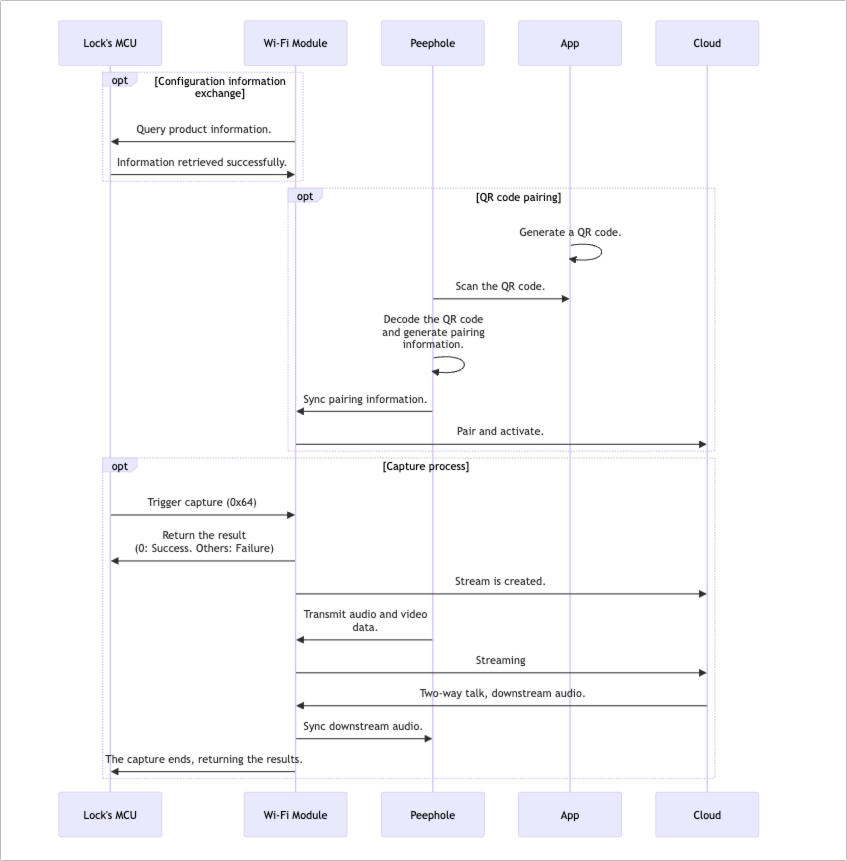
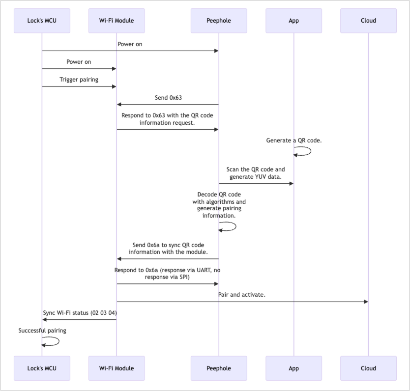
QR code pairing
How QR code pairing works:
Single UART for image upload
This is a low-cost image capture solution suitable for Wi-Fi modules without an SPI interface. The peephole is connected to the lock’s MCU, which controls image capture. The Wi-Fi module uploads images to the cloud.
Single SPI for image upload
This solution supports only image uploads. The Wi-Fi module communicates with the lock’s MCU via UART and connects to the peephole through SPI.
Before transmission, the peephole checks media upload readiness using the command 0x63. When the module returns Ready (0x02), the peephole transmits data in packets using 0x61. The peephole checks if the module is ready for the next packet via 0x67. It can only send the next packet once the module is ready. Repeat this process until all image data is uploaded.
SPI + single I/O for streaming
This solution enables peepholes without UART to upload images or videos.
- The lock’s MCU manages the power for both the Wi-Fi module and the peephole.
- If the capture type is an image, the peephole either waits for readiness for the next packet through
notify_ioor requests it via0x67. - For video and audio uploads, the peephole should wait for readiness for the next packet through
notify_io. - During audio and video uploads, the peephole stays powered on after activation. The peephole can either wait for the sleep command from the lock’s MCU or automatically enter sleep mode after 120 seconds, depending on power consumption.
SPI + dual I/Os for streaming
This solution is suitable for peepholes with enough GPIO pins but no UART. The peephole’s SPI is used for audio and video uploads, while the GPIO pins wake up the peephole and signal the readiness for the next packet.
During video uploads, the peephole starts a 5-second timer after waking up. If no notification for the next data packet is received within that time, it will return to sleep and wait to be woken up.
SPI + UART + single I/O for two-way talk
This solution is suitable for two-way talk applications. The peephole’s SPI transmits audio and video data, while the UART initiates and ends data transmission, notifies when it’s ready for the next packet, and the GPIO wakes up the peephole. Utilizing multiple interfaces speeds up audio and video transmission. The peephole must support UART for two-way audio talk. Otherwise, it cannot receive audio data from the app.
The SPI bus enables full-duplex communication, allowing image uploads while receiving audio data. When the peephole receives the command 0x69, it checks if the length of command 0x68 exceeds that of command 0x61. If the length of 0x68 is longer, pad the payload for 0x61 with zeros.
Appendix 1: Event capture code
| Event type | Code | Event type | Code |
|---|---|---|---|
| Anti-pry alert | 0x0000 | Remote unlocking request | 0x0001 |
| Fingerprint attempt | 0x0002 | Password attempt | 0x0003 |
| Card attempt | 0x0004 | Face attempt | 0x0005 |
| Palm print attempt | 0x0006 | Finger vein attempt | 0x0007 |
| Unlock with fingerprint | 0x0008 | Unlock with password | 0x0009 |
| Unlock with card | 0x000A | Unlock with face recognition | 0x000B |
| Unlock with palm vein | 0x000C | Unlock with finger vein | 0x000D |
| Unlock with temporary password | 0x000E | Unlock with dynamic password | 0x000F |
| Remote unlocking | 0x0010 | Report offline password unlocking | 0x0011 |
| Report doorbell request | 0x0012 | Duress alarm | 0x0013 |
| Low battery warning | 0x0014 | Mechanical key attempt | 0x0015 |
| High temperature | 0x0016 | Doorbell ringing and remote unlocking | 0x0017 |
| Loitering alert | 0x0018 | Lock tampering | 0x0019 |
| Unlock with special fingerprint | 0x001A | Unlock in arm mode | 0x001B |
| Unlock with a remote | 0x001C | Unlock with iris | 0x001D |
| Unlock with mechanical key | 0x001E | - | - |
Is this page helpful?
YesFeedbackIs this page helpful?
YesFeedback


