BK7231T COB Hardware Design Guideline
Last Updated on : 2024-06-24 06:01:48download
This topic describes hardware design guidelines on development based on the BK7231T Wi-Fi chip.
Application scope
BK7231T is a highly integrated wireless and radio frequency (RF) chip, with a built-in Wi-Fi protocol stack and various library functions. It features a low-power 32-bit CPU, 1T1R WLAN, 256 kbit static RAM, 2 MB flash, and various peripherals. As a real-time operating system (RTOS), BT7231T integrates all Wi-Fi MAC and TCP/IP libraries. You can develop your own embedded Wi-Fi products.
Features
- Built-in low-power 32-bit CPU, 256 kbit static RAM, and 2 MB flash.
- The maximum clock speed is 120 MHz.
- Full functionality of IEEE 802.11b/g/n Wi-Fi connectivity.
- Integrated Bluetooth Low Energy (LE) system.
- The maximum output power is +17 dBm for 802.11b transmission.
- Various peripheral interfaces include PWM, I2C, UART, SPI, SDIO, USB, and IrDA.
- Operating voltage: 3.0V–3.6V
- Operating temperature: -40°C–105°C
Minimal system diagram
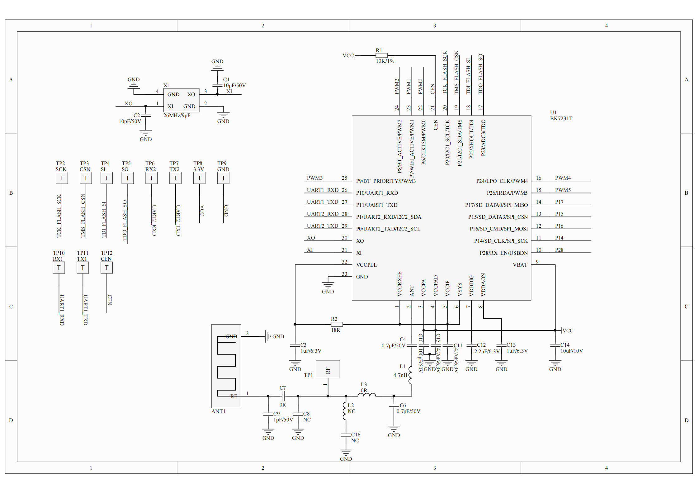
Circuit design
RF power
| Communications | Wi-Fi standard | Rate | Transmitted/received power | Typical value | Unit |
|---|---|---|---|---|---|
| Transmit | 802.11b | 11 Mbit/s | +17 dBm | 220 | mA |
| Transmit | 802.11g | 54 Mbit/s | +14 dBm | 200 | mA |
| Receive | 802.11g | 54 Mbit/s | -10 dBm | 104 | mA |
| Receive | 802.11n | MCS 7 | -10 dBm | 124 | mA |
Note: It is recommended to select a power supply with a steady-state power of ≥ 3.3V/220 mA and the peak current limit of ≥ 400 mA.
RF design
- Test point
To facilitate flashing firmware and functional testing in the production test, in chip on board (COB) design, I/O pins for testing need to be broken out to pads. Prepare 11 test points including serial port pins, power-supply pins, reset pin, and SPI flash pins as well as one RF test point.
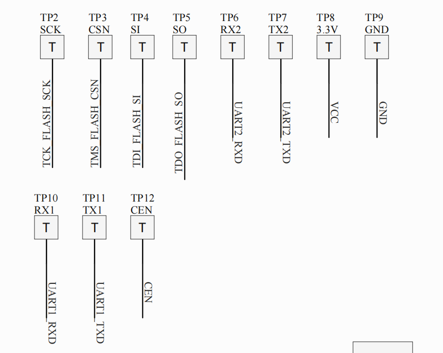
- RF test point (RF_PAD)
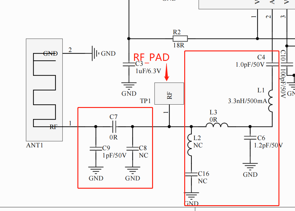
The following circuit diagram shows the RF link on the chip for on-board design. To perform RF calibration, place an RF_PAD between the antenna matching link (C7, C8, and C9) and chip filter circuit (C4, L1, C6, L3, and L2). RF_PAD is required.
Disconnect the antenna matching link to calibrate RF on the chip. Disconnect the chip filter circuit to calibrate RF on the antenna.Note:
- The parameters of the matching link and the filter circuit must be obtained by testing your actually used board. The parameters shown in the figure do not apply to the board after re-layout.
- The test points and RF_PAD cannot be tinned during production.
RF layout
-
To reduce the signal loss, the RF trace from the RF pin to the antenna should be as short as possible. The characteristic RF impedance must be 50 Ω. The components should be placed as compactly as possible but not too close. The minimum pad-to-pad spacing is 0.3 mm.
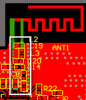
-
Provide two layouts for on-board PCB antennas.
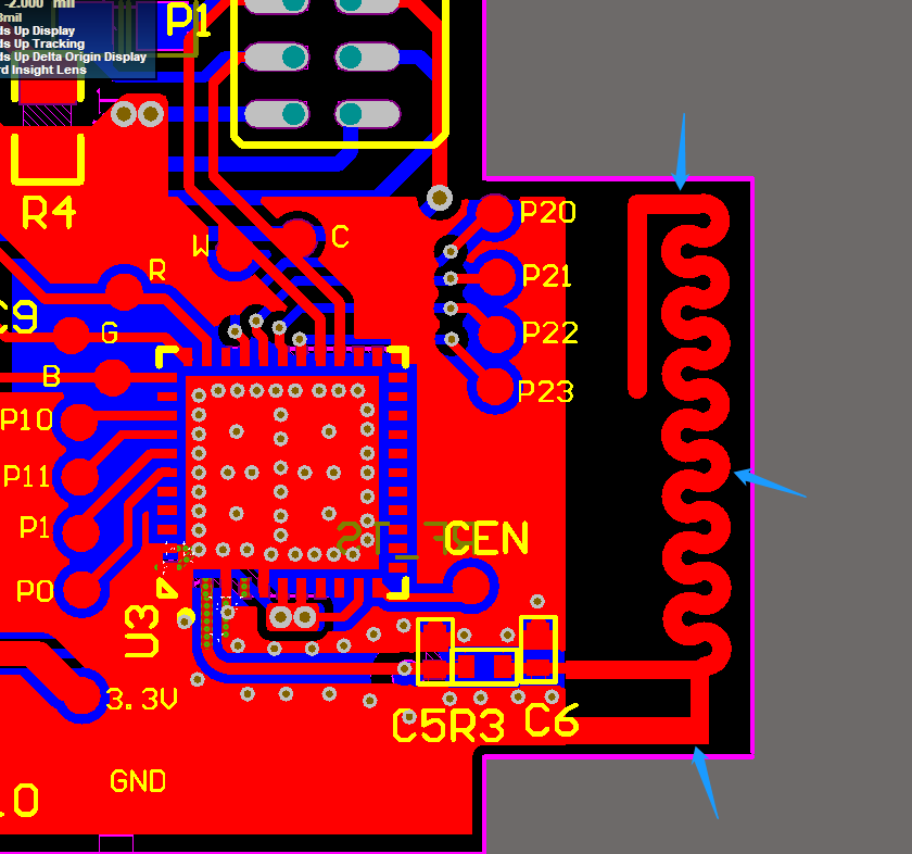
- Placed outside the edge of board: The distance between the antenna trace and the edge of the board must be greater than 12 mil. As shown below, the blue arrow indicates the width.
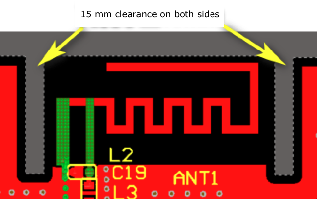
- Embedded into the board: The distance between the trace and the edge of board should be greater than 12 mil. Have a 15 mm clearance on both sides of the antenna. It is recommended not to place components on the clearance area. If the layout on the clearance area is required, copper pour and larger metal components are not allowed.
- Placed outside the edge of board: The distance between the antenna trace and the edge of the board must be greater than 12 mil. As shown below, the blue arrow indicates the width.
-
Trace and copper pour are not allowed on the antenna area of each layer.
-
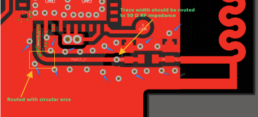
The trace width from the RF pin to the antenna RF feed point should be routed strictly to 50 Ω RF impedance. The trace width is related to the board thickness and the number of layers. You can refer to the design guideline provided by the PCB board manufacturer. The RF trace should be routed with circular arcs.
-
The ground plane on the adjacent layer must be complete, which must not be branched.
-
Trace must not be routed under the RF trace.
-
Place filter capacitors as close as possible to the pins. The ground pin of the capacitor directly passes through the via to the ground plane.
-
The surface of the chip and peripheral circuits and the adjacent layer should be filled with copper to create a ground plane.
-
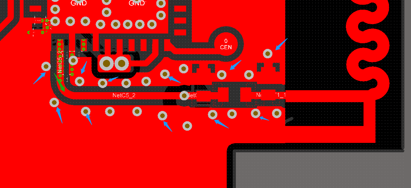
The RF trace should be surrounded by grounding copper. Anti-interference is achieved through symmetrical vias. The size of the via is 8 mil inner diameter and 16 mil outer diameter. Cover the gaps with ink.
-
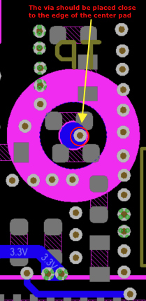
RF_PAD is placed on the bottom layer, between the chip and the antenna matching position. During crimp connection, to avoid damage to vias by the test probe, the vias should not be placed on the center of the pad but close to the edge of the center pad.
-
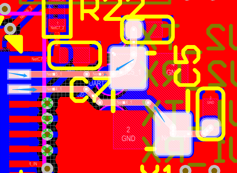
The trace of the crystal oscillator should be as short as possible. To prevent electromagnetic interference (EMI), add ground vias around the crystal oscillator.
-
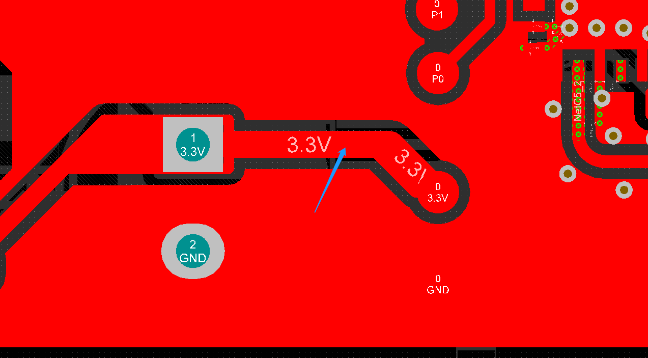
The width of the 3.3V power traces should be no less than 20 mil. There should be at least two vias where the power traces cross layers.
Antenna design
Select an antenna depending on the shape and space constraint of your product. The types of antennas include PCB antennas, electronic antennas, helical antennas, FPC antennas, and ceramic chip antennas.
Note: The area around the antenna should be kept clean.
Antenna matching circuit
The antenna matching circuit is shown below.
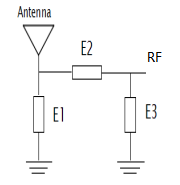
- The optimal value of the E2 capacitor varies depending on traces, boards, and the number of layers. The empirical value ranges from 1.8 nH to 4.7 nH, and the recommended value is 3.6 nH.
- Generally, you do not need to mount E1 and E3 capacitors directly onto the surface of the PCB. To achieve the best antenna performance with respect to the radiation efficiency and connection range, you need to perform debugging based on antenna designs.
Recommended PCB antenna
-
Shape A: Meandered inverted-F antenna is the most extensively used antenna.
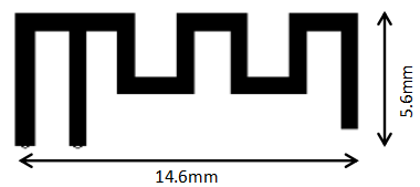
-
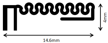
Shape B: The bends of a meandered inverted-F antenna are curved, which take less vertical space while retaining its designed trace length. This shape applies to lights that have height constraints to light panels.
-
Shape C: Vertical traces are lengthened, and horizontal traces are shortened. This shape applies to products that have horizontal space constraints but no vertical space constraints, such as strip light controllers.
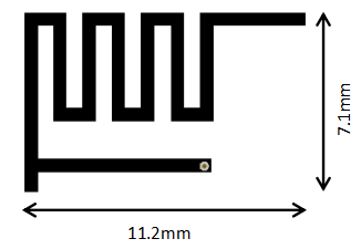
Note: You can request antenna assembly files from Tuya’s account managers.
Other recommended antenna types
-
If pads or vias are reserved on the board, electronic antennas or helical antennas are recommended.

-
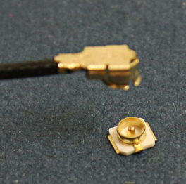
If IPEX antenna mounts are reserved on the board, FPC antennas and external antennas are recommended.
Flash firmware and authorize module
Preparation
- A USB to SPI adapter board that has a writer and USB cable. The writer provides two SPI interfaces, SW SPI and HW SPI, corresponding to two flashing methods.
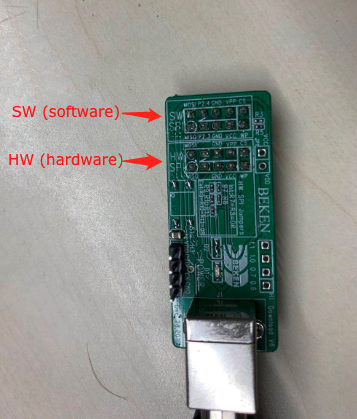
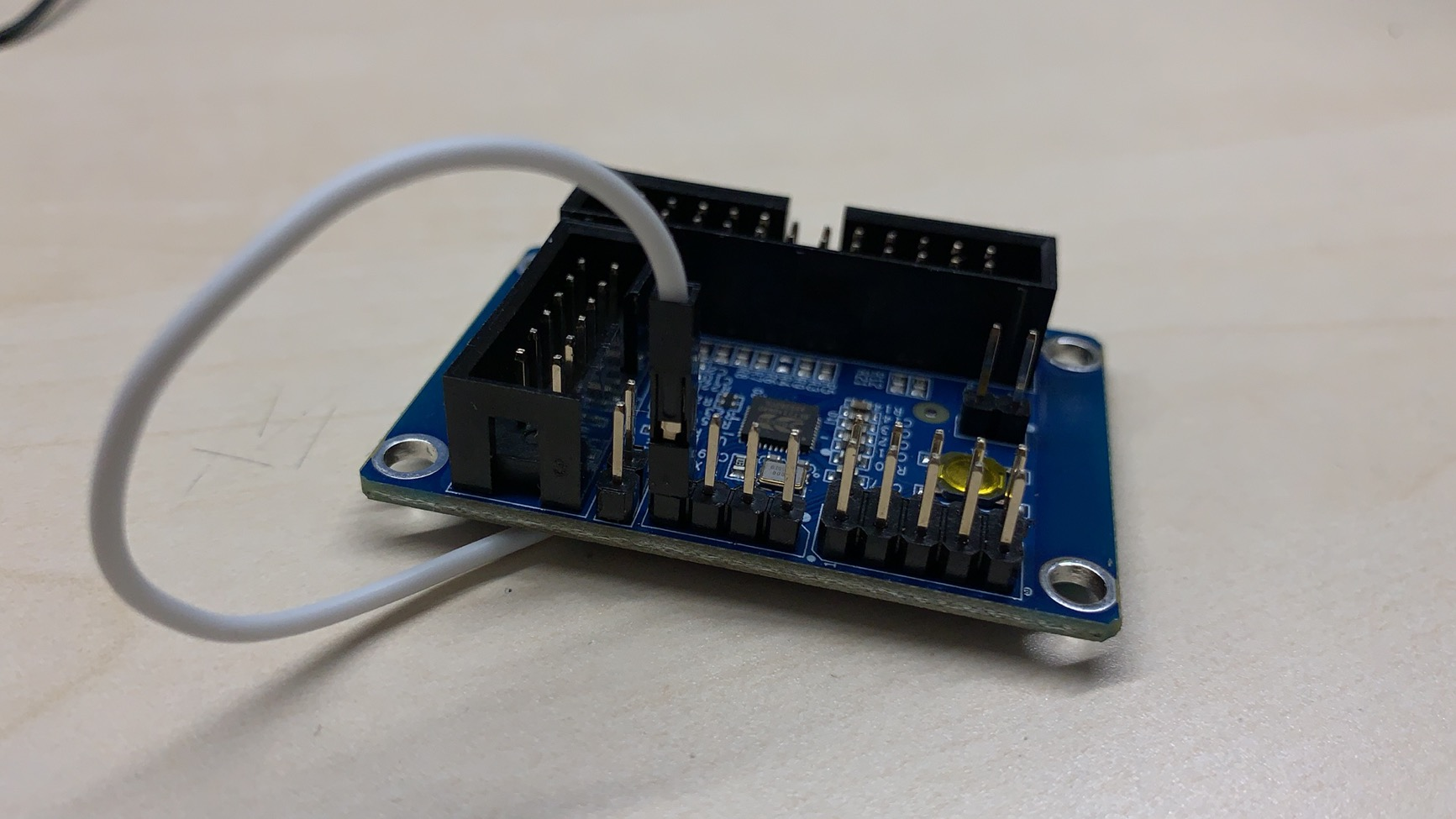
- Use a backplane for SPI flashing, as shown below.
Procedure
-
Flash the boot firmware to the backplane.
-
Insert the USB-SPI board into the backplane in the correct direction, as shown below. Make sure the correct SPI interface is inserted.
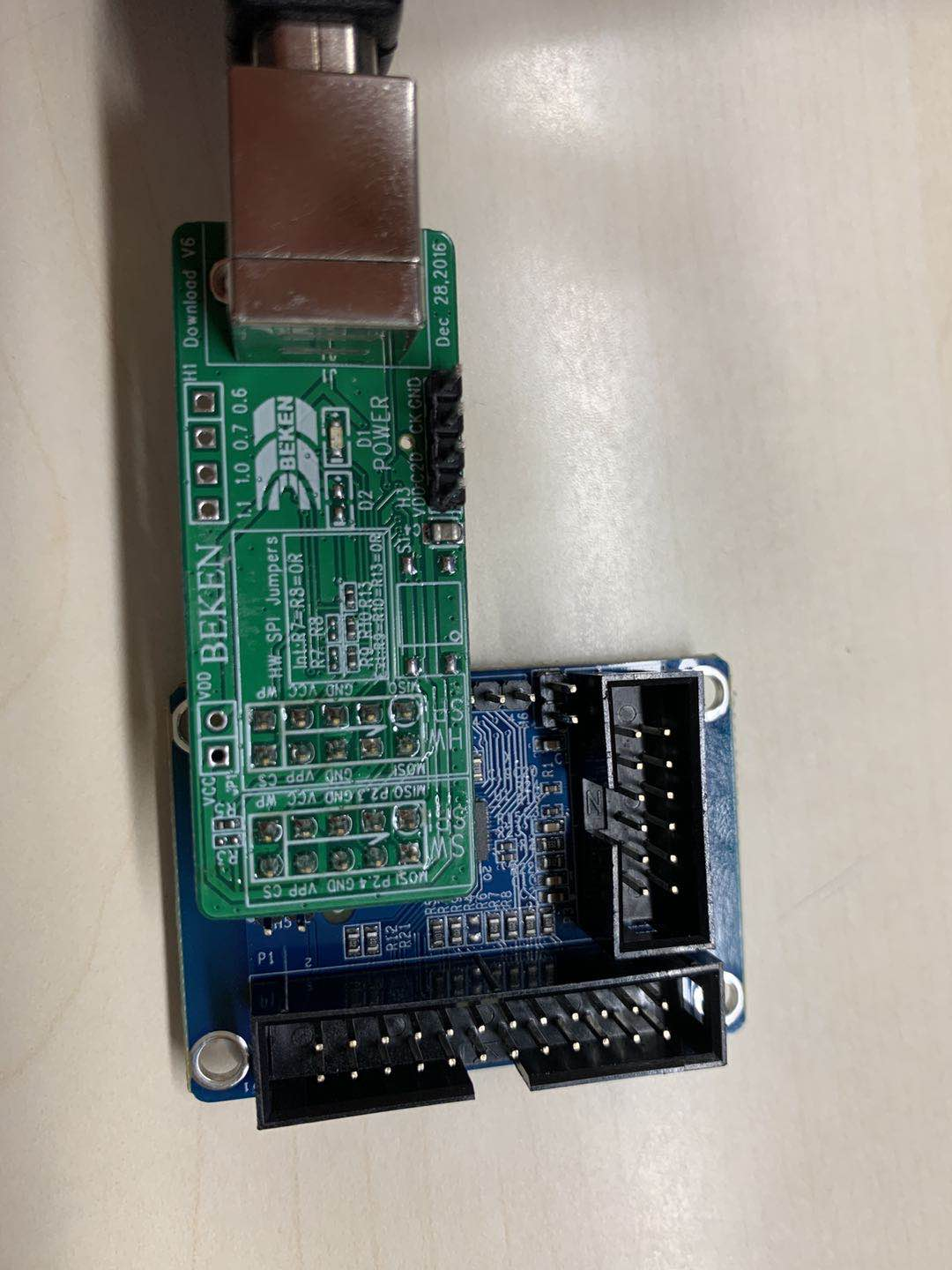
-
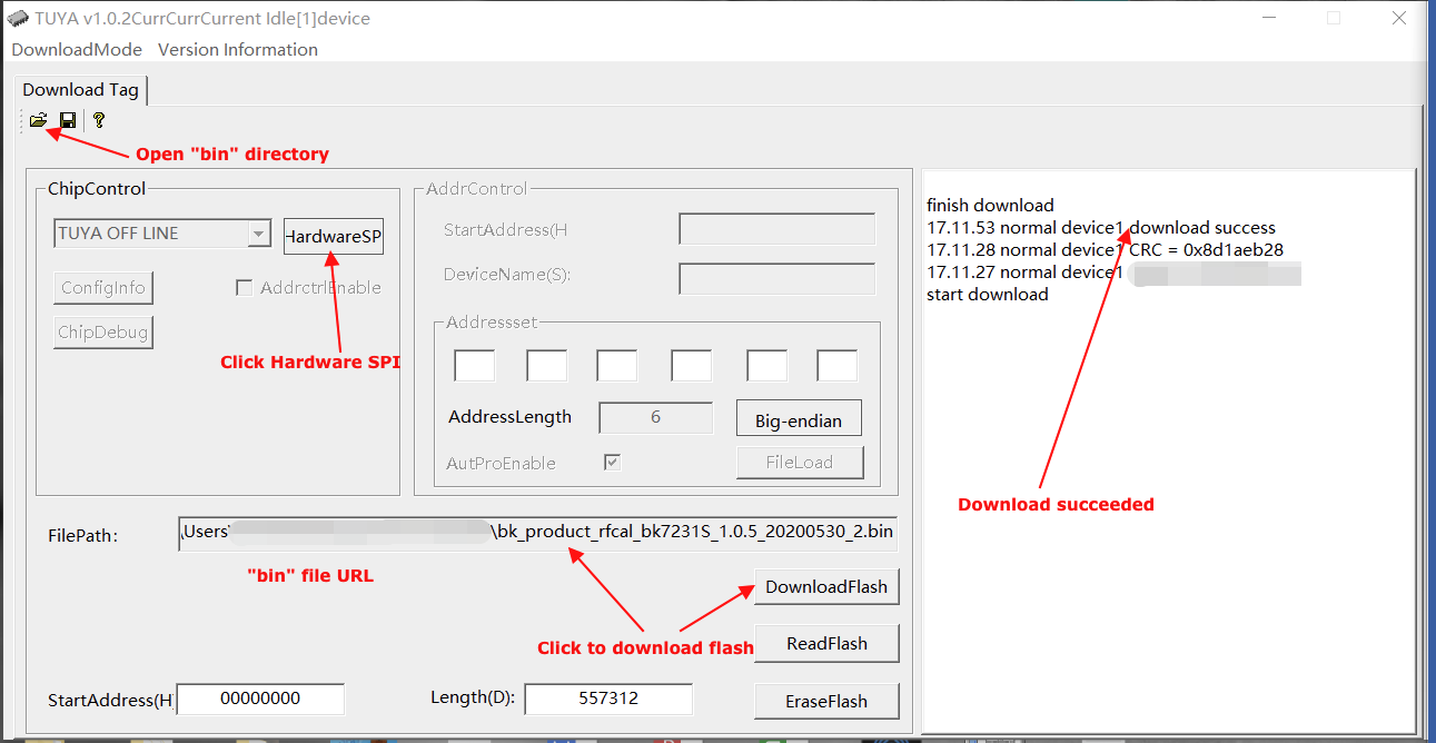
Open the binary file
bk_product_rfcal_bk7231s_1.0.5_20200530_2.binin MXCHIP, select the SPI type, and click Download.
After the download starts, the progress will be displayed on the right side of the software interface.
-
-
Flash the boot firmware on the backplane to the chip.
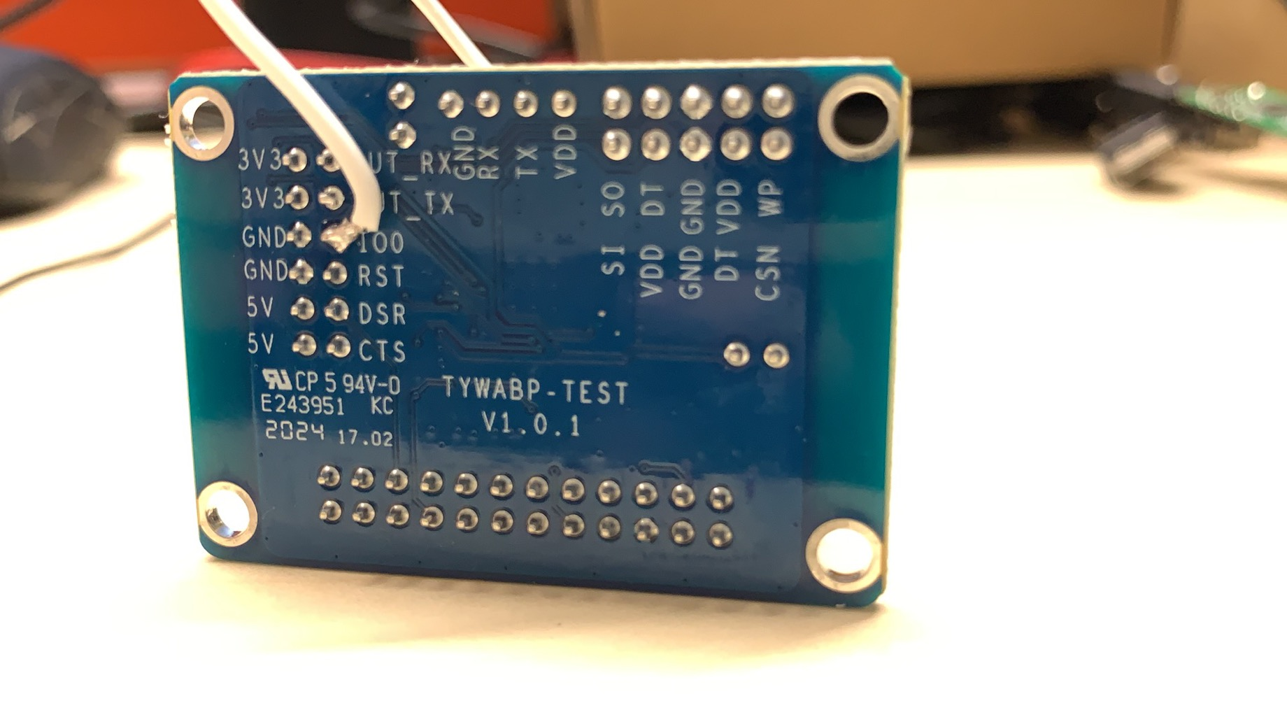
- Flash the boot firmware on the backplane to the module by grounding the I/O0 lead on the backplane.
- Connect the test jig to the PC. The PC is connected to the backplane through a serial-to-USB adapter and powers the backplane and test jig. The backplane has a group of electrical connectors and two indicator signal cables connected to the test jib. The indicator has red and green LEDs. The color displayed in each test might be inconsistent due to the cable mapping, which does not affect the test.
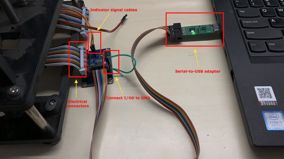
The indicator on the test jig has three states:- State 1: When the test jig is idle, you can press down the toggle clamp. If one indicator is on and the other flickers at regular intervals, it indicates the test jig works properly.
- State 2: When a module is inserted to the jig, you can press down the toggle clap. If the two indicators are on steady, it indicates the firmware on the backplane is being flashed to the module.
- State 3: After flashing is completed, one indicator is off steady and the other is on steady.
- Flash the boot firmware on the backplane to the module by grounding the I/O0 lead on the backplane.
-
Flash application firmware and authorize module
-
Connect the test jig in the same manner as step 2 above but disconnect the I/O0 to GND of the backplane. Then, you can start flashing and authorization.
-
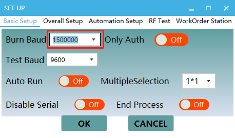
Open the software Cloud Module Burning Authorization Platform. Click File > Set Up and set Burn Baud to
150000and Test Baud to9600.
-
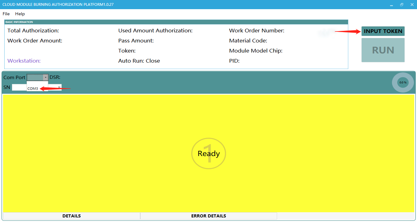
Select the COM port for the connected serial-to-USB adapter. Click Input Token.
-
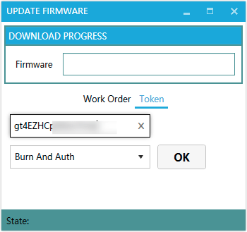
On the Update Firmware dialog box, click Token to enter the authorization code of BK7231T. Select Burn And Auth from the dropdown list and click OK.
-
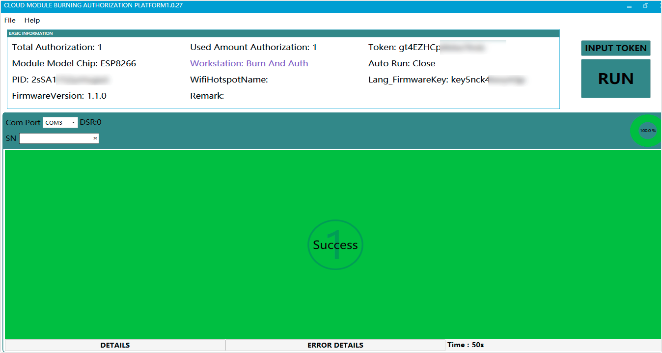
Click Run. When authorization and flashing are completed, the interface shows Success.
-
Note:
- After the boot firmware is flashed, you can start to test and calibrate the RF performance of BK7231T. Because flashing application firmware will overwrite boot firmware, you should flash boot firmware again in case of testing again.
- The development board and test jig production instructions used in the firmware flashing and activation process can be submitted to Tuya BD for requirements. You can request the documents of the development board and test jig from Tuya’s account managers.
- If you use the self-calibration circuitry integrated on BK7231T, apply a 10K ohm resistor from the P28 pin to GND.
BK7231T self-calibration circuitry
The featured self-calibration circuitry integrated on BK7231T modules addresses the needs of calibration without external fixtures and reduces costs.
Precision comparison
- For chips calibrated by the WT-208 or WT-200 tester from iTest Technology, the accuracy of transmitter power output is ±1 dB.
- Accuracy registered by self-calibration circuitry is generally ±2 dB to 3 dB. The self-calibration is performed at the moment the device is powered on, which is impacted by RF link and antenna matching. The better the matching, the higher the self-calibration accuracy can be reached.
Things to note
- Hardware design: If you use the self-calibration circuitry integrated on a cob-assembled PCB, apply a 10K ohm resistor from the P28 pin to GND.
- Firmware design: Specific application firmware is used for self-calibration. Calibration runs the boot firmware of the same version as that on the backplane.
Is this page helpful?
YesFeedbackIs this page helpful?
YesFeedback


