Product Hardware Design Considerations
Module power supply circuit:
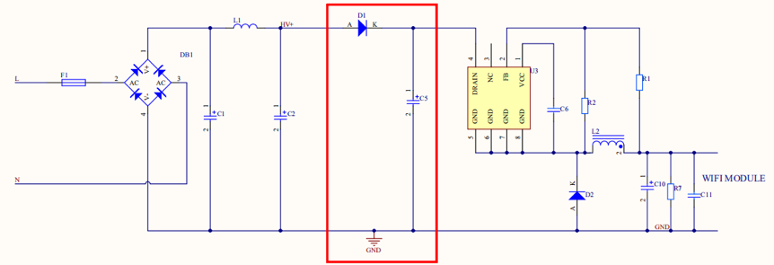
AC-DC constant voltage output
Normal range of module operating voltage of: 3.0 to 3.6V.
- If the output voltage is higher than 3.3V, the output voltage ripple and output power other than the supply module should be considered. Prevent insufficient output power to cause output voltage undervoltage. Prevent insufficient output power to cause insufficient power supply. You must ensure that the module’s power supply voltage is stable under the maximum output power.
- If the output voltage is the module power supply voltage of 3.3V, set the center value of the output voltage to 3.3V, the output voltage ripple to less than 100 mV, the average current of WiFi is about 80mA. Ensure the ACDC can output the current at the average voltage of 200 mA. The power output dynamic current needs to reach a peak value of 450mA. The voltage drop should not exceed 2.8V. Filter out the interference of the 3.3V WIFI module power supply pin and the 0.1 uF tile capacitor. For Bluetooth and Zigbee power supply, the output voltage ripple of 3.3V should be less than 100mV. Ensure the DC/DC can output the current at the average voltage of 50 mA. When the output current is 100mA under dynamic conditions, the output voltage drop does not exceed 2.8V.
In the application of low standby power consumption, you should select ACDC of low standby power consumption. You should also apply the module of low standby current.
A diode and a capacitor must be used to separate the AC-DC power supply circuit from the LED driver. This can minimize the impact on the primary power supply and ensure module performance. Particularly, for the linear constant-current power supply, this isolation mechanism can be used to avoid light flickering.
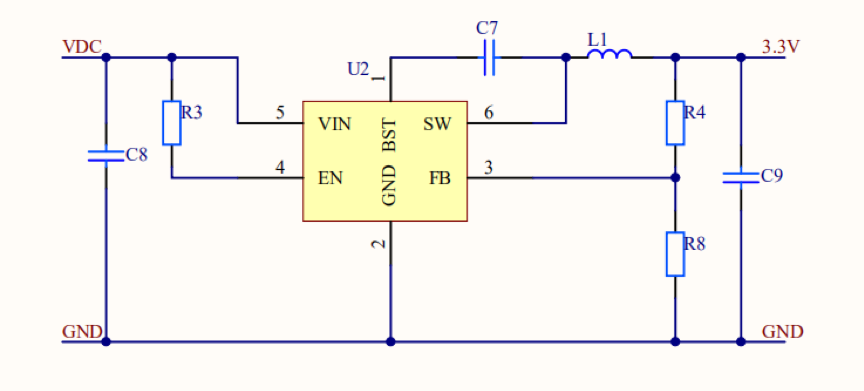
DC-DC constant voltage output
- If the DC voltage is supplied to a module with a built-in DC/DC step-down circuit, the DC voltage cannot exceed 40V.
- If the DC voltage outputs a voltage of higher than 3.3V, we recommend that you step down the voltage to 3.3V. Recommend you to control the chip with switch step-down. It is shown as follows. When using the WIFI module, make sure the output voltage ripple of 3.3V is less than 100mV, and the DC/DC can output a 200mA current. When the output current is 450mA under dynamic conditions, the output voltage drop does not exceed 2.8V. Add a 0.1uF ceramic capacitor close to the power supply pin of the 3.3V WiFi module to filter out interference. For Bluetooth and Zigbee power supply, the output voltage ripple of 3.3V should be less than 100mV. Ensure the DC/DC can output the current at the average voltage of 50 mA. When the output current is 100mA under dynamic conditions, the output voltage drop does not exceed 2.8V.
We recommend that you do not use an LDO regulator in the power supply for a Wi-Fi module. For example, if an LDO is used, the power supply current of the IC must be 500 mA or higher. The heat dissipation performance must meet your business requirements. We recommend you use the switch power chip when the input voltage is higher than 5V.
LED driver circuit
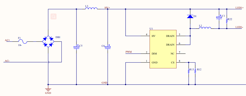
One-channel dimming for a W-AC/DC constant current driver
Switch type dimming for an AC/DC constant current driver. It is shown as follows.
- Benefits: high efficiency, excellent constant current performance, and linearity. and a wide adjustable range of output voltage.
- Disadvantages: poor anti-electromagnetic interference (EMI) performance, high costs, noisy PWM dimming signals, and a complex printed circuit board (PCB) layout.
In this solution, the module outputs PWM signals.
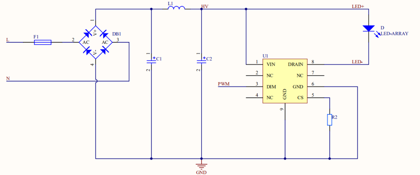
Linear dimming for an AC-DC constant current driver
-
Benefits: low costs, free of EMI issues, a simple PCB layout, and noise-free PWM dimming.
-
Disadvantages: low efficiency, poor constant current performance in a narrow voltage range, unexpected linearity, fixed output voltage, and low PFs.
In this solution, the module outputs PWM signals.
Two-channel dimming for an AC/DC constant current driver
The two-channel dimming solution supports the following control methods: cool and warm (CW) white light control and correlated color temperature (CCT) control.
CW white light control is implemented by two channels of PWM signals. Each channel is used for mixed control of brightness and color temperature.
Two-channel: CW and WW.
- The cool-white (CW) channel controls white light (high color temperature). The warm-white (WW) channel controls warm light (low color temperature). The CW channel is used for single-channel dimming.
- For the CCT control method, brightness control is separated from color temperature control based on two signal channels. One channel controls brightness and the other channel controls color temperature. For details, see Pin out.
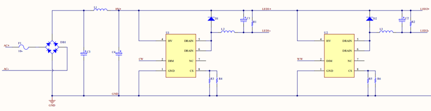
Switching power supply with CW control (on and off)
-
Benefits: high efficiency, excellent constant current performance, linearity, expected dimming effect,
-
Disadvantages: poor anti-EMI performance, noisy circuits, large color temperature shift for a small duty cycle, a complex circuit layout, and high costs.
In this solution, the module outputs two channels of PWM signals: CW control and WW control.
CW control (linear)
-
Benefits: low costs, free of EMI issues, a simple PCB layout, and noise-free PWM dimming.
-
Disadvantages: low efficiency, poor constant current performance in a narrow voltage range, unexpected linearity, fixed output voltage, and large color temperature shift for a small duty cycle.
In this solution, the module outputs two channels of PWM signals: CW control and WW control.
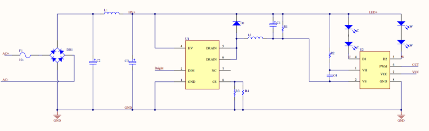
CCT control
-
Benefits: high efficiency, excellent constant current performance, linearity, expected dimming effect, noise-free analog brightness control, a simple circuit layout, and low costs.
-
Disadvantages: poor anti-EMI performance, little color temperature shift, and higher costs than linear CW control.
In this solution, the module outputs two channels of PWM signals: brightness control and CCT control.
Dimming for a constant-current RGB driver
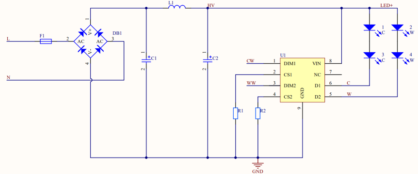
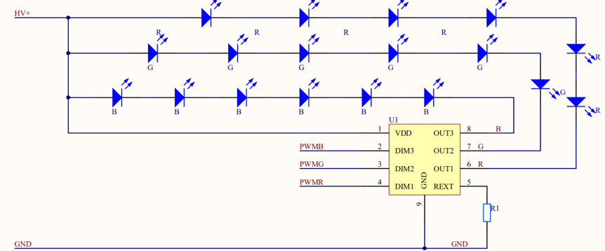
DC/DC linear constant-current driver with PWM control
In this solution, the module outputs three channels of PWM signals: PWMR, PWMG, and PWMB. The linear constant-current driver can enable constant output of red, green, blue (RGB) current.
DC/DC linear constant current drive with IIC control
In this solution, Inter-Integrated Circuit (IIC) control requires the data (DAT) and clock (CLK) pins to control three-channel or five-channel LEDs.
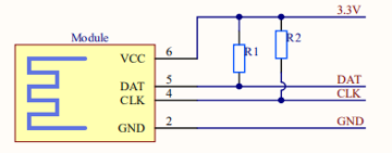
Few control pins are used in this solution to minimize the load of module pins, which reduces the burden on the module pins. The module outputs DAT and CLK IIC signals to the driver IC to control the RGB constant current. In this solution, PCB layout traces must be optimized. IIC signals are susceptible to interference from switching signals that are sent by the ACDC driver circuit. To minimize the interference, we recommend that you connect filter capacitors (10 pF to 50 pF) with the DAT and CLK pins to filter signals in the PCB layout.
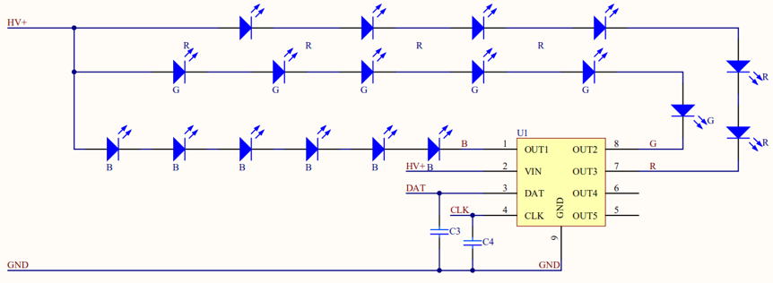
Pull-up resistors must be added to the peripheral DAT and CLK signals of the module when IIC signals are processed. The resistance is recommended to be 4.7 kΩ and can be modified based on the application requirements.
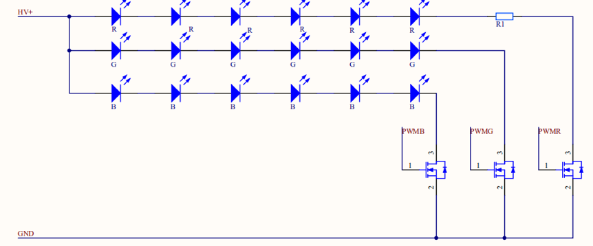
DC-DC BJT or MOS switching driver with PWM control
In this solution, a bipolar junction transistor (BJT) or a MOS transistor is used to transmit PWM switching signals and control RGB LEDs. RGB is not constant current. In the same input conditions, a low voltage is applied to red LEDs. Therefore, a resistor is added to the red LED trace to limit current. However, this increases unnecessary power consumption. A low voltage dropout is applied between the lamp bead voltage and the input voltage.
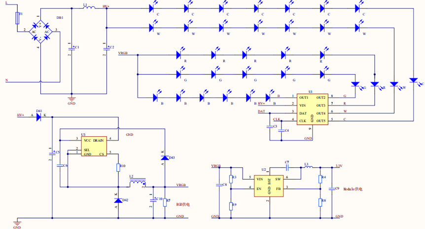
Five-channel dimming for an AC/DC IIC linear constant current driver
-
Benefits: a simple layout, simple peripheral parameters, low costs, and easy control of only DAT and CLK signals.
-
Disadvantages: DAT and CLK signals are vulnerable to interference from the linear constant-current driver.
In this solution, RGB lights are powered separately from the CW white lights. We recommend that you use both the AC-DC and DC-DC solutions to power the module.
Others
When Espressif’s 8266 chip is connected to the power, and some IOs are unstable and initialized to output weakly, there will be a high pulse (for 180ms). So the high-level light may flash. In order to avoid this situation, these IOs can be connected to an external pull-down resistor with a resistance value less than 3.3K.
Is this page helpful?
YesFeedbackIs this page helpful?
YesFeedback


