Production Notes and Troubleshooting
Last Updated on : 2024-06-21 04:01:54download
Production assembly stage:
The most common problem is module breakdown. Inadequate factory electrostatic protection and improper operation by workers may cause module failure. Therefore, it is important to make sure that the process is standardized. Now we can have an analysis of the production procedure.
Inspection of received itemscheck whether the module is normal before production
- The simple judgment method is to adjust the multimeter to the diode buzzer file and measure the value between the VCC and GND pins of the module. The measured values of different modules are not the same, and the standards cannot be unified. Please compare with the measured values of the normal module during operation to determine whether the module is invalid.
- In mass production, tooling should be used to inspect the incoming materials of the module. This process can detect the quality of the module and view information such as product PID and SN code.
Attached SMT: In this process, you should make sure
- that the attached device is connected to the ground.
- The furnace temperature setting must conform to the temperature curve to avoid internal chip offset and tin connection problems in the module.
- When the driver board is transferred, be wary of the static.
Manual plugin
-
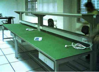
Ensure effective grounding of the console and the device, and regular maintenance to avoid poor grounding.
Note: You are required to use electrostatic skin instead of insulating skin for the console. The impedance is different between the two materials. The electrostatic skin contains conductive material and has lower impedance than the insulating skin.
-
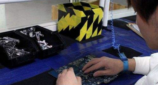
Workers need to wear a wire electrostatic ring and try not to touch the module with their hands during the plug-in process.
The temperature of the wave soldering furnace must conform to the temperature curve to avoid internal chip offset and tin connection problems in the module.Note: The furnace temperature curve of different modules is different, please operate according to the recommended furnace temperature curve on the module datasheet.
-
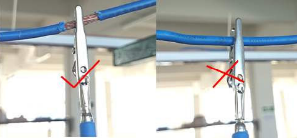
When the wave soldering is finished manually, the soldering iron should be grounded.
Drive power-on test
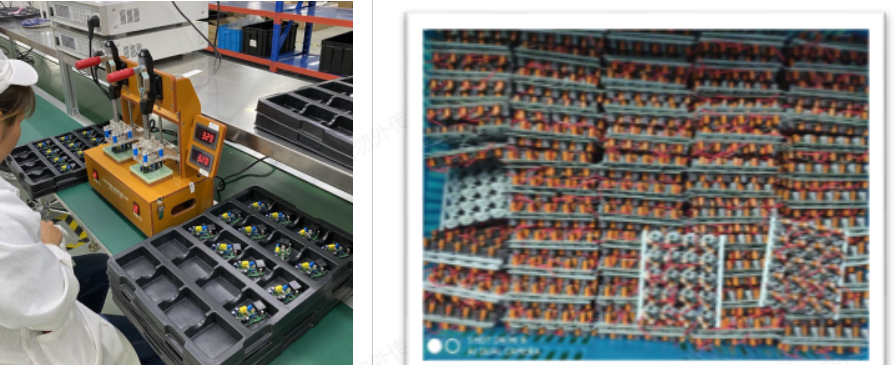
- Please use the test tool to power on the driver. Some factories will directly connect the AC line to the power board for testing, and sparking occurs when contacting. This has certain hidden dangers to the safety of the module.
- The drive test tooling is maintained regularly to avoid the problem that the light does not turn on due to poor connector contact and misjudgment by workers.
- When passing the conveyor belt and placing it after power-on, the drivers should be separated separately to prevent secondary damage to the module caused by residual power.
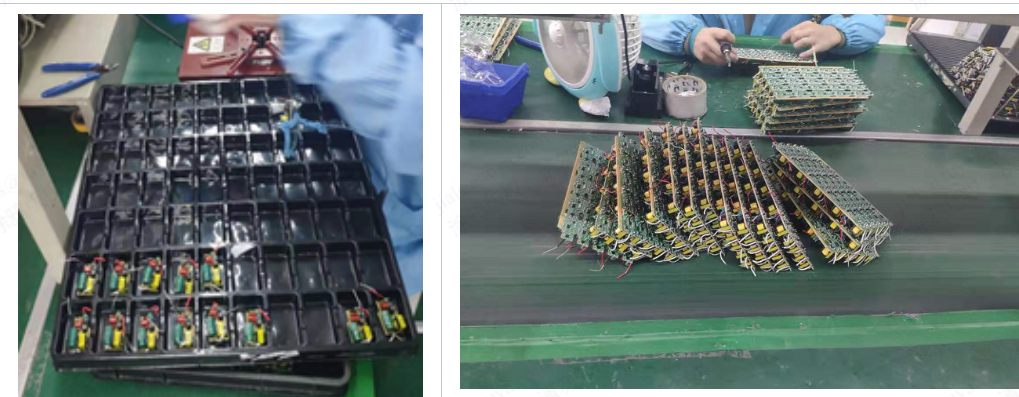
Whole lamp assembly
The whole lamp is separately separated when powered on
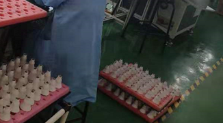
Defective product repair
- Criteria for judging module failure: The test is the same as the incoming material detection part of the procedure. If you are not sure, contact the relevant personnel of Tuya
- To avoid confusion, the maintenance staff are recommended to be the same.
- Data recording: Record every link where the bad module problem occurs, and count the failure ratio to locate the problem.
Is this page helpful?
YesFeedbackIs this page helpful?
YesFeedback

