Function Definition
After a product is created, define its functions first.
You can set functions for a product, including standard functions, custom functions, and advanced functions. This topic describes typical function definitions of smart metering sockets.
Standard function definition
DP list of standard functions
| DP ID | DP | Identifier | Data transfer type | DP type | DP property | Required |
|---|---|---|---|---|---|---|
| 1 | Power 1 | switch_1 | Send and report | bool |
|
Yes |
| 9 | Countdown of switch 1 | countdown_1 | Send and report | value |
|
Yes |
| 17 | Added electricity | add_ele | Send and report | value |
|
Yes |
| 18 | Current now | cur_current | Report only | value |
|
Yes |
| 19 | Power now | cur_power | Report only | value |
|
Yes |
| 20 | Voltage now | cur_voltage | Report only | value |
|
Yes |
| 21 | Test bit | test_bit | Report only | value |
|
Yes |
| 22 | Voltage COE | voltage_coe | Report only | value |
|
Yes |
| 23 | Electric COE | electric_coe | Report only | value |
|
Yes |
| 24 | Power COE | power_coe | Report only | value |
|
Yes |
| 25 | Electricity COE | electricity_coe | Report only | value |
|
Yes |
| 26 | Error | fault | Report only | fault | Valid values: ov_cr, ov_vol, ov_pwr, ls_cr, ls_vol, and ls_pow. |
Yes |
| 38 | Restart status | relay_status | Send and report | enum | Enumeration values: off, on, and memory. |
Optional |
| 41 | Cycle timing | cycle_time | Send and report | string | See the protocol in function description. | Optional |
| 42 | Random timing | random_time | Send and report | string | See the protocol in function description. | Optional |
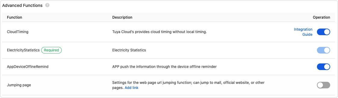
Advanced functions
With Cloud Timing enabled, you can set recurring tasks from Monday to Sunday to regularly switch on or off a device. The scheduled tasks support automatic adjustment for daylight saving time (DST).
Function description
Energy metering
-
Added electricity: reports incremental power consumption of the device.
-
Current now, voltage now, and power now: real-time parameters of the device. If a certain threshold is exceeded, actual values are reported to improve data accuracy.
-
Power coe, electric coe, and electricity coe: calibrates metering data.
-
Error: reports various fault values such as overcurrent, overvoltage, overpower, and undervoltage.
Bitmap Fault value Bit0 ov_cr Bit1 ov_vol Bit2 ov_pwr Bit3 ls_cr Bit4 ls_vol Bit5 ls_pow
Advanced timing
-
Cycle timing: You can set up to 10 cycle timing tasks. Every 10 bytes are described as follows:
- Byte 1: indicates the channel ID.
Bit 0: switch.Bit 7tobit 1: channel ID. - Byte 2: indicates the week.
00: only once,01: Sunday,02: Monday,04: Tuesday,08: Wednesday,10: Thursday,20: Friday, and40: Saturday. - Bytes 3 and 4: indicates the start time. Unit: in minutes.
- Bytes 5 and 6: indicates the end time. Unit: in minutes.
- Bytes 7 and 8: indicates the enabling time. Unit: in minutes.
- Bytes 9 and 10: indicates the disabling time. Unit: in minutes.
- Byte 1: indicates the channel ID.
-
Random timing: You can set up to 16 random timing tasks. Every 6 bytes are described as follows:
- Byte 1: indicates the channel ID.
Bit 0: switch.Bit 7tobit 1: channel ID. A power strip has 0 to 6 outlets. - Byte 2: indicates the week.
- Bytes 3 and 4: indicates the start time. Unit: in minutes.
- Bytes 5 and 6: indicates the end time. Unit: in minutes.
- Byte 1: indicates the channel ID.
Restart status
Enumeration values of power status setting are described as follows:
-
none: The indicator light is steady off. This value is recommended for use at night, ensuring a good sleep for users. -
relay: The indicator light denotes the switch status. The indicator light is on when the switch is on, and the indicator light is off when the switch is off. -
pos: The indicator light denotes the position of the device. The indicator light is off when the switch is on, and the indicator light is on when the switch is off. This value is recommended for use at night, so as to help users quickly locate the socket. It is similar to the function of the fluorescent strip in a traditional socket.
Power status setting only applies to power indicator lights for I/O control or indicator lights that are reused as a power indicator light.
Is this page helpful?
YesFeedbackIs this page helpful?
YesFeedback


