Troubleshoot Smart Metering Socket
This topic describes how to troubleshoot common problems that can occur when you develop a smart metering socket.
Troubleshooting procedure
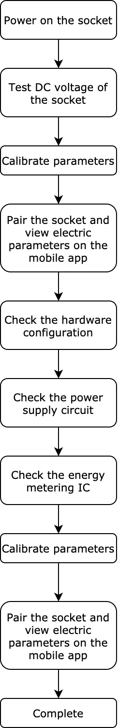
Troubleshooting steps
Test DC voltage of the socket
-
Use an oscilloscope to test the DC voltage of the socket.
-
Read voltage waveforms on the oscilloscope and determine whether the result is acceptable.
Metric Acceptable result 5V 4.6V to 5.5V 3.3V 3.0 to 3.6V For the socket and the oscilloscope, one of them must be driven by an isolated power supply.
Pair socket and check values
-
Connect the socket to the power supply without a load attached to it.
-
Press and hold the reset button to enter pairing mode. The LED flickers quickly in EZ mode and slowly in AP mode.
-
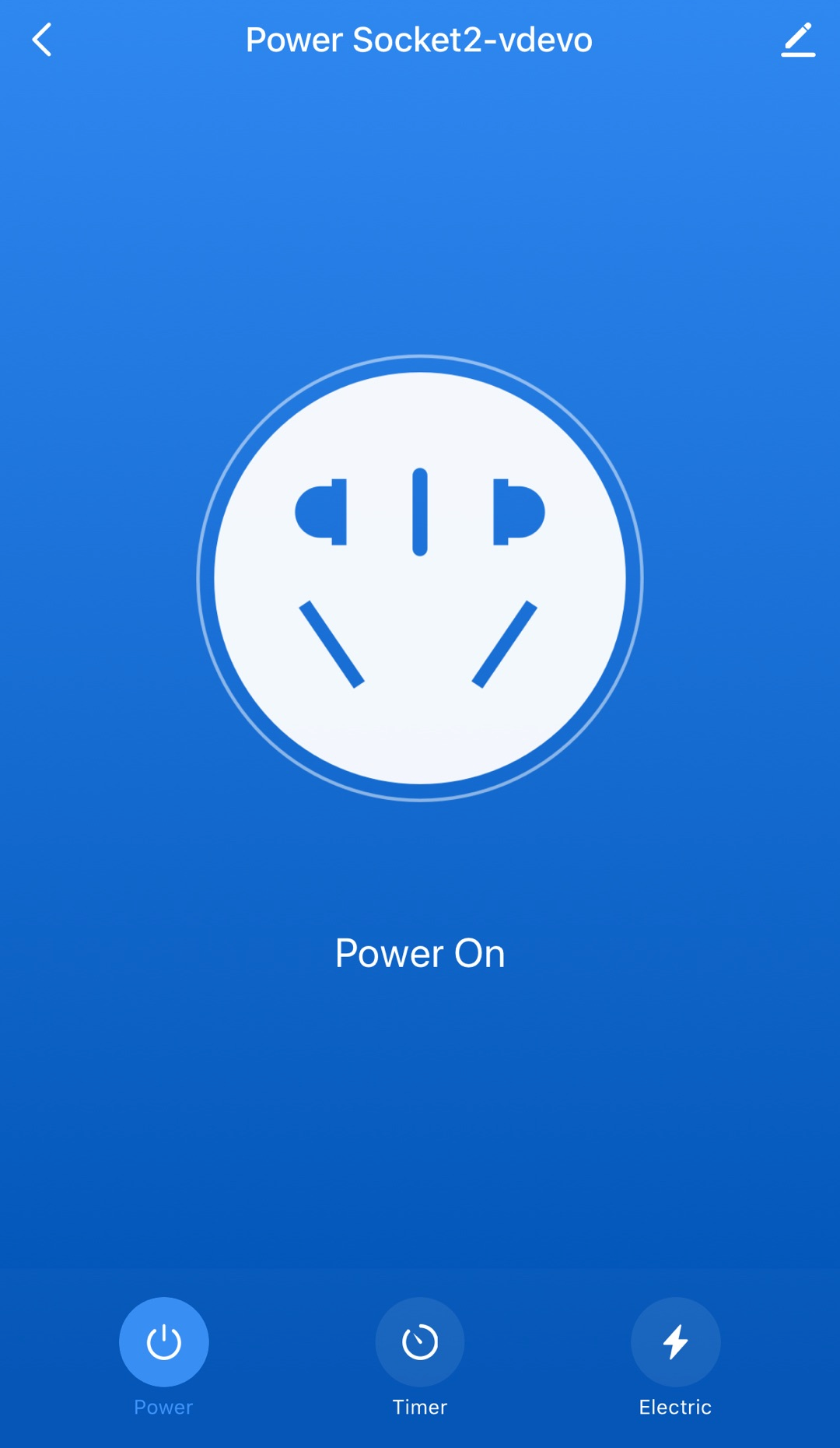
Open the Tuya app and pair it with the socket.
-
This socket will be displayed in the device list on the homepage after successful pairing.
-
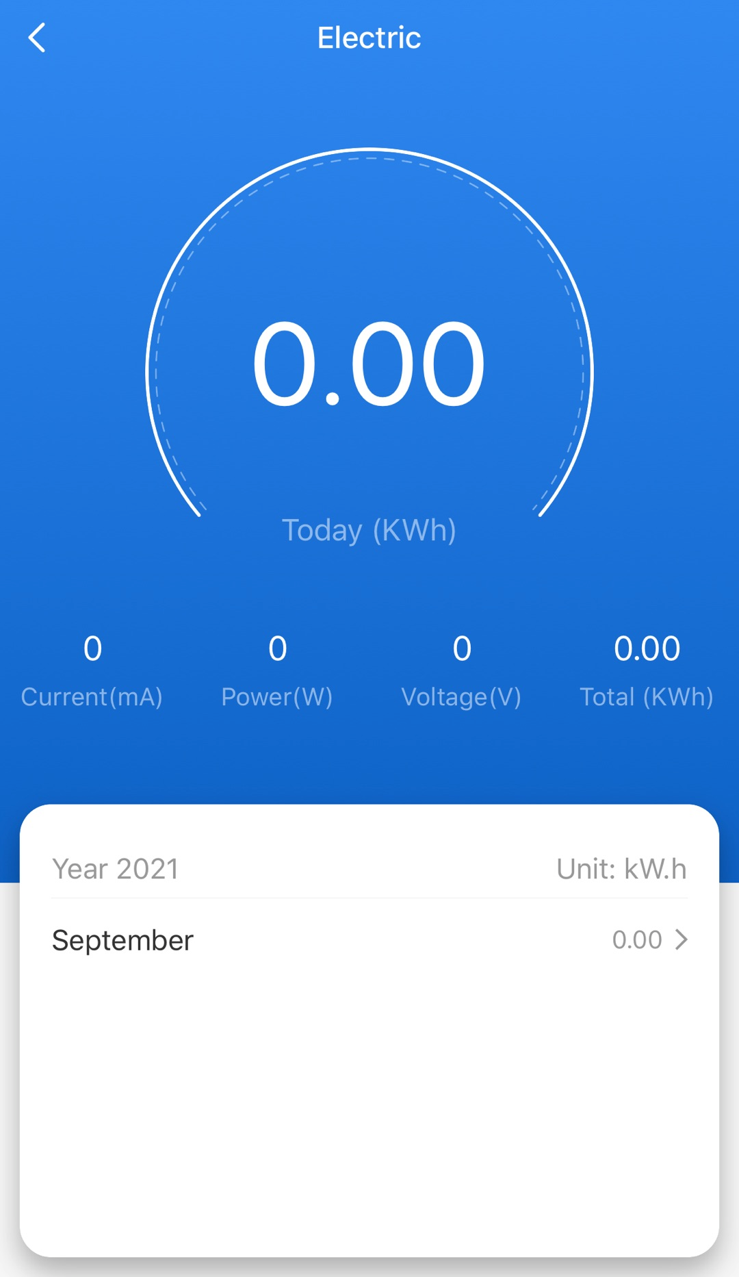
On the control panel, tap the socket icon to power it on. Tap Electric and view data such as voltage, current, and power.
-
View the voltage, current, and power to determine whether the socket works as expected. Typically, the voltage, current, and power of a socket without load is 220V (close to 220V), 0 mA, and 0w respectively. If any of the following situations occurs, it indicates the socket does not work properly.
-
Without load, the voltage, current, and power have values, but the value is abnormal or fluctuates.
-
Without load, the voltage value is or close to 220V, but the values of current and power are abnormal or fluctuate.
-
With load, the voltage, current, and power have values, but the value is abnormal or fluctuates.
-
With load, the voltage value is or close to 220V, but the values of current and power are abnormal or fluctuate.
-
Calibrate parameters
Calibrate parameters based on the values displayed on the mobile app in the previous step.
-
After calibration, reset the socket and pair it again. Repeat the previous step several times to check whether the voltage, current, and power have normal values each time. If so, it indicates the socket can work properly.
-
If calibration fails, perform the following steps to continue troubleshooting.
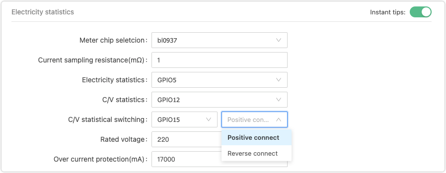
Check the hardware configuration
-
Check whether the hardware configuration you specified on the Tuya Developer Platform matches your circuit design. Note that the selection (SEL) pin can be configured as Positive connect or Reverse connect.
Positive connect
- When the module outputs high level pulse, the energy metering IC receives high level pulse.
- When the module outputs low level pulse, the energy metering IC receives low level pulse.
Reverse connect
-
When the module outputs high level pulse, the energy metering IC receives low level pulse.
-
When the module outputs low level pulse, the energy metering IC receives high level pulse.
Things to note
If you use an optocoupler solution, take care of the SEL pin connection. The SEL pin outputs a pulse signal to the energy metering IC through the module. Therefore, the output pin of the module must be connected to the cathode of the optocoupler, and the SEL pin of the energy metering IC must be connected to the anode (collector) of the optocoupler, as shown in the following schematic diagram.

-
Check whether the pin connection on your PCB follows the schematic and whether your hardware solution is correct.
Check the power supply circuit
-
If you use a non-isolated buck converter, it must work with the rectifier diode.
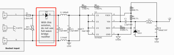
-
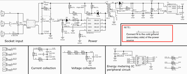
If you use an isolated fly-buck converter, the N (or L) must be connected to the cold ground (secondary side) of the power source for the energy metering IC.
Check the energy metering IC
Troubleshoot single trace layout
-
PCB layout mistake 1:
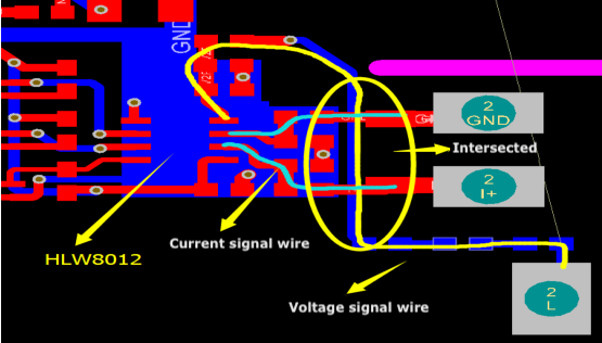
Things to note
-
The voltage signal wire and the current signal wire are intersected. For the current signal, the maximum input voltage is 30.9/50 mV, and the minimum voltage is around 30 nV, so the signal is weak. If the voltage signal wire is routed under the current signal wire, the 220V DC voltage will pose high interference to the current signal.
-
If such trace layout is unchangeable, you can use a resistor to step down the 220V DC voltage before the voltage, and current signal wires are intersected.
-
-
PCB layout mistake 2:
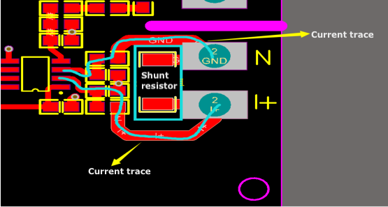
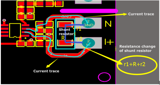
Things to note
-
The signal wire should be started at the ends of the shunt resistor instead of the position shown in the first figure above.
-
The resistance value of the current-sense shunt resistor is not R but r1+R+r2, as shown in the second figure above.
The r1 and r2 are the internal resistance of the plate.
However, such trace layout has its shortcoming. If the PCB cannot handle high temperature well, the high input current can cause excess heat on the PCB, then the resistance value of r1 and r2 will be affected, and eventually, inaccurate signals are fed to the metering IC HLW8012. Therefore, the accuracy of the measurement will be greatly compromised, with about a deviation of 4%. According to Ohm’s law
V = I × (r1+R+r2), the resistance change of r1 and r2 will affect the linearity. Therefore, the higher the power, the greater the deviation.
-
-
PCB layout reference
-
Top layer:
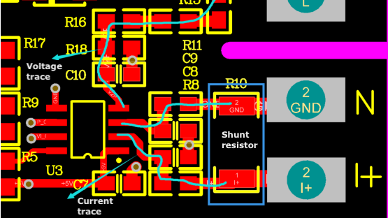
Things to note
-
Use differential routing for current signal wires. Try to place the two differential signal wires in parallel.
-
Try to avoid the intersection of the current and voltage signal wires.
-
As the isolated signal, the GND wire of the differential signal wire is routed across the shunt resistor and connected to the signal terminal of HLW8012. Do not connect it to other GND terminals.
-
-
Bottom layer:
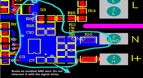
Things to note
-
Even though one of the differential signal wires can be treated as a GND wire in terms of electrical characteristics, make sure to handle it as a signal wire and do not connect it to other GND terminals.
-
Signal trace design
The trace between the energy metering IC and the module should be routed as short as possible. Ensure the signal wires will not be susceptible to interference from components such as inductances and power wires. -
Test interference from VCC and GND
Weld the capacitors to the ground of the V1P and V1N on the energy metering IC to short these two pins. Power on the socket and view the values of current and power on the mobile app. If these two parameters have values, it is caused by noise on the VCC or GND. You need to troubleshoot PCB layout and power supply traces. Possible mistakes in PCB design:
-
The energy metering IC is placed under the power inductor.
-
The V1P and V1N on the energy metering IC are too close to the high-voltage pin on the relay.
-
5V power supply trace or GND trace is too close to the high-voltage area of the relay.
-
Waveform output from the energy metering IC
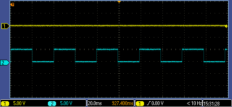
Capture the output of the waveform from the SEL and CF1 pins on the energy metering IC for troubleshooting. The following figures show pulses from HLW8012 IC and BL0937 IC.
Output pulses of HLW8012
Voltage and current pulse signals
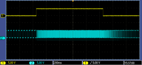
Voltage pulse signal
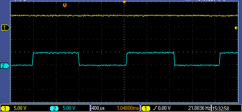
Current pulse signal
-
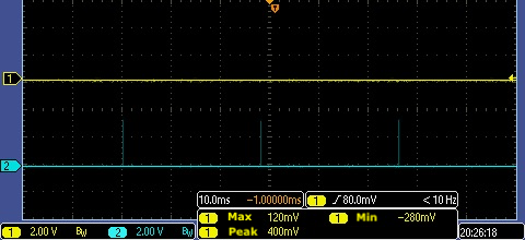
Output pulses of BL0937
Voltage pulse signal
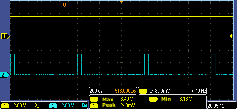
Current pulse signal
-
-
-
Calibration and check the values
After troubleshooting is completed, you can perform calibration and socket pairing again. If the values on the mobile app match the load on the socket, it indicates the issue is resolved.
Is this page helpful?
YesFeedbackIs this page helpful?
YesFeedback


