Wi-Fi & Bluetooth LE MCU Board (WBR3)
The Tuya Sandwich Wi-Fi and Bluetooth LE combo wireless communication board has a WBR3 chip as a microcontroller, which is designed to help you easily prototype your IoT ideas. It can work with functional boards or circuit boards to implement specific features.
Applications
- This board applies to a wide range of prototypes implemented with Tuya’s custom solutions, such as lights, dimmers, remote controls for lights, power strips, switches, home appliances, sensors, and much more.
- Develop with the board to build your IoT projects easily and fast.
- You can use this board for different development purposes.
- Embedded program development and debugging
- App development and debugging
- Creating connected devices that can be controlled with a mobile phone
- Getting started with IoT development and learning how the Wi-Fi-based control system works
Components
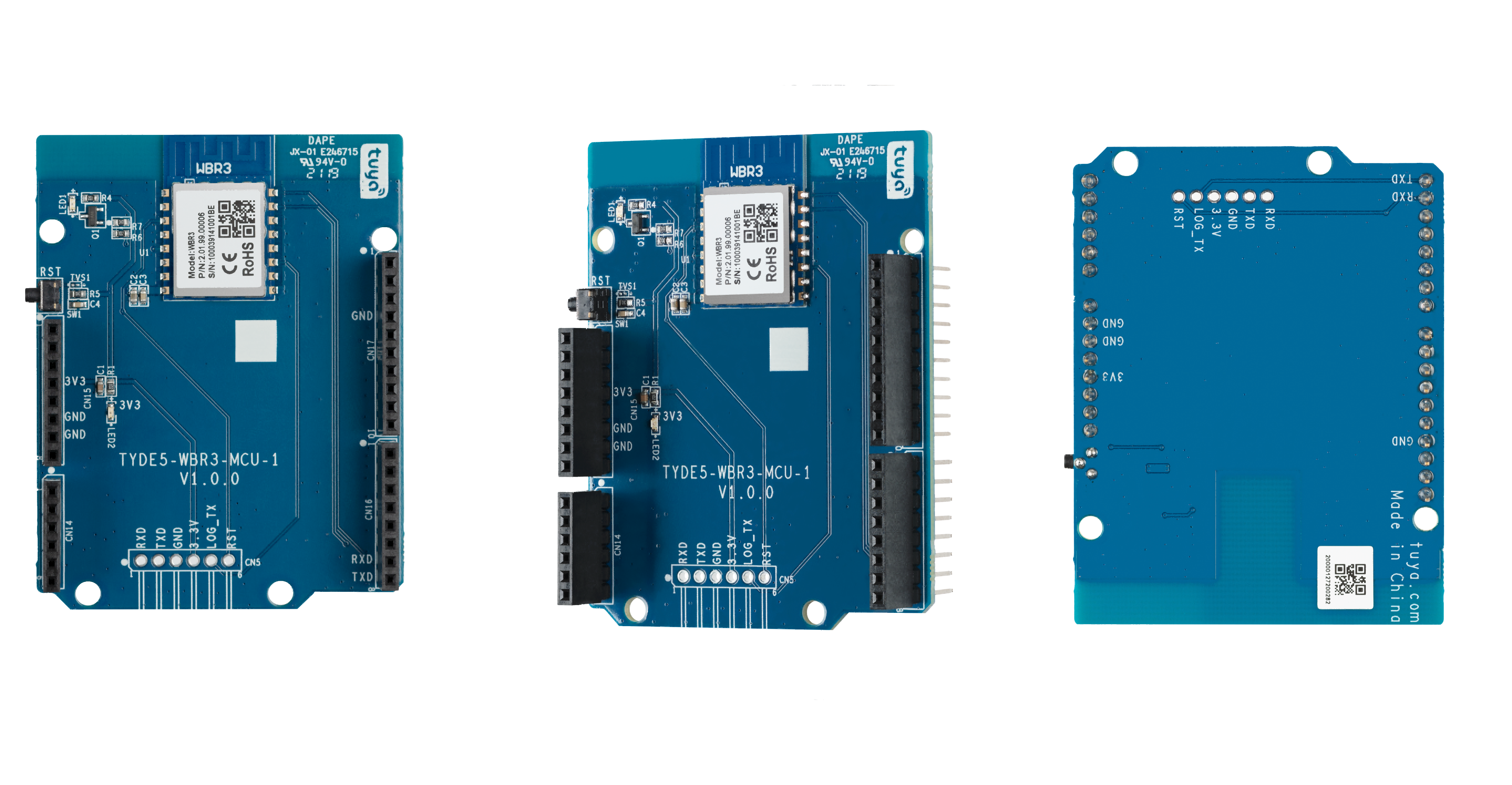
The development board is integrated with Tuya’s proprietary high-performance Wi-Fi and Bluetooth LE combo module WBR3. It has on-board buttons, LED, and more. For more information, see the WBR3 Module Datasheet.
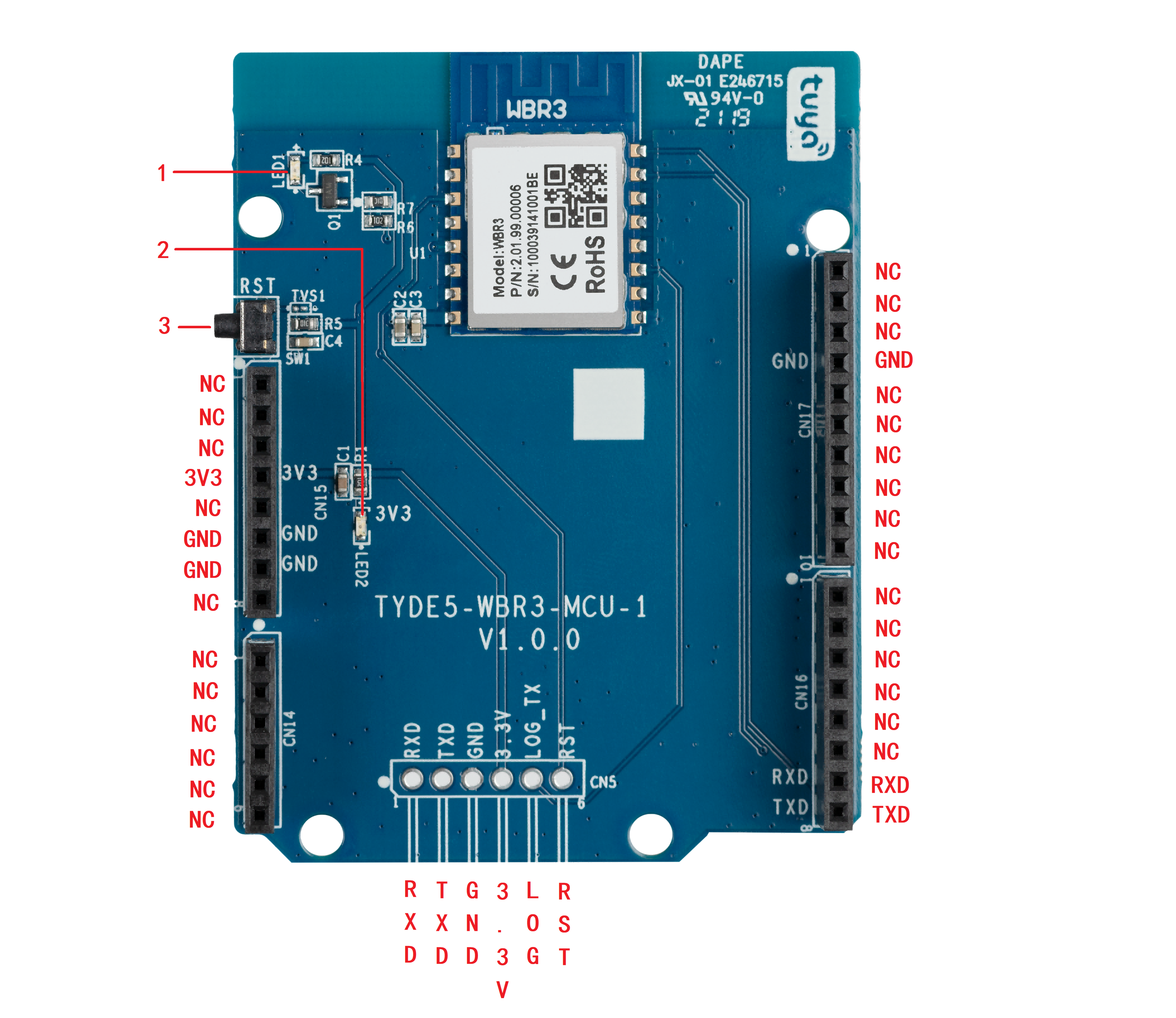
I/O port and pin description
-
1: LED indicator (LED1): When GPIOA_2 outputs high, the LED is on.
-
2: LED indicator (LED2): When the 3.3V power is on, the LED is on.
-
3: Button (SW1): Module’s enable pin that is active low. When the button is pressed, the pin outputs low.
-
Pin description
No. Symbol Description 1 NC Leave it floating. 2 NC Leave it floating. 3 NC Leave it floating. 4 3V3 3.3V power pin. 5 NC Leave it floating. 6 GND Ground pin. 7 GND Ground pin. 8 NC Leave it floating. 9 NC Leave it floating. 10 NC Leave it floating. 11 NC Leave it floating. 12 NC Leave it floating. 13 NC Leave it floating. 14 NC Leave it floating. 15 TXD GPIOA_14, which can be reused as theUART0_TXDpin for serial communication.16 RXD GPIOA_13, which can be reused as theUART0_RXDpin for serial communication.17 NC Leave it floating. 18 NC Leave it floating. 19 NC Leave it floating. 20 NC Leave it floating. 21 NC Leave it floating. 22 NC Leave it floating. 23 NC Leave it floating. 24 NC Leave it floating. 25 NC Leave it floating. 26 NC Leave it floating. 27 NC Leave it floating. 28 NC Leave it floating. 29 GND Ground pin. 30 NC Leave it floating. 31 NC Leave it floating. 32 NC Leave it floating. -
The reserved pin
You can use the reserved pin for license activation, firmware updates, or log printing.No. Symbol Description 1 RXD GPIOA_13, which can be reused as theUART0_RXDpin to activate the license.2 TXD GPIOA_14, which can be reused as theUART0_TXDpin to activate the license.3 GND Ground pin. 4 3.3V 3.3V power pin. 5 LOG The pin for log printing. 6 RST Module’s enable pin that is active low.
Power requirements
-
Power is input through the 3.3V pin. The operating voltage is from 3.0V to 3.6V.
-
Consumption
Mode Status (Ta = 25°C) Average Peak Unit Pairing in EZ mode The module is being paired in EZ mode. 75 324 mA Idle mode The module is connected to the internet. 64 314 mA Working mode The module is connected to the internet. 66 305 mA Disconnected mode The module is disconnected from the internet. 66 309 mA
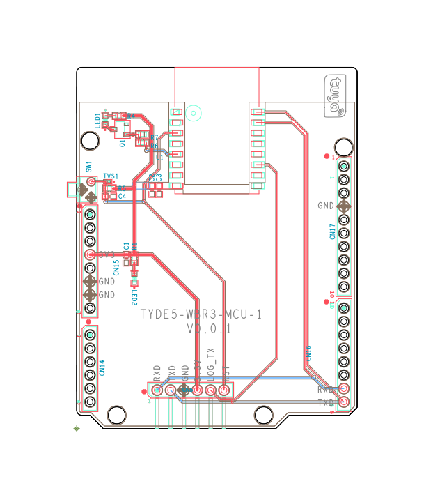
Schematic diagram and PCB
-
The schematic diagram of the board:
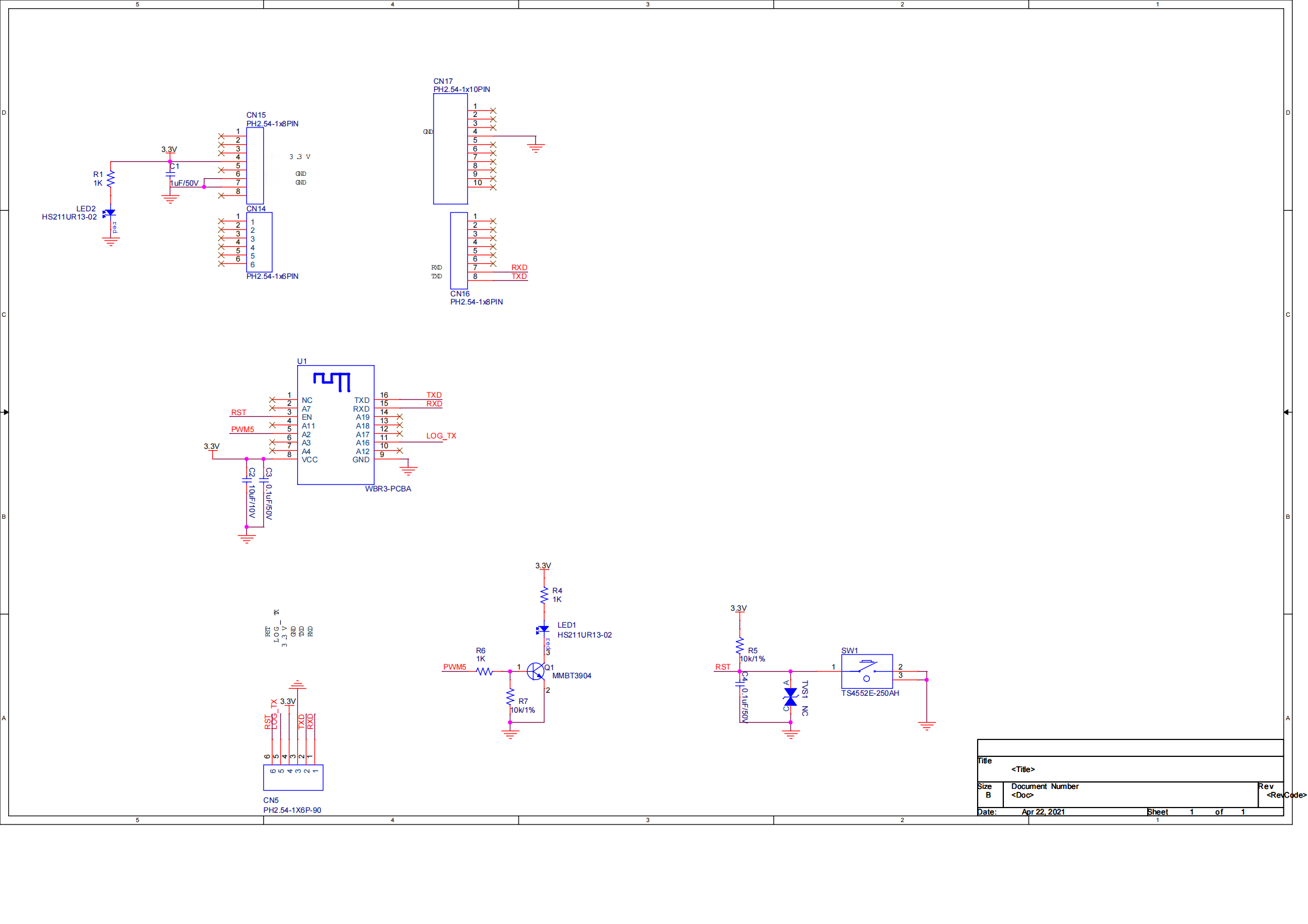
-
The PCB board:
Connection for flashing
For flashing license and firmware, connect pins following the table and figure shown below.
| Communication board | Reserved pins | Pins on USB-to-serial chip | Connector |
|---|---|---|---|
| Wi-Fi & Bluetooth LE Communication Board (WBR3) | 3.3V | 3.3V | Jumper wires |
| TXD | USB-RX | ||
| RXD | USB-TX1 | ||
| GND | GND |
Connection for viewing logs
For flashing license and firmware, connect pins following the table and figure shown below.
| Communication board | Reserved pins | Pins on USB-to-serial chip | Connector |
|---|---|---|---|
| Wi-Fi & Bluetooth LE Communication Board (WBR3) | LOG | USB-RX | Jumper wires |
| GND | GND |
Things to note
- This board does not have a built-in power supply, so an additional power board is necessary.
- This board only supports 3.3V input voltage with a supply current of at least 350 mA.
Is this page helpful?
YesFeedbackIs this page helpful?
YesFeedback


