TYZS3 Module
Scope of application
This topic describes relevant information about the TYZS3 module during MCU connection development.
TYZS3 is a low power embedded Zigbee module developed by Tuya Smart. The module consists of a highly integrated radio-frequency identification (RFID) chip EFR32MG13P732F512GM48 and a few peripheral components, with a built-in 802.15.4 PHY/MAC Zigbee network protocol stack and various library functions. TYZS3 also has a low power 32-bit ARM Cortex-M4 processor, 512 KB flash, 64 KB RAM, and rich peripheral resources. As a FreeRTOS platform, TYZS3 integrates all function libraries of Zigbee MAC and TCP/IP protocols. You can develop your own embedded Zigbee products.
For more information, see TYZS3 Module Datasheet.
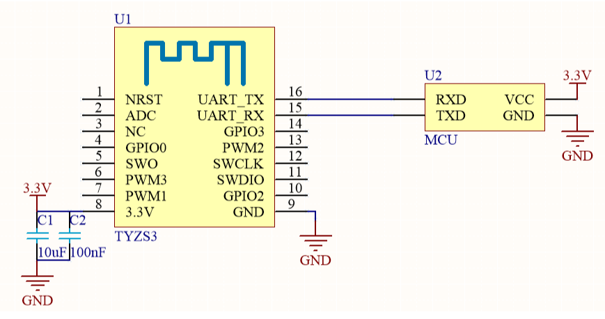
Typical application diagram
-
Reference diagram of coordinated processing mode of the module and 3.3 V MCU
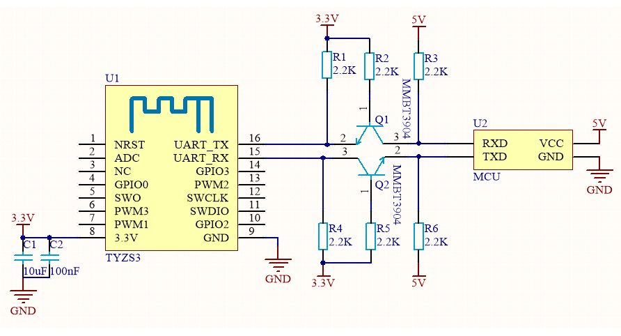
-
Reference diagram of coordinated processing mode of the module and 5 V MCU
Design specification
-
Module power supply:
- When the module is in the emission status, the typical value of the maximum current reaches 120 mA. It is recommended that the supply current of the 3.3V module should exceed 200 mA, and the total capacity of the external filter capacitor should exceed 10 uF.
- Power filter capacitors C1 and C2 shall be arranged near the power supply pin.
-
Module pin:
- The nRST pin only resets the module hardware, but cannot clear Zigbee pairing information.
- The ADC port can be used as an ordinary I/O port. When not in use, the pin can float. As the ADC input port, the input voltage ranges from 0 V to AVDD, which is configured in the software.
- For more information, see the module datasheet.
-
Radio frequency (RF) of the module:
-
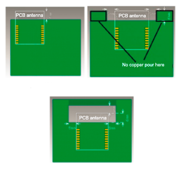
The module has a PCB onboard antenna by default.
-
When a PCB onboard antenna is used in the Zigbee module, it is recommended that the distance between the module antenna and other metal parts should be at least 15 mm, in order to optimize the wireless performance. It is recommended that the antenna area corresponding to the adapter board should be hollowed out to achieve the best performance. Wiring and copper pour are not allowed in the antenna area of the PCB, in order not to affect the antenna performance. Make sure that no substrate medium exists directly below or above the printed antenna, and the printed antenna is away from the copper sheet. In this way, the antenna radiation effect is guaranteed to the maximum extent.
-
Is this page helpful?
YesFeedbackIs this page helpful?
YesFeedback


