Zigbee Module Design for Gateways
This topic describes information about Zigbee module design for implementing gateway products.
Scope
This topic applies to the following Zigbee models.
| Module model | Input voltage (TYP) |
Typical current in continuous TX (250 kbps/+19 dBm) |
Typical current in continuous RX (250 kbps) |
Typical current in deep sleep mode |
|---|---|---|---|---|
| TYZS5 | 3.3V | 118 mA | 8 mA | 5 μA |
| TYZS3 | 3.3V | 120 mA | 8 mA | 5 μA |
| TYZS13 | 3.3V | 120 mA | 8 mA | 5 μA |
You can develop your own embedded Zigbee products, such as gateways. For more information, see the module datasheet.
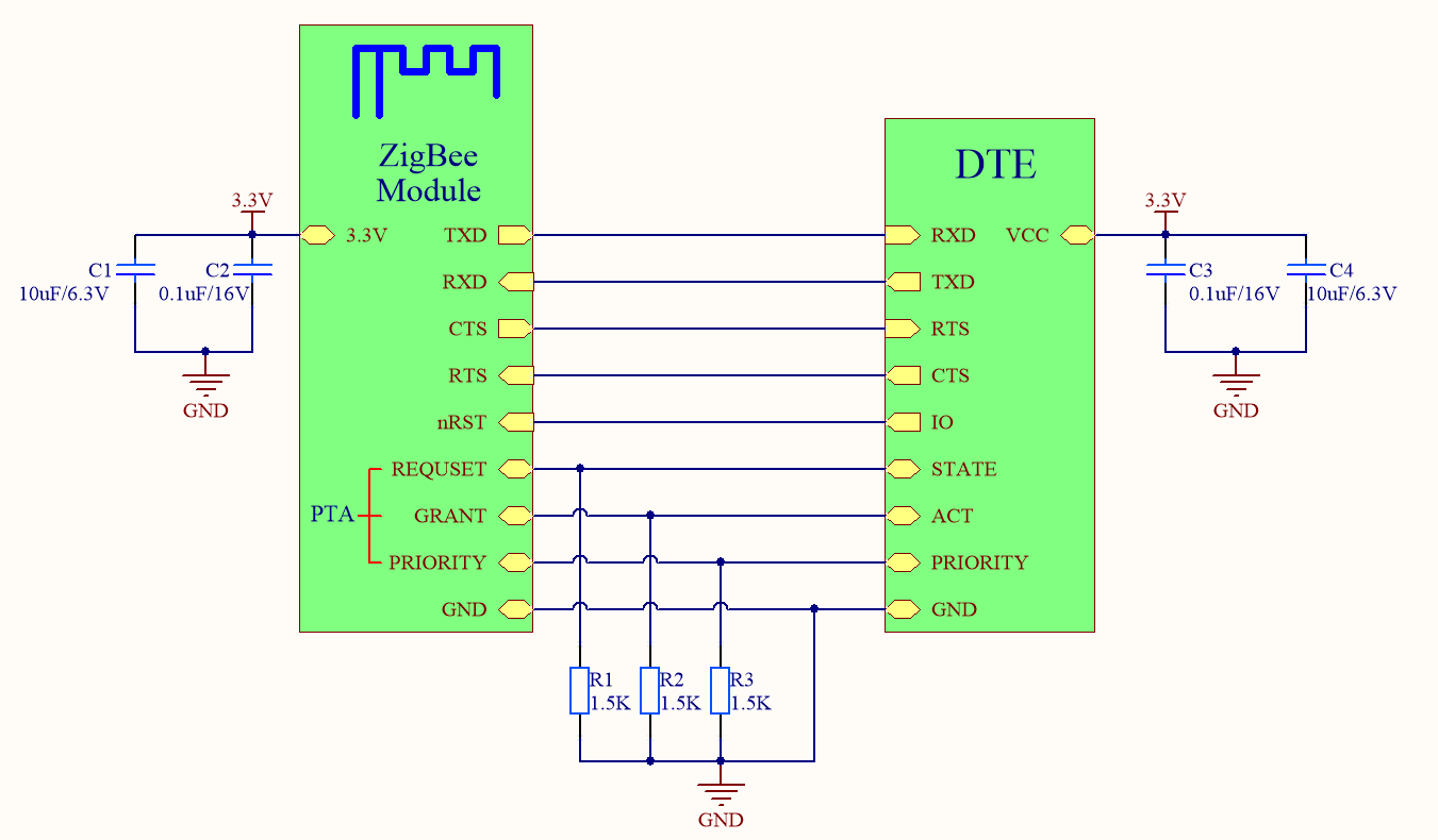
Typical application circuit
-
Connection between a module and a 3.3V MCU
-
Pin configuration
Module model TXD RXD CTS RTS nRST REQUSET GRANT PRIORITY TYZS5 UART_TX(PA0) UART_RX(PA1) PWM1(PA4) PWM2(PA3) nRST - - - TYZS3 UART_TX(PA0) UART_RX(PA1) PWM3(PF4) PWM2(PA2) nRST ADC(PB11) GPIO0(PA3) SWO(PF2) TYZS13 UART_TX(PA0) UART_RX(PA1) PWM3(PF4) PWM2(PA2) nRST ADC(PB11) GPIO0(PA3) SWO(PF2) - TYZS5 module does not support packet traffic arbitration (PTA).
- Place a 1.5K pull-down resistor on the PTA pin.
Design specification
-
Power supply
Module model Maximum transmit power (250 kbps/+19 dBm) Receive power (250 kbps) TYZS5 118 mA 8 mA TYZS3 120 mA 8 mA TYZS13 120 mA 8 mA - The supply current for 3.3V modules must be greater than 200 mA. The total capacity of the external filter capacitor should be greater than 10 μF.
- Place the filter capacitors of the power input pin near the power pin of the module.
-
Radio frequency:
- You can connect the ZYZS13 module to a copper wire antenna with through-hole soldering. Alternatively, use an external with an IPEX connector if your circuit is complex.
- If you choose a copper wire antenna, the distance between the antenna and other mental components should be at least 15 mm to provide the best radiation performance. It is recommended to hollow out the breakout board around the antenna area. Make sure that the enclosure surrounding the antenna is not traced or filled with copper. Otherwise, the radiation performance might be degraded.
-
Antenna clearance description
-
Do not use metal shells or plastic shells with metallic paint or coating in the direction of the antenna radiation. Do not use metal objects such as screws and rivets near the antenna, which might affect the antenna efficiency.
-
Try to increase the distance from the top shell to the antenna to minimize the impact on antenna performance.
-
Try to increase the distance from the upper and bottom shells to the antenna to minimize the impact on antenna performance.
-
Keep the module away from speakers, power switches, cameras, HDMI, USB, and other high-speed signals to avoid interference.
-
Avoid metal shielding near the antenna. If co-channel interference occurs, you must evaluate the impact on the antenna performance and ensure the isolation from interference.
-
-
Placement
-
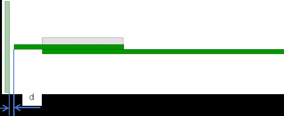
Horizontal placement
We recommend that you place the module at the edge of the backplane with the antenna facing outward, and flush the module’s GND terminal with the backplane’s GND terminal. Both terminals are fully connected.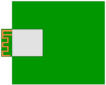
-
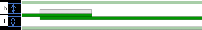
Embedded placement
Embed the module into the backplane through a slot that is flushed with or deeper than the module’s GND terminal. The side of the slot must be 15 mm or farther from the module’s board edge.
A wider slot can achieve better performance that is still weaker than that of horizontal placement.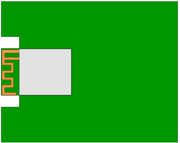
-
Vertical placement
Insert the module vertically into the backplane slot with the antenna facing upward. The module’s GND terminal and the backplane’s GND terminal must be fully connected. We recommend that you keep a clearance distance of 15 mm or more around the antenna. -
PCB antenna is the default type of antenna.
-
If you choose a PCB antenna, the distance between the antenna and other mental components should be at least 15 mm to provide the best radiation performance. Make sure that the enclosure surrounding the antenna is not traced or filled with copper. Otherwise, the radiation performance might be degraded. It is recommended to hollow out the breakout board around the antenna area.
-
Is this page helpful?
YesFeedbackIs this page helpful?
YesFeedback


