MCU Integration Protocol for Zigbee Lock
This topic describes the general integration solution for door locks developed based on Tuya Zigbee SDK. This topic helps you get to know Tuya Zigbee lock integration and development process, and complete the development quickly.
Terms
| Term | Definition |
|---|---|
| Extra-low voltage (ELV) device | A battery-powered device, which is called a sleep end device in the Zigbee protocol. |
| TYZS5 module | A small Zigbee module suitable for developing sensor devices. |
For more information, see Terms.
Hardware connection
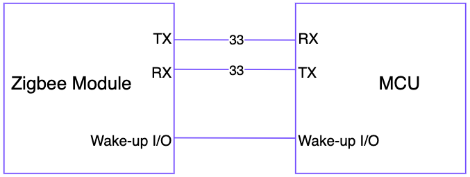
Tuya Zigbee modules and MCU master control are both powered by DC 3.3V.
The UART communication Baud between the Tuya Zigbee module and MCU is set to 115200-8-N-1, and there is no data flow control. The UART interface pins use standard logic. In the idle status, the TXD and RXD pins are both high level, with the low level as the start bit and the high level as the stop bit. Even if the device enters the sleep status, the pin remains a high level.
A reserved GPIO port connection between the Zigbee module and the MCU is used by the module to wake up the MCU. The default setting is the internal pull-up status, and it is effective when pulled down for 10 ms. The MCU wakes up the Zigbee module through serial commands. If the device is an electrical device, the MCU only needs to make a handshake connection when it is powered on for the first time. If the device is an ELV device with the sleep function, in addition to the power-on handshake connection, the MCU also needs to make a handshake connection before actively sending a command.
Timeout
-
UART response timeout: 500 ms.
When the module’s serial port receives the MCU’s wake-up frame or its response frame, it will be woken up for 500 ms. At this time, the MCU can send other data. If the two frames of data are sent with an interval of 500 ms, a wake-up frame needs to be added between them.
-
Response timeout of the wake-up frame: 20 ms.
After the module sends the wake-up frame, the MCU shall respond within 20 ms. Otherwise, the module will retransmit the wake-up frame twice each time. When the response frame from the MCU is still not received after three transmissions, the data to be sent will be saved in the sending queue, and it will be sent again when the MCU is woken up next time.
Frame format
- Baud: 115200
- Data bit: 8
- Parity check: none
- Stop bit: 1
- Data flow control: none
- MCU: Micro Controller Unit. MCU is connected to Tuya modules through serial ports. Regarding the protocol design, the interaction of all packets is designed as full-duplex communication.
Frame format description
| Field | Length (byte) | Description |
|---|---|---|
| Header | 2 | It is fixed as 0x55aa |
| Version | 1 | It is used for update and extension |
| Sequence | 2 | Sequence of the business |
| Command | 1 | Specific frame type |
| Data length | 2 | Big-endian (length is N) |
| Data | N | Effective data transmitted |
| Checksum | 1 | Start from the header, add up all the bytes, and then divide the sum by 256 to get the remainder |
Note:
-
All data greater than one byte shall be transmitted in big-endian mode.
-
All examples in the protocol use hexadecimal data.
-
Generally, one command is sent by one party and received by the other party in a synchronous way. That is, one party sends the command, and the other party responds. If the sender does not receive the correct response packet, the transmission times out, as shown in the following figure:
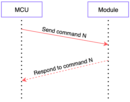
-
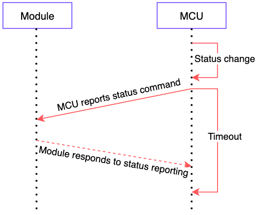
Sending module control command and reporting MCU status works in an asynchronous way. Assuming that the module control command is "x", and the command of MCU status report is "y", the data transmission is as follows:
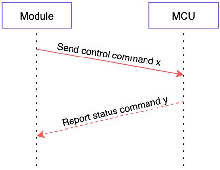
MCU status reporting is divided into passive reporting and active reporting.
-
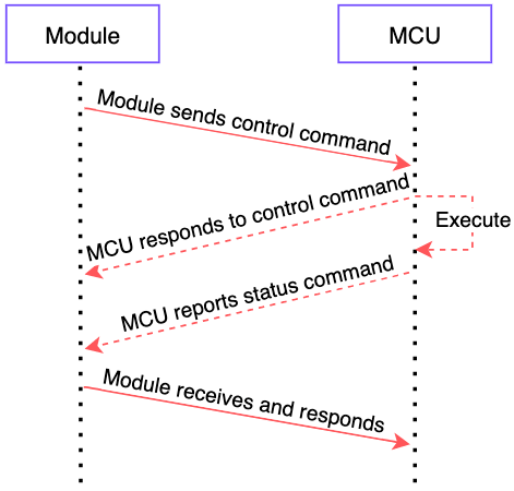
Passive reporting: The module sends data commands to the MCU, and the MCU returns the status after execution.
-
Active reporting: When the status of the MCU changes (physical operation or power off and restart), the current status is actively reported to the module. Active reporting of the MCU is an asynchronous operation. If the status report response frame is not received within the timeout period, or the status in the received response frame is unsuccessful, the MCU must retransmit the status data.
-
DP data unit format
Control commands and status data are all represented in DP data unit format.
DP command/status data unit is shown as follows:
| Data segment | Length (byte)
| Description || ------ | ------------ | ----- | -------- |
| Dpid | 1 | DP serial number. |
| Type | 1 | The specific data type of a data point in the Tuya Developer Platform, which is represented by the following "Value". |
| Len | 2 | The length corresponds to the byte number of the value. |
| Value | 1/2/4/N | Represented by hex values. Big-endian transmission is adopted when there is more than one byte. | |
Type:
| Type | Value | Length (byte) | Description |
|---|---|---|---|
| raw | 0x00 | N | Correspond to raw data points (module pass-through). |
| bool | 0x01 | 1 | Value range: 0x00/0x01. |
| Value | 0x02 | 4 | Corresponding to the integer type, in big endian format. |
| string | 0x03 | N | Correspond to specific strings. |
| enum | 0x04 | 1 | Enumeration type, ranging from 0 to 255. |
| bitmap | 0x05 | 1/2/4 | Represented by big-endian when there is more than one byte. |
For DP commands and status data units, except the "raw" type, all other types belong to the "obj" type data points.
- "Send command" can contain "command data units" of multiple DPs.
- "Send command" uses asynchronous processing protocol, corresponding to the DP "status report" of the MCU.
Protocol details
Wake-up
Zigbee wakes up MCU and MCU wakes up Zigbee by using this command. This command will be re-sent three times, and each timeout period is 20 ms. Until the response packet is received, it is woken up and starts to receive data within a maximum of 500 ms. It will enter sleep after 500 ms. If it receives a non-wake-up command in the wake-up status, the wake-up time period will not be delayed. This command is preceded by a 7-byte preamble.
The module sends the following command:
| Field | Length (byte) | Description |
|---|---|---|
| Header | 2 | 0x55aa |
| Version | 1 | 0x03 |
| Sequence (Seq) | 2 | 55AA (fixed serial number) |
| Command | 1 | 0x00 |
| Data length | 2 | 0x0000 |
| Checksum | 1 | Start from the header, add up all the bytes, and then divide the sum by 256 to get the remainder. |
The MCU returns the following command:
| Field | Length (byte) | Description |
|---|---|---|
| Header | 2 | 0x55aa |
| Version | 1 | 0x03 |
| Sequence (Seq) | 2 | 55AA (fixed serial number) |
| Command | 1 | 0x00 |
| Data length | 2 | 0 |
| Checksum | 1 | Start from the header, add up all the bytes, and then divide the sum by 256 to get the remainder. |
Note: When the module actively wakes up the MCU, the serial number is fixed at 55 AA, and the ACK serial number returned by the MCU is also 55 AA.
When the MCU actively wakes up the module, the serial number is fixed at 00 00, and the ACK serial number returned by the module to the MCU is also 00 00.
Example
-
The module sends the following command:
0x00 00 00 00 00 00 00 55 AA 03 55 AA 00 00 00 01 -
The MCU responds:
0x55 AA 03 55 AA 00 00 00 01 -
The MCU sends the following command:
0x00 00 00 00 00 00 00 55 AA 03 00 00 00 00 00 02 -
The module responds:
0x55 AA 03 00 00 00 00 00 02
Query product information
PID: corresponding to the product ID (PID) in the Tuya Developer Platform. It is generated by the Tuya Developer Platform to record product information in the cloud.
Product information consists of the product ID and MCU software version number.
Define the format of MCU software version No.: Use dot-decimal notation, "x.x.x" (0 ≤ x ≤ 99), and "x" is a decimal digit.
The module sends the following command:
| Field | Length (byte) | Description |
|---|---|---|
| Header | 2 | 0x55aa |
| Version | 1 | 0x03 |
| Sequence (Seq) | 2 | Generate sequentially. |
| Command | 1 | 0x01 |
| Data length | 2 | 0x0000 |
| Data | 0 | None |
| Checksum | 1 | Start from the header, add up all the bytes, and then divide the sum by 256 to get the remainder. |
For example, 0x55 AA 03 33 77 01 00 00 AD
The MCU returns the following command:
| Field | Length (byte) | Description |
|---|---|---|
| Header | 2 | 0x55aa |
| Version | 1 | 0x03 |
| Sequence (Seq) | 2 | Seq sent by the module |
| Command | 1 | 0x01 |
| Data length | 2 | N |
| Data | N | {"p":”AIp08kLI”, "v":”1.0.0” } |
| Data | 1 | Whether to support OTA. 1: support. 0: not support. |
| Checksum | 1 | Start from the header, add up all the bytes, and then divide the sum by 256 to get the remainder. |
For example, {"p":”8s4uquyx”,"v":”1.0.0”}
-
p represents product ID, 8s4uquyx, which is the product ID created by the user on the Tuya Developer Platform.
-
v represents the MCU version number, which is 1.0.0.
MCU returns example information:
0x55 AA 03 33 77 01 00 1C 7B 22 70 22 3A 22 38 73 34 75 71 75 79 78 22 2C 22 76 22 3A 22 31 2E 30 2E 30 22 7D 01 7F
Header version Seq command data length { " p " : " 8 s 4 u q u y x " , **" v " : " 1 . 0 . 0 " } ** checksum
Query network status of the module
The following table is the network status table of the module, where 0x00 to 0x05 are the network status of the module, and 0x10 to 0x80 are the results of data transmission, which are used in the following protocol transmission.
| Device status ID | Description |
|---|---|
| 0x00 | The device is not connected to the gateway. |
| 0x01 | The device is connected to the gateway. |
| 0x02 | The device is connected to the server. |
| 0x03 | The device is connected to the gateway and the server. |
| 0x04 | The device is not connected to the server. |
| 0x05 | The device is connected to the gateway but is not connected to the server. |
| 0x10 | It is reported that the transmission succeeded. |
| 0x20 | It is reported that the transmission failed. |
| 0x40 | It is reported that the transmission timed out. |
| 0x80 | It is reported that the transmission is busy. |
Note:
- The device is not connected to the network: The device is powered on for the first time, fails to connect to the network, or is off the network. This status is sent to the MCU.
- The device is connected to the network: The device is successfully connected to the network. This status is sent to the MCU.
- When the module detects that the MCU reboots or is disconnected and then go back online, the module will send its network status to the MCU.
- When the network status of the module changes, the module network status is actively sent to the MCU.
The MCU sends the following command:
| Field | Length (byte) | Description |
|---|---|---|
| Header | 2 | 0x55aa |
| Version | 1 | 0x03 |
| Sequence (Seq) | 2 | Generated by the MCU |
| Command | 1 | 0x02 |
| Data length | 2 | 0x0000 |
| Data | 0 | None |
| Checksum | 1 | Start from the header, add up all the bytes, and then divide the sum by 256 to get the remainder. |
For example, 0x55 AA 03 00 00 02 00 00 04
The module returns the following command:
| Field | Length (byte) | Description |
|---|---|---|
| Header | 2 | 0x55aa |
| Version | 1 | 0x03 |
| Sequence (Seq) | 2 | Seq sent by the MCU |
| Command | 1 | 0x02 |
| Data length | 2 | 0x0001 |
| Data | 1 | Indicate the working status of the module. For Zigbee status, see the above table (0x00 to 0x05). |
| Checksum | 1 | Start from the header, add up all the bytes, and then divide the sum by 256 to get the remainder. |
For example, 0x55 AA 03 00 00 02 00 01 03 08
Configure Zigbee module
In the case of an ELV device, the MCU shall send a wake-up command to the module first, and then send a configuration command to the module. In the case of an electrical device, the MCU directly sends a configuration command to the module.
There are three types of commands to configure the Zigbee module, as shown below.
| Command | Description |
|---|---|
| 0x00 | Reset the module to factory defaults (not connected to the network). |
| 0x01 | Configure the module to start network configuration. |
| 0x02 | Notify that the MCU restores factory defaults. |
Note: When the MCU is restored to factory defaults, the MCU shall send a 0x02 command to the Zigbee module, telling the Zigbee module that it has been restored to the factory defaults.
Restore factory defaults locally: Report No. 25 DP through the 0x23 command to Zigbee, whereas Zigbee transparently transmits it to the cloud and sends this command after receiving the response from the cloud. This command tells the Zigbee module to clear the local offline password.
The cloud sends the command of restoring factory defaults: First respond while send the notification of restoring factory defaults to tell the Zigbee module to clear the local offline password.
The MCU sends the following command:
| Field | Length (byte) | Description |
|---|---|---|
| Header | 2 | 0x55aa |
| Version | 1 | 0x03 |
| Sequence (Seq) | 2 | Generated by the MCU |
| Command | 1 | 0x03 |
| Data length | 2 | 0x0001 |
| Data | 1 | 0x00/0x01 |
| Checksum | 1 | Start from the header, add up all the bytes, and then divide the sum by 256 to get the remainder. |
For example, 0x55 AA 03 00 00 03 00 01 01 07
The module returns the following command:
| Field | Length (byte) | Description |
|---|---|---|
| Header | 2 | 0x55aa |
| Version | 1 | 0x03 |
| Sequence (Seq) | 2 | Seq sent by the MCU |
| Command | 1 | 0x03 |
| Data length | 2 | 0x0001 |
| Data | 1 | 0x00: OK. 0x01: error. |
| Checksum | 1 | Start from the header, add up all the bytes, and then divide the sum by 256 to get the remainder. |
For example, 0x55 AA 03 00 00 03 00 01 00 06
Send data command
The module sends the following command:
| Field | Length (byte) | Description |
|---|---|---|
| Header | 2 | 0x55aa |
| Version | 1 | 0x03 |
| Sequence (Seq) | 2 | Generate sequentially. |
| Command | 1 | 0x04 |
| Data length | 2 | It depends on types and the number of "command data units". |
| Data | N | DP data |
| Checksum | 1 | Start from the header, add up all the bytes, and then divide the sum by 256 to get the remainder. |
For example, 0x55 AA 03 00 1C 04 00 05 0E 04 00 01 00 3A
Header version Seq command data length DPID DP type data length data checksum
The MCU returns the following command:
| Field | Length (byte) | Description |
|---|---|---|
| Header | 2 | 0x55aa |
| Version | 1 | 0x03 |
| Sequence (Seq) | 2 | Seq sent by the module |
| Command | 1 | 0x04 |
| Data length | 2 | 0x0001 |
| Data | 1 | 0x00: OK. 0x01: error. |
| Checksum | 1 | Start from the header, add up all the bytes, and then divide the sum by 256 to get the remainder. |
For example, 0x55 AA 03 00 1C 04 00 01 00 23
Header version Seq command data length data checksum
Report the real-time status
Scenario: If a device has an alert function and requires real-time notification, you can use this command to report the relevant status data.
Note: When the MCU needs to report real-time status data, this protocol can be used to report the data.
Status data is directly reported to the cloud, so the device shall be connected to the cloud already. Otherwise, the device fails to report the data.
This command is a synchronous command. MCU reports the data and then waits for the result returned by the module. The waiting timeout is five seconds.
The module sends a network status packet of successful server connection, and then sends the required statistical data packet. The data uploading does not have storage function. If it fails to receive the network status packet of successful server connection within eight seconds, the device will be powered off forcibly.
Support the reporting of multiple data units and single data unit. You can select the packet sending mode as needed. For more information about the data packet, see the following example.
The MCU sends the following command:
| Field | Length (byte) | Description |
|---|---|---|
| Header | 2 | 0x55aa |
| Version | 1 | 0x00 |
| Sequence (Seq) | 2 | Generated by the MCU |
| Command | 1 | 0x05 |
| Data length | 2 | It depends on types and the number of "status data units". |
| Data | N | One or multiple combined "status data unit" groups. |
| Checksum | 1 | Start from the header, add up all the bytes, and then divide the sum by 256 to get the remainder. |
The module returns the following command:
| Field | Length (byte) | Description |
|---|---|---|
| Header | 2 | 0x55aa |
| Version | 1 | 0x00 |
| Sequence (Seq) | 2 | Seq sent by the MCU |
| Command | 1 | 0x05 |
| Data length | 2 | 0x0001 |
| Data | 1 | Refer to module network status table. |
| Checksum | 1 | Start from the header, add up all the bytes, and then divide the sum by 256 to get the remainder. |
Zigbee notification
It includes Zigbee asynchronous notification or notification of network status changes.
The module sends the following command:
| Field | Length (byte) | Description |
|---|---|---|
| Header | 2 | 0x55aa |
| Version | 1 | 0x03 |
| Sequence (Seq) | 2 | Generate sequentially. |
| Command | 1 | 0x06 |
| Data length | 1 | 0x02 |
| Zigbee status | 1 | Zigbee status |
| Checksum | 1 | Start from the header, add up all the bytes, and then divide the sum by 256 to get the remainder. |
For example, send "network status": 0x55 AA 03 00 77 06 00 01 05 85
Header version Seq command data length data checksum
The MCU returns the following command:
| Field | Length (byte) | Description |
|---|---|---|
| Header | 2 | 0x55aa |
| Version | 1 | 0x03 |
| Sequence (Seq) | 2 | Seq sent by the module |
| Command | 1 | 0x06 |
| Data length | 2 | 0x0001 |
| Data | 1 | Refer to module network status table. |
| Checksum | 1 | Start from the header, add up all the bytes, and then divide the sum by 256 to get the remainder. |
For example, respond with "network status": 0x55 AA 03 00 77 06 00 01 10 90
Header version Seq command data length data checksum
Request dynamic password
The time data in the protocol is used to operate the current dynamic password. The operation time is the current Greenwich Mean Time (GMT). Therefore, the device is required to send GMT data to the module.
The app can set whether to add the administrator password to participate in the mixed operation result of the dynamic password. Every time the device requests to verify the dynamic password, the device shall send all the administrator passwords of the lock to the module.
The data length of the sent packet is at least 15 bytes, including time data + password + the number of transmitted administrator passwords.
The MCU sends the following command:
| Field | Length (byte) | Description |
|---|---|---|
| Header | 2 | 0x55aa |
| Version | 1 | 0x03 |
| Sequence (Seq) | 2 | Generated by the MCU |
| Command | 1 | 0x07 |
| Data length | 2 | xx xx |
| Data | 4 | Current GMT of the device: data[0]–data[3] |
| 8 | Password data entered by the user: Data[4]–Data[11]. The data content ranges from 0 to 9 and the ASCII code is used for data transmission. | |
| 1 | The number of administrator passwords (0–10). | |
| 1 | The length of the first password (no more than eight bytes) | |
| n | The first administrator password must consist of figures. The data content ranges from 0 to 9, and the ASCII code is used for data transmission. | |
| 1 | The length of the second password (no more than eight bytes) | |
| n | The second administrator password must consist of figures. The data content ranges from 0 to 9, and the ASCII code is used for data transmission. | |
| … | … | |
| Checksum | 1 | Start from the header, add up all the bytes, and then divide the sum by 256 to get the remainder. |
For example, 55 AA 03 00 00 07 00 1D 5B BC 3A 41 33 37 32 32 34 32 30 31 02 06 30 31 32 33 34 35 08 31 32 33 34 35 36 37 38 30
Header version Seq command data length timestamp****dynamic password the number of administrator passwords length of the first password the first administrator password length of the second password the second administrator password checksum
The module returns the following command:
| Field | Length (byte) | Description |
|---|---|---|
| Header | 2 | 0x55aa |
| Version | 1 | 0x03 |
| Sequence (Seq) | 2 | Seq sent by the MCU |
| Command | 1 | 0x07 |
| Data length | 2 | 0x0001 |
| Data | 1 | 0x00: Password verification passed. 0x01: Password verification failed.//0x02: The device did not get the SecKey. 0x03: Data length error. |
| Checksum | 1 | Start from the header, add up all the bytes, and then divide the sum by 256 to get the remainder. |
For example, 55 AA 03 00 00 07 00 01 00 0A
Report offline password
When the user enters the offline password on the MCU, the MCU shall report the password to Zigbee. Zigbee verifies the password and sends the result to the MCU. Then, the MCU determines whether to open the door accordingly.
The length of the offline password is 10 bytes. When the password entered by the user is 10 bytes, it is considered that this is an offline password.
After the Zigbee module receives the offline password, it performs verification and feeds back the verification result to the MCU. After the MCU executes it, it reports
the DP unlocked with an offline password and reports the DP where the door is open.
The MCU sends the following command:
| Field | Length (byte) | Description |
|---|---|---|
| Header | 2 | 0x55aa |
| Version | 1 | 0x03 |
| Sequence (Seq) | 2 | Generated by the MCU |
| Command | 1 | 0x08 |
| Data length | 2 | 0x000b~0x000e |
| Data | 4 | Data length is 4 bytes. Current GMT of the device: data[0]–data[3.] |
| Password data | 7-10 | Password data entered by the user: Data[4]–Data[8]/Data[11]. The data content ranges from 0 to 9 and the ASCII code is used for data transmission. |
| Checksum | 1 | Start from the header, add up all the bytes, and then divide the sum by 256 to get the remainder. |
For example, 55aa 03 0023 08 000b 601d0fc7 37323038373639 02
The module returns the following command:
| Field | Length (byte) | Description |
|---|---|---|
| Header | 2 | 0x55aa |
| Version | 1 | 0x03 |
| Sequence (Seq) | 2 | Seq sent by the MCU |
| Command | 1 | 0x08 |
| Data length | 2 | 0x000b |
| Data | 1 | 0x00: offline password verification passed. 0x01: password verification failed. 0x02: the device did not get the SecKey. 0x03: data length error. 0x04: offline clearing all code verification passed. 0x05: offline clearing all code verification failed , 0x06:offline clearing single code verification passed. |
| Password data | 16 | Encrypted password |
| Checksum | 1 | Start from the header, add up all the bytes, and then divide the sum by 256 to get the remainder. |
For example, 55aa 03 0023 08 0011 00 b26eba319b2c38b5320ac670bbdb6e86 f9
Functional test of Zigbee module
Note: The RF test mode of the module is a loopback test between the device under test (DUT) and the golden unit (GU). The DUT sends a packet, and the GU forwards it to the DUT after receiving it. Then, the DUT receives the packet. After that, statistics are performed and the results are reported to the MCU through the serial port. The round trip interval is three seconds.
Send production test commands within 300 milliseconds after power-on.
The MCU sends the following command:
| Field | Length (byte) | Description |
|---|---|---|
| Header | 2 | 0x55aa |
| Version | 1 | 0x03 |
| Sequence (Seq) | 2 | Generated by the MCU |
| Command | 1 | 0x09 |
| Data length | 2 | 0x0001 |
| Data | Data | Channel value (11–26) |
| Checksum | 1 | Start from the header, add up all the bytes, and then divide the sum by 256 to get the remainder. |
For example, 0x00 00 00 00 00 00 00 55 AA 03 00 00 09 00 01 19 25
Preamble header version Seq command data length data checksum
The module returns the following command:
| Field | Length (byte) | Description |
|---|---|---|
| Header | 2 | 0x55aa |
| Version | 1 | 0x03 |
| Sequence (Seq) | 2 | Seq sent by the MCU |
| Command | 1 | 0x09 |
| Data length | 2 | 0x0001 |
| Data | 2 | RF acceptance is 0–100% (recommended success rate is 80%). |
| Checksum | 1 | Start from the header, add up all the bytes, and then divide the sum by 256 to get the remainder. |
For example, 0x55 AA 03 00 00 09 00 02 01 3C 4A
Header version Seq command data length data checksum
Query MCU version
To support the MCU update, this command must be implemented, and it can also be actively reported by the MCU.
Query scenarios: 1. During pairing. 2. When the MCU update process is abnormal.
Active reporting scenarios: 1. After successful pairing, this protocol must be supported. 2. The update ends.
The module sends the following command:
| Field | Length (byte) | Description |
|---|---|---|
| Header | 2 | 0x55aa |
| Version | 1 | 0x03 |
| Sequence (Seq) | 2 | Generated by the module |
| Command | 1 | 0x0A |
| Data length | 2 | 0x0000 |
| Data | 0 | |
| Checksum | 1 | Start from the header, add up all the bytes, and then divide the sum by 256 to get the remainder. |
For example, 0x55 AA 03 00 f0 0A 00 00 26
Header version Seq command data length checksum
The MCU responds or the module sends the following command:
| Field | Length (byte) | Description |
|---|---|---|
| Header | 2 | 0x55aa |
| Version | 1 | 0x03 |
| Sequence (Seq) | 2 | Seq sent by the module |
| Command | 1 | 0x0A |
| Data length | 2 | 0x0001 |
| Data | 1 | Current version number 01.00.0001—1.0.1 |
| Checksum | 1 | Start from the header, add up all the bytes, and then divide the sum by 256 to get the remainder. |
OTA updates notification
The module sends the following command:
| Field | Length (byte) | Description |
|---|---|---|
| Header | 2 | 0x55aa |
| Version | 1 | 0x03 |
| Sequence (Seq) | 2 | Generated by the module |
| Command | 1 | 0x0B |
| Data length | 2 | 0x0011 |
| Data | 8 | Data[0]–Data[7] PID |
| Data | 1 | Version number after update: 0x41=01 00 0001B—1.0.1 |
| Data | 4 | Firmware size up to 64K =0x10000 |
| Data | 4 | Firmware checksum: Start from the first byte of the firmware, add up all the bytes, and then divide the sum by 2^32 (the 32nd power of 2) to get the remainder. |
| Checksum | 1 | Start from the header, add up all the bytes, and then divide the sum by 256 to get the remainder. |
For example, `0x55AA 03 0465 0B 0011 7072386F31747565 41 00006658 00266583 9C
Header version Seq command data length PID V
The MCU responds the following command:
| Field | Length (byte) | Description |
|---|---|---|
| Header | 2 | 0x55aa |
| Version | 1 | 0x03 |
| Sequence (Seq) | 2 | Seq sent by the module |
| Command | 1 | 0x0B |
| Data length | 2 | 0x0001 |
| Data | 1 | 0x00: OK. 0x01: error. |
| Checksum | 1 | Start from the header, add up all the bytes, and then divide the sum by 256 to get the remainder. |
For example, 0x55 AA 03 00 1C 0B 00 01 00 23
Header version Seq command data length data checksum
Request OTA firmware content
After receiving the OTA update notification from the gateway, the device can start downloading the OTA file. The device manages the download process by sending a file request that includes the data offset and packet size. After receiving the request from the device, the gateway returns the packet offset and update data. This command is initiated by the MCU and sent to the gateway by the module.
If the network environment is poor during MCU OTA, you may receive data packets previously requested that are resent by the gateway. It is necessary for the MCU to filter these packets based on their sequence numbers to prevent the gateway’s resending of messages, due to network issues, from affecting the normal process of MCU OTA.
The MCU sends the following command:
| Field | Length (byte) | Description |
|---|---|---|
| Header | 2 | 0x55aa |
| Version | 1 | 0x03 |
| Sequence (Seq) | 2 | Seq sent by the MCU |
| Command | 1 | 0x0c |
| Data length | 2 | 0x0006 |
| Data | 8 | PID |
| Data | 1 | Version number after update: 01.00.0001—1.0.1 |
| Data | 4 | The offset of the data packet (location of the firmware) |
| Data | 1 | Packet size |
| Checksum | 1 | Start from the header, add up all the bytes, and then divide the sum by 256 to get the remainder. |
For example, 0x55 AA 03 00 f0 0C 00 06 26
Header version Seq command data length checksum
The module returns the following command:
| Field | Length (byte) | Description |
|---|---|---|
| Header | 2 | 0x55aa |
| Version | 1 | 0x03 |
| Sequence (Seq) | 2 | Seq sent by the MCU |
| Command | 1 | 0x0c |
| Data length | 6+N | 0x0006+N |
| Data | 1 | Status: 0 means success. 1 means failure. |
| Data | 8 | PID |
| Data | 1 | Version number after update: 01.00.0001—1.0.1 |
| Data | 4 | The offset of the data packet (location of the firmware) |
| Data | N | Data |
| Checksum | 1 | Start from the header, add up all the bytes, and then divide the sum by 256 to get the remainder. |
For example, 55 AA 03 00 39 24 00 08 00 00 0D 2B 00 00 7D AB C7
Header version Seq command data length standard time local time checksum
Report OTA firmware update result
Note: Report this result after the MCU update is completed. Regardless of the MCU update result, as long as the update is initiated, the update process must be terminated by the result report command.
The MCU sends the following command:
| Field | Length (byte) | Description |
|---|---|---|
| Header | 2 | 0x55aa |
| Version | 1 | 0x03 |
| Sequence (Seq) | 2 | Seq sent by the MCU |
| Command | 1 | 0x0D |
| Data length | 2 | 0x0004 |
| Data | 1 | Status: 0 means success. 1 means failure. |
| Data | 8 | PID |
| Data | 1 | Version number after update: 01.00.0001—1.0.1 |
| Checksum | 1 | Start from the header, add up all the bytes, and then divide the sum by 256 to get the remainder. |
For example, 0x55 AA 03 00 f0 0C 00 06 26
Header version Seq command data length checksum
The module returns the following command:
| Field | Length (byte) | Description |
|---|---|---|
| Header | 2 | 0x55aa |
| Version | 1 | 0x03 |
| Sequence (Seq) | 2 | Seq sent by the MCU |
| Command | 1 | 0x0D |
| Data length | 2 | 0x0001 |
| Data | 1 | 0x00: OK. 0x01: error. |
| Checksum | 1 | Start from the header, add up all the bytes, and then divide the sum by 256 to get the remainder. |
For example, 0x55 AA 03 00 1C 0D 00 01 00 23
Header version Seq command data length data checksum
Data format of record-type status report (including timestamp)
After the status of the MCU changes, MCU shall actively report its status. For example, the password is modified locally, the door is opened, and lock is in the alarm status.
The current status of the Zigbee device must be determined first before the MCU reports the status. Then the MCU status can be reported as the Zigbee device is connected to the network and server. Otherwise, the status data will be automatically stored locally and uploaded to the cloud after the Zigbee device is connected to the network and server again.
The MCU is responsible for checking the timeout of the transmission frame. After the MCU generates data, it waits for the module to respond successfully. The module shall respond within eight seconds. Otherwise, it times out. After the timeout, if the gateway is disconnected, the module will send the current network status (not connected to the server) to the MCU. The MCU will save the records that shall be uploaded, and wait for the module to send the status of being connected to the server. And then, the MCU sends the data again. When the network status is disconnected from the server, and the MCU has data to upload, the module will directly respond with transmission failure.
The MCU sends the following command:
| Field | Length (byte) | Description |
|---|---|---|
| Header | 2 | 0x55aa |
| Version | 1 | 0x03 |
| Sequence (Seq) | 2 | Generated by the MCU |
| Command | 1 | 0x23 |
| Data length | 2 | It depends on types and the number of status data units. |
| Data | 5 | Data[0]: Whether to use the MCU time. 0: Use the gateway time. 1: Use the time reported by the MCU. Data[1]–Data[4]: Timestamp |
| DP data | N | DP data |
| Checksum | 1 | Start from the header, add up all the bytes, and then divide the sum by 256 to get the remainder. |
For example, 0x55 AA 03 00 00 23 00 0D 01 5B F6 67 B1 01 02 00 04 00 00 00 0B AE
Header version Seq command data length MCU time timestamp DP ID DP type data length data checksum
The module returns the following command:
| Field | Length (byte) | Description |
|---|---|---|
| Header | 2 | 0x55aa |
| Version | 1 | 0x03 |
| Sequence (Seq) | 2 | Seq sent by the MCU |
| Command | 1 | 0x23 |
| Data length | 2 | 0x0001 |
| Data | 1 | Refer to module network status table. |
| Checksum | 1 | Start from the header, add up all the bytes, and then divide the sum by 256 to get the remainder. |
For example, 0x55 AA 03 00 00 23 00 01 10 36
Header version Seq command data length data checksum
The data format of the record-type status report includes the record number and the timestamp when the record occurred.
Timestamp: The timestamp when the record occurred, using standard timestamps, that is, the total seconds from GMT 00:00:00, January 1, 1970 (Beijing time, 08:00:00, January 1, 1970) to the current time.
Data format of time synchronization
The MCU sends the following command:
| Field | Length (byte) | Description |
|---|---|---|
| Header | 2 | 0x55aa |
| Version | 1 | 0x03 |
| Sequence (Seq) | 2 | Generated by the MCU |
| Command | 1 | 0x24 |
| Data length | 2 | 0x0000 |
| Data | 0 | - |
| Checksum | 1 | Start from the header, add up all the bytes, and then divide the sum by 256 to get the remainder. |
For example, 0x55 AA 03 00 00 24 00 00 26
Header version Seq command data length checksum
The module responds or the module sends the following command:
| Field | Length (byte) | Description |
|---|---|---|
| Header | 2 | 0x55aa |
| Version | 1 | 0x03 |
| Sequence (Seq) | 2 | Seq sent by the module |
| Command | 1 | 0x24 |
| Data length | 2 | 0x0008 |
| Data | 8 | Data[0]–Data[3] are standard timestamps, and Data[4]–Data[7] are local timestamps. |
| Checksum | 1 | Start from the header, add up all the bytes, and then divide the sum by 256 to get the remainder. |
For example, 55 AA 03 00 39 24 00 08 00 00 0D 2B 00 00 7D AB C7
Header version Seq command data length standard time local time checksum
The MCU requests time synchronization, the data length in the header is 0, and the MCU can initiate a synchronization request (when the MCU is powered on again or the time is synchronized regularly).
The gateway synchronizes the time with the MCU, and the data shall contain the correct standard timestamp and local timestamp.
After the gateway obtains the correct time and the sub-device is connected to the network, the gateway will synchronize the time with the MCU.
The standard timestamp is the total seconds from GMT 00:00:00, January 1, 1970 to the current time.
Local timestamp = standard timestamp + the difference in seconds between standard time and local time (including time zone and daylight saving time).
DP reference
For specific DP data format and protocol, see the following documents:
Protocol version
| Version | Major changes | Revision date | Description |
|---|---|---|---|
| 1.0.0 | Initial protocol version | 20180623 | First release |
| 1.0.1 | Modified protocol | 20180628 | 1. Modified timeout time 2. Modified passive upload method 3. Modified module configuration method |
| 1.0.2 | Modify protocols | 20180702 | 1. Add passive upload and timeout retransmission 2. Add hardware handshake IO 3. Add scenario switching protocols |
| 1.0.3 | Modify protocol | 20180813 | Add communication synchronization asynchronous mechanism |
| 1.0.4 | Modify protocol | 20180906 | Add encrypted communication channel |
| 1.0.5 | Modify protocols | 20180918 | Integrate version 2 with version 1 |
| 1.0.6 | Modify protocol | 20180929 | Add synchronization response |
| 1.0.7 | Modify protocol | 20180930 | Add cryptographic authentication request response |
| 1.0.8 | Modify protocol | 20181016 | Bug fix |
| 1.0.9 | Modify protocol | 20181026 | New protocol version |
| 1.0.10 | Modify protocol | 20181027 | Integrating DP data |
| 1.0.15 | Modify protocol | 20181124 | 1. Add protocol example reference 2. Fix some text errors |
| 1.0.16 | Modify protocol | 20181204 | 1. Fix dynamic password request and passive reporting command word 2. Fix some document error text 3. Add MCU/gateway time flag for record-based reporting 4. Modify module product performance test method 5. Modify each dpid value |
| 1.0.17 | Modify protocol | 20181204 | Add leading code to module functional test command example |
| 1.0.18 | Modify protocol | 20190213 | 1. Modify the wake-up instructions 2. Add a combination of reporting examples for record-based reporting 3. |
| 1.0.19 | Modify protocol | 20190228 | 1. Modify text to add DP39 (clear door lock temporary password) active reporting instructions 2. Fix some text issues |
| 1.0.20 | Modify the protocol | 20190327 | 1. Add OTA function |
| 1.0.21 | Modify protocol | 20190412 | 1. Support OTA logo |
| 1.0.23 | Modify protocol | 20200116 | 1. Deletion of protocol 2. Emphasis on service serial number 3. Hardware connection block diagram modification |
| 1.0.24 | Modify protocol | 20200915 | 1. Add new subsection 3.16, Restore factory settings notification |
| 1.0.25 | Modify protocol | 20210224 | 1. Modify offline password |
| 1.0.26 | Modify protocol | 20250414 | 1. Modify the description of the Request OTA firmware content command |
Is this page helpful?
YesFeedbackIs this page helpful?
YesFeedback


